Table of Contents
Advertisement
AUTOMATED CONTROLLER MANUAL
Kaufman & Robinson, Inc.
1306 Blue Spruce Drive, Unit A
Fort Collins, CO 80524
Tel: 970-495-0187, Fax: 970-484-9350
Internet: www.ionsources.com
Copyright © 2007 by Kaufman & Robinson, Inc.
All rights reserved. No part of this publication
may be reproduced without written permission.
December 2007
VERSION 3
eH End-Hall Ion Source with
Hollow Cathode
Models: eHC 3005A
eHC 30010A
eHC 15015A
FOR
Advertisement
Table of Contents

Related Manuals for Kaufman & Robinson eHC 3005A

Summary of Contents for Kaufman & Robinson eHC 3005A
- Page 1 AUTOMATED CONTROLLER MANUAL eH End-Hall Ion Source with Hollow Cathode Models: eHC 3005A eHC 30010A eHC 15015A Kaufman & Robinson, Inc. 1306 Blue Spruce Drive, Unit A Fort Collins, CO 80524 Tel: 970-495-0187, Fax: 970-484-9350 Internet: www.ionsources.com Copyright © 2007 by Kaufman & Robinson, Inc.
-
Page 2: Table Of Contents
CONTENTS CONTENTS 1. SAFETY ........... . . 1-1 2. - Page 3 CONTENTS 6.2.1 Remote enable of the four stored programs using the DB-37 Connector ......... . .6-1 6.2.2 Remote Gas Channel Setpoint Description for the DB-37 Connector .
- Page 4 CONTENTS 2-2 Rear view of controller for End Hall ion source..... . . 2-6 3-1 Front view of controller for End Hall ion source..... . .3-7 3-2 Rear view of controller for End Hall ion source.
-
Page 5: Safety
SAFETY 1. SAFETY Caution: High Voltage. Only technically qualifi ed personnel should install, maintain, and troubleshoot the equipment described herein. The Auto Controller and power supplies for the End Hall ion source must be in- stalled in a grounded 19-inch (483 mm) rack mount cabinet before operation. _______________________________________________________________________ Copyright ©... -
Page 6: General Description And Specifications
GENERAL DESCRIPTION AND SPECIFICATIONS 2. GENERAL DESCRIPTION AND SPECIFICATIONS The auto controller package combines modular power supplies and automatic control for operating an End-Hall ion source. The auto controller is designed for use in a standard 19-inch (48cm) rack mount cabinet. The Auto Controller, Keeper Power Supply, Emission Power Supply, Discharge Power Supply and Mass Flow Controller(s) are included in the standard package along with the associated inter- connection and power cables. -
Page 7: Auto Controller
GENERAL DESCRIPTION AND SPECIFICATIONS 2.1 Auto Controller The Auto Controller is designed to be installed in a standard 19 inch rack mount cabinet and is shown in fi gures 2-1 and 2-2 along with the Keeper, Emission and Discharge power supplies. The controller communicates with the power supplies through a RS-485 interface. -
Page 8: Discharge Power Supply
GENERAL DESCRIPTION AND SPECIFICATIONS er Supply provides a negative voltage to the hollow cathode after it is ignited by the Keeper Power Supply and controls the electron current emitted from the HCES. This power supply communicates to the Auto Controller through a RS- 485 interface. - Page 9 GENERAL DESCRIPTION AND SPECIFICATIONS Table 2-2. Pin descriptions for the DB-15 MFC connectors on the Auto Controller. number Description Command Common. Return for 0-5 volt output to MFC on pin 8. Mass fl ow read back from MFC. 0-5 volt signal from the MFC referenced to pin 10.
-
Page 10: Front View Of Controller For End Hall Ion Source
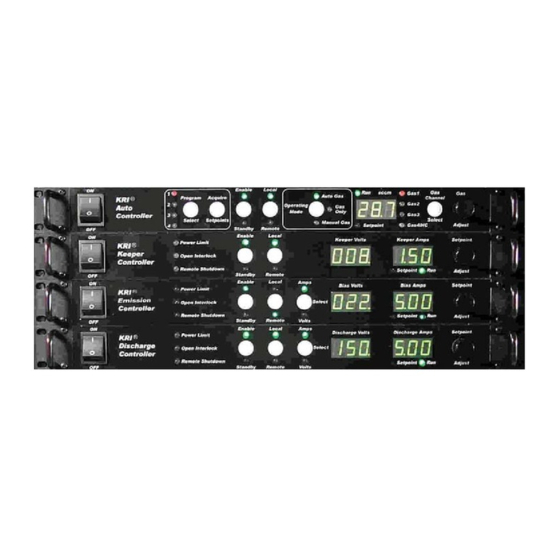
GENERAL DESCRIPTION AND SPECIFICATIONS GENERAL DESCRIPTION AND SPECIFICATIONS Fig. 2-1. Front view of controller for End Hall ion source. _______________________________________________________________________ Copyright © 2010 by Kaufman & Robinson, Inc., 1306 Blue Spruce Drive, Unit A, Fort Collins, CO 80524 Tel: 970-495-0187, Fax: 970-484-9350, Internet: www.ionsources.com... -
Page 11: Rear View Of Controller For End Hall Ion Source
GENERAL DESCRIPTION AND SPECIFICATIONS GENERAL DESCRIPTION AND SPECIFICATIONS Fig. 2-2. Rear view of controller for End Hall ion source. _______________________________________________________________________ Copyright © 2010 by Kaufman & Robinson, Inc., 1306 Blue Spruce Drive, Unit A, Fort Collins, CO 80524 Tel: 970-495-0187, Fax: 970-484-9350, Internet: www.ionsources.com... -
Page 12: Installation
INSTALLATION 3. INSTALLATION This section describes how to install the Kaufman & Robinson, Inc., KRI® Control- ler package for the hollow cathode version of the End Hall Ion Source. 3.1 Unpack Unpack the Controller package for the End Hall Ion Source. Prior to shipment, the Controller was tested with the ion source to insure quality and verify the standard range of operation. -
Page 13: Install In Rack Mount Cabinet
INSTALLATION 3.2 Install in Rack Mount Cabinet The Controller is designed to be mounted in a standard 19-inch (48 cm) rack mount cabinet. To assure that the power cable that came with each controller is connected to that controller, the power cables can be connected as each controller is installed in the cabinet. -
Page 14: Connections Between Controller Components
INSTALLATION 3.4 Connections Between Controller Components The connections between Controller components are shown in Fig. 3-2, which shows the rear panels of the Auto Controller, and the Keeper, Emission and Discharge power supplies. The individual connections required are given be- low: •... - Page 15 INSTALLATION • Insert the other end of the short BLACK wire into one of the (-) negative connectors located on the rear panel of the Discharge Power Supply and tighten the screw above the appropriate connector. • Attach the ring terminal end of the operating cable GREEN/YELLOW wire into the ground stud of the Discharge Power Supply.
- Page 16 INSTALLATION purifi er is used in the hollow cathode gas line, it should be located upstream from the mass fl ow controller. • There is a two pin interlock connector located on the back of the Auto Con- troller. The unit comes supplied with a jumper installed in the interlock con- nector.
-
Page 17: Connect Controller To Ion Source
INSTALLATION Description Number Not used. Chassis Ground. Not used. 3.5 Connect Controller to Ion Source If the Ion Source has not been installed in the vacuum chamber, do so now, using the Installation/Inspection description in the ion source manual. The ion source installation procedures cover installation of the ion source, vacuum cables, gas tubing inside the vacuum chamber, as well as electrical and gas feedthroughs in the wall of the vacuum chamber. - Page 18 INSTALLATION INSTALLATION Fig. 3-1. Front view of controller for End-Hall ion source. _______________________________________________________________________ Copyright © 2010 by Kaufman & Robinson, Inc., 1306 Blue Spruce Drive, Unit A, Fort Collins, CO 80524 Tel: 970-495-0187, Fax: 970-484-9350, Internet: www.ionsources.com...
- Page 19 INSTALLATION INSTALLATION Fig. 3-2. Rear view of controller for End-Hall ion source. _______________________________________________________________________ Copyright © 2010 by Kaufman & Robinson, Inc., 1306 Blue Spruce Drive, Unit A, Fort Collins, CO 80524 Tel: 970-495-0187, Fax: 970-484-9350, Internet: www.ionsources.com...
-
Page 20: Initial Operation
INITIAL OPERATION 4. INITIAL OPERATION This initial operation is done locally from the front panel and serves to both demon- strate and provide familiarization with operation. Make sure that the Auto controller is switched to local mode. The description in this section assumes that the installa- tion sequence described in Section 3 of this manual and Section 2 in the ion source manual has been carried out. -
Page 21: Program Select
INITIAL OPERATION 4.3.1.1 Program Select The Auto controller is shipped with four programs stored. Pressing and releasing the white Program Select button will increment to the next program as indicated by the numbered red LED’s on the left side of the Program Select button. -
Page 22: Keeper Current Setpoint
INITIAL OPERATION be cleared when the Auto controller is turned back on. A shut off signal for the hollow cathode gas is also available for remote shut off without turning off the Auto Controller. During startup of the hollow cathode, the automatic sequencing of the Auto Controller will raise the gas fl... -
Page 23: Discharge Parameters
INITIAL OPERATION The Emission voltage and current setpoints can be adjusted by turning the Setpoint Adjust knob on the front of the Emission Power Supply. The setpoint being adjusted by the knob is indicated by the green LED’s on the front panel labeled Amps and Volts. These LED’s are located above and below the white Select button on the front panel of the Emission Power Supply. -
Page 24: Standby
INITIAL OPERATION vacuum facility pump speed or other process that take place while the ion source is running. 4.3.1.7 Standby Press and release the white Enable/Standby button on the front panel of the Auto Controller. Notice that the yellow Standby LED under the button turns on and the green Enable LED above the button turns off. -
Page 25: Gas Only Mode
INITIAL OPERATION particular ion source. Note that the vacuum facility pump speed or other processes that take place while the ion source is running may limit the operating range of the ion source. A program can be saved when the Auto Controller is enabled or when it is in standby. -
Page 26: Constant Current Mode
INITIAL OPERATION Auto Controller will only function in the gas only mode, which must be se- lected to clear the HLP 7 message from the display. There will be no com- munication link if the power is switched off to any of the power supplies or if any RS-485 cable connection on the rear panel is not connected to Auto Controller or any of the power supplies. - Page 27 INITIAL OPERATION dicated in the Emission Amps display. Note that the Emission cur- rent in amps is usually set equal to or up to 10% greater than the discharge current. • Use the white Select button on the Discharge Power Supply to se- lect Volts.
-
Page 28: Constant Voltage Mode
INITIAL OPERATION er supplies into Standby in that order by pressing the white Enable/ Standby button on each. • Put the gas fl ow into Standby by pressing the white Enable/Standby button on the auto controller. 4.3.2.2 Constant Voltage Mode The operating condition selected for this demonstration is with a 2.5 A, 150 V discharge, which is Constant Voltage Mode operation. -
Page 29: Manual Gas Mode
4-10 INITIAL OPERATION • Use the white Select button on the Discharge Power Supply to se- lect Volts. Turn the knob on the Discharge Power Supply until the discharge voltage is set to 150 volts as indicated on the Discharge Volts display. - Page 30 INITIAL OPERATION 4-11 Manual Gas mode operates the same as the auto gas mode except that there is no feedback loop for the gas fl ows to maintain the anode param- eters. This being the case, the gas channels can all be independently ad- justed during operation, where this was not possible in the Auto Gas mode.
-
Page 31: General Operation
GENERAL OPERATION 5. GENERAL OPERATION The quickest way to start operation of the KRI Ion Source and its Controller is to follow the sequence described in Section 4, Initial Operation. This section gives a general overview of the ion source power supplies and their interconnection with the ion source. - Page 32 GENERAL OPERATION or plasma beam. _______________________________________________________________________ Copyright © 2010 by Kaufman & Robinson, Inc., 1306 Blue Spruce Drive, Unit A, Fort Collins, CO 80524 Tel: 970-495-0187, Fax: 970-484-9350, Internet: www.ionsources.com...
- Page 33 GENERAL OPERATION Fig. 5-1. Schematic block diagram of ion source and power supplies. _______________________________________________________________________ Copyright © 2010 by Kaufman & Robinson, Inc., 1306 Blue Spruce Drive, Unit A, Fort Collins, CO 80524 Tel: 970-495-0187, Fax: 970-484-9350, Internet: www.ionsources.com...
-
Page 34: Remote/Automated Control
REMOTE/AUTOMATED CONTROL 6. REMOTE/AUTOMATED CONTROL The Auto controller has a variety of remote control options available. These options include a female DB-25 interface, A female DB-37 analog/digital interface and a female DB-9 RS-232 serial interface. Note: The Auto Controller must be in Standby to switch between local and remote operating modes. -
Page 35: Connector
REMOTE/AUTOMATED CONTROL table 6-1 selects the programs. Once the program is selected, connecting remote enable pin 36 to common pin 7 or 8 on rear panel DB-37 connec- tor enables it. Removing the connection between pin 36 and pin 7 or 8 returns the Auto Controller to Standby. -
Page 36: Remote Analog Setpoint Option On The Db-37 Connector
REMOTE/AUTOMATED CONTROL ● Remote Gas Channel Setpoints using Auto Gas or Manual Gas Modes The remote gas setpoints are not available when using the auto or manual gas modes, instead the starting gas fl ows are established by program- ming them from the front panel for each program. The gas for channel 4 is reserved for the hollow cathode. -
Page 37: Analog Outputs For The Db-37 Connector
REMOTE/AUTOMATED CONTROL Table 6-2. Pin descriptions for the analog inputs on the DB-37 connector. Description Number Discharge Voltage Setpoint. 0-5 volts corresponds with 0 to the maximum output voltage for the Discharge Power Supply. Referenced to pin 7 or 8. Emission current set point. - Page 38 REMOTE/AUTOMATED CONTROL Table 6-3. Pin descriptions for analog outputs on the DB-37 connector. Description Number Emission Current Output. 0-5 volts corresponds with 0 to the maximum Bias current in amps for the Emission Power Supply being used. Refer- enced to pin 7 or 8. Emission Voltage Output.
-
Page 39: Run Fault And Beam Good On The Db-37 Connector
REMOTE/AUTOMATED CONTROL 6.2.5 Run Fault and Beam Good on the DB-37 Connector The Run Fault and Beam Good are available for additional monitoring of the operational state of the auto controller and associated power supplies. These pins are described below in table 6-4. A Run Fault occurs when the discharge fails to start or goes out in Auto Gas mode. - Page 40 REMOTE/AUTOMATED CONTROL brief; see the detailed descriptions above to understand the full functionality. Table 6-5. Pin descriptions for the female DB-37 connector on the Auto Con- troller. Description Number Emission Current Output. 0-5 volts corresponds with 0 to the maximum emission current in amps for the Emission Power Supply being used.
- Page 41 REMOTE/AUTOMATED CONTROL Description Number Gas Channel 4 shut off. Connecting this pin to common pin 7 or 8 will disable the gas fl ow to the MFC and deactivate the additional MFC relay for channel 4, regardless of the input fl ow setting. Program Select 0.
-
Page 42: Interlock
REMOTE/AUTOMATED CONTROL Description Number Channel 4 setpoint. 0-5 volts corresponds with 0 to the maximum out- put for the MFC connected to Channel 4. Referenced to pin 13. output for the MFC connected to Channel 4. Referenced to pin 13. Gas Channel 1 shut off. -
Page 43: Remote Control Using The Rs-232 Serial Interface
6-10 REMOTE/AUTOMATED CONTROL Table 6-6. Interlock connections for the Auto Controller. Description Number Interlock Return – Common to chassis Active Low Interlock – Connect to common (Interlock pin 2, or DB-37 pin 7 or 8) to enable. 6.4 Remote Control using the RS-232 Serial Interface The RS-232 serial interface provides full remote control of the Auto Controller. -
Page 44: Vrb - Verbose Command
REMOTE/AUTOMATED CONTROL 6-11 The following convections are used for the command and query descrip- tions in the following subsections: “ “ – Text or numerical values inside double quotation marks indicate the exact response from the Auto Controller. The quotation marks are not in- cluded in the actual response. -
Page 45: Com - Enable Rs-232 Command Or Status Query
6-12 REMOTE/AUTOMATED CONTROL valid command or query is “OK” followed by CR/LF and the “>” symbol as the next line prompt for the following command/query. The response to a query will also include the requested information with descriptive test. Invalid commands generate an “Invalid Command” response followed by CR/LF and the “>”... -
Page 46: Idn? - Unit Identifi Cation Query
REMOTE/AUTOMATED CONTROL 6-13 COM:1 – Place unit in ‘RS-232 Remote’ control. If the unit is not in front panel remote and standby, the unit issues the following response: “Unit must be in STANDBY AND front panel REMOTE”. COM:0 – Disable ‘RS232 remote’ control. If the unit is not in ‘Standby’... -
Page 47: Rst - Reset Command
6-14 REMOTE/AUTOMATED CONTROL fi rmware version number is month/day/year (MMDDYY). Example: *IDN?<cr><lf> Example response: “KRI,AC1,102862,052690,111506” 6.4.4.4 *RST – Reset Command The RST command will return to the unit to ‘Standby’ and clear any ‘recoverable’ error message(s). The unit will also be set to ‘Terse’ mode Command: *RST Example: *RST<cr><lf>... -
Page 48: Out - System Level Output Control Command
REMOTE/AUTOMATED CONTROL 6-15 12 = HLP 12 – Gas fault. 13 = HLP 13 – Internal communication error. Example Response: “10” 6.4.4.6 OUT - System Level Output Control Command or Status Query The OUT command ‘Enables’, ‘Disables’, or queries the output state of the system depending on the parameter following it. -
Page 49: Beam - Beam Good Query
6-16 REMOTE/AUTOMATED CONTROL Parameter/Response: 0 = Auto Gas. 1 = Manual Gas. 2 = Gas Only. Example: MDE:0<cr><lf> - Put unit in ‘Auto Gas’ If COM is active and unit is ‘Enabled’, the response of the unit is: “Unit must be in STANDBY”. If the COM is not ‘Enabled’, the command is ignored both in ‘Terse’... -
Page 50: P - Program Value Read/Write Command
REMOTE/AUTOMATED CONTROL 6-17 6.4.4.9 P - Program Value Read/Write Command The P command selects or queries the active program, or sets or queries the active operating values for a program depending on the parameters included with the command. The operating values are the gas fl ows for the MFC’s, and the currents and voltages for the power supplies. - Page 51 6-18 REMOTE/AUTOMATED CONTROL There are 9 <parameters> for setting an individual (value). Each of these <parmeters>, which are three letters long, are listed below along with the description and the number of signifi cant digits and decimal places shown as x: GS1 –...
- Page 52 REMOTE/AUTOMATED CONTROL 6-19 shown with their mnemonic equivalents listed above. In real use, these abbreviations would be actual numerical values. These nu- merical values must be valid for the confi guration being programmed remotely since the Auto-Controller does not know the maximum ranges of the units attached.
- Page 53 6-20 REMOTE/AUTOMATED CONTROL Gas Channel 4 = 10.000 Discharge Volts = .200.000 Discharge Amps = 3.000 Emission/Bias Amps = 3.000 Bias Volts = 120.000 Keeper Amps = 1.500”. The command can also be used to set or get a single value for a program.
-
Page 54: Feedback Values
REMOTE/AUTOMATED CONTROL 6-21 those (values) to the maximum value. However, this is not true for the gas channel values. If a gas channel (value) is larger than the defi ned maximum, the auto controller will respond with: “Target value greater than defi ned max”. If a gas channel maximum is set to 0 or off, then sending a (value) to that gas channel will generate the following response: “Gas Channel x disabled”... -
Page 55: Cfg? - Query Current System Confi Guration
6-22 REMOTE/AUTOMATED CONTROL Keeper Amps = 1.500 Bias Volts = 38.000 Bias Amps = 3.000” In ‘Terse’ mode the response will be a comma delimited string of values only in the same as order shown above for the ‘Verbose’ mode. 6.4.4.11 CFG? –... - Page 56 REMOTE/AUTOMATED CONTROL 6-23 Example: LRN:0<cr><lf> Example: LRN:1<cr><lf> Example: LRN?<cr><lf> In VERBOSE, the response is “On”, or “Off”. In TERSE, the response is “1”, or “0”, respectively. _______________________________________________________________________ Copyright © 2010 by Kaufman & Robinson, Inc., 1306 Blue Spruce Drive, Unit A, Fort Collins, CO 80524 Tel: 970-495-0187, Fax: 970-484-9350, Internet: www.ionsources.com...
-
Page 57: Diagnostics
DIAGNOSTICS 7. Diagnostics The following information is intended to facilitate troubleshooting of the Auto Con- troller and associated power supplies. This information assumes that the Auto Controller and power supplies are connected to power and that all interconnects between power supplies and the ion source cable are made correctly. It is also assumed that all gas connections are in good condition and that the gas circuit is complete from the gas bottle to the ion source. - Page 58 DIAGNOSTICS Help Code Possible Causes or Error Description Message Corrective Action current fl owing in the recovers from error condition if ground connection of the problem goes away. serial interface between the unit and the Computer. Make sure all of the equipment Shows up only in remote has adequate grounding.
- Page 59 DIAGNOSTICS Help Code Possible Causes or Error Description Message Corrective Action Press and release the STANDBY/ ENABLE button or remove the remote enable signal to clear the code. The unit remains in STANDBY until STANDBY/EN- ABLE is pressed again or the remote enable signal is reapplied.
-
Page 60: Keeper Power Supply
DIAGNOSTICS Help Code Possible Causes or Error Description Message Corrective Action HLP 13 Master Communication Switch off the power until the dis- Error. play is dark and then switch the power back on to reset. Press and release the STANDBY/ ENABLE button or remove the remote enable signal to clear the code. -
Page 61: Help Codes And Error Messages For The Keeper Power Supply
DIAGNOSTICS action that may need to be taken. Table 7-2. Help codes and error messages for the Keeper Power Supply. Help Code Possible Causes or Error Description and Corrective Message Action Current Latch – A high Switch off the power until the HLP 1 current was encountered. -
Page 62: Emission And Discharge Power Supplies
DIAGNOSTICS Help Code Description Possible Causes or Error and Corrective Message Action Open or shorted cathode or keep- er cables. Inspect the in vacuum cable and replace if necessary. No gas fl ow to the hollow cathode. Due to empty gas bottle, valve off somewhere in the gas supply, faulty MFC, or MFC cable dam- aged or unplugged. - Page 63 DIAGNOSTICS Help Code Description Possible Causes or Error and Corrective Message Action HLP 1 Current Latch – A high current was encountered. Switch off the power until the Power supply latched off to display is dark and then switch the prevent a failure.
-
Page 64: Appendix
APPENDIX 8. APPENDIX The auto controller is preset to match the product supplied with it so the user should usually not need to enter the setup mode. The setup is provided in case there has been a change to the original product. 8.1 Auto Controller Setup 1. - Page 65 APPENDIX 6. The display should now be alternately fl ashing CP4 and 10. This is the cath- ode purge value. The number 10 is the fl ow in sccm that fl ows even when the Auto Controller is in standby if either the Auto Gas or Manual Gas Op- erating Mode are selected.
-
Page 66: Limited Warranty
LIMITED WARRANTY 9. LIMITED WARRANTY Kaufman & Robinson, Inc. (KRI) warrants to the purchaser or end user of the equip- ment it sells that such equipment will be free from defects in material and workman- ship under normal use and service. This warranty is for a period of two years from the date of original shipment F.O.B KRI’s facility, Fort Collins, Colorado. -
Page 67: Service And Technical Information
SERVICE AND TECHNICAL INFORMATION 10-1 10. SERVICE AND TECHNICAL INFORMATION For technical information, repairs or replacement during Warranty, or repairs there- after, please contact: Kaufman & Robinson, Inc. 1306 Blue Spruce Dr. Unit A Fort Collins, CO 80524 Tel.: 970-495-0187 Fax.: 970-484-9350 www.ionsources.com Please include the following details relating to the problem encountered or the...
Need help?
Do you have a question about the eHC 3005A and is the answer not in the manual?
Questions and answers