Table of Contents
Advertisement
Quick Links
6 Kripes Road - PO Box 260 - East Granby, CT 06026 USA
Fax: (860) 653-0486
E-Mail: info@magnatech-lp.com
Phone: (860) 653-2573
Web:
www.magnatech-lp.com
Operating and Maintenance
Instruction Manual
For
Pipeliner II Model 609A
Orbital Weld Head
- Wire Feed on Floor (WFOF) version
- Wire Feed on Hand (WFOH version
- Wire Feed Push-pull (WFPP) version
For Use With
MPS 4000 Power Source & Model 712 Controller
(See Separate Manual)
Rev 01-14-2009
Advertisement
Table of Contents

Related Manuals for MAGNATECH Pipeliner II 609A


Summary of Contents for MAGNATECH Pipeliner II 609A
- Page 1 6 Kripes Road - PO Box 260 - East Granby, CT 06026 USA Fax: (860) 653-0486 E-Mail: info@magnatech-lp.com Phone: (860) 653-2573 Web: www.magnatech-lp.com Operating and Maintenance Instruction Manual Pipeliner II Model 609A Orbital Weld Head - Wire Feed on Floor (WFOF) version...
- Page 2 TABLE OF CONTENTS SECTION TITLE PAGE INTRODUCTION Copyright Notice PIPELINER IIC COMPONENT INVENTORY Weld Head 609A Guide Rings Optional Installed Components/Kits Optional Free-Standing (Unattached) Components SAFETY INSTRUCTION AND WARNING FOR OPERATION AND ARC WELDING EQUIPMENT Important to Read Introduction Shock Prevention Burn Prevention Toxic Fume Prevention Compressed Gas Cylinder Handling...
-
Page 3: Table Of Contents
TABLE OF CONTENTS - CONTINUED SECTION TITLE PAGE USE OF WELD HEAD ON PREHEATED PIPE 10.0 ADAPTOR FEET KITS FOR PIPELINER GUIDE RING TO ALLOW USE ON SMALLER PIPE SIZES 11.0 TORCH EXPENDABLE COMPONENTS LIST 11.1 For "Binzel" Torch P/N 103364-6 12.0 SUMMARY OF CAUTIONS 12.1... - Page 4 ATTENTION:ALL FASTENERS ON THESE WELD HEAD MODELS ARE METRIC COPYRIGHT NOTICE This manual and the information contained herein is the property of Magnatech Limited Partnership. It is proprietary and shall not be copied in whole or in part without the prior express written permission of Magnatech Limited Partnership.
- Page 5 PIPELINER IIC COMPONENT INVENTORY Each model comes equipped with the following components: WELD HEAD 609A S/N _________________________ 1Pipeliner II Weld Head Model 609A (WFOF)609AF0AWC0 Floor-mounted Feeder with Pneumatic Mounting and Pendular Oscillation Option 1 - Weld Head - 103951-PD 1 - Torch Cable - 103090-15-PD 1 - Accessories Kit - 104017-1 1 - Dual Regulator - 38416 1 - Operation Manual - Manual...
- Page 6 1Pipeliner II Weld Head Model 609A, 609AGEBWC9 Pneumatic Mounting, 2-Roll Head- Mounted Feeder (WFOH), 25' (8m) Torch Cable 1 - Weld Head - 103951-PD 1 - Torch Cable - 103364-25-P 1 - Wire Drive Kit - 104022-1 1 - Accessories Kit - 104017-1 1 - Dual Regulator - 38416 1 - Operation Manual - Manual 1Pipeliner II Weld Head Model 609A, 609AGEC0C9...
- Page 7 AND/OR BEEN MADE AWARE OF ALL OF THE SAFETY RELATED ITEMS CONTAINED IN THIS MANUAL. READ AND UNDERSTAND THESE INSTRUCTIONS BEFORE INSTALLING, OPERATING OR SERVICING MAGNATECH EQUIPMENT OR AUXILIARY EQUIPMENT SUPPLIED AS PART OF THE WELDING SYSTEM. INTRODUCTION Welding products and welding processes can cause serious injury or death, and possible damage to other equipment if the operator does not strictly observe all safety rules and take precautionary actions.
- Page 8 currents to flow through the body. Do not work in damp area without being extremely careful. Stand on dry rubber mats or dry wood and use insulating gloves when dampness or sweat cannot be avoided. Keep clothing dry. 3.3.1 Installation and Grounding of Electrically Powered Equipment Electrical equipment must be installed and maintained in accordance with the National Electrical Code, NFPA 70, and local codes.
- Page 9 3.4.1 Protective Clothing Wear gloves, suitable long sleeved shirts/jackets, safety shoes, welding helmet, and other articles needed to shield the skin and to prevent injury from arc burns. Wear ear plugs if welding overhead or in a confined space. Wear a hard hat if others are working above you. 3.4.2 Eye and Head Protection Protect your eyes and head by wearing a welding helmet fitted with a...
- Page 10 3.5.4 Welding Area Do not weld in locations close to chlorinated vapors coming from degreasing, cleaning or spraying operations. The heat and rays from the arc react with the vapors to form highly toxic PHOSGENE. Work in a confined space only if it is being adequately ventilated, and if ventilation is not adequate, wear an air-supplied respirator (see ANSI 2.37).
- Page 11 Government Printing Office, Washington, DC 20402. 3.8.6 NFPA Standard 51B. CUTTING AND WELDING PROCESSES. Order from the National Fire Protection Association, Batterymarch Park, Quincy, MA 02269. 3.8.7 CGA Pamphlet P-1, SAFE HANDLING OF COMPRESSED GASES IN CYLINDERS. Order from the Compressed Gas Association 1235 Jeff Davis Highway, Arlington, VA 22202.
- Page 14 WARRANTY POLICY & SUPPORT General: Magnatech warrants equipment that it manufactures to be free from defects from material and workmanship under normal use and service for the periods defined below. This Warranty shall apply to the Original Purchaser only, and is not transferable.
- Page 15 Magnatech shall not be held liable for any lost profit or other damage, delay or loss which may result directly or indirectly from the adjustment, alteration, repair, maintenance, operation, or interruption thereof, of any said equipment.
- Page 16 MAGNATECH PRODUCT WARRANTY REGISTRATION Please provide the following information and mail/fax to Magnatech. This will allow us to insure correct replacement parts are supplied, service bulletins reach the correct person, and provide a contact person for service. Product Name:...
- Page 17 Magnatech Ltd. Partnership Affix P. O. Box 260 Postage East Granby, CT 06026 Magnatech Limited Partnership Attn: Sales Dept. P. O. Box 260 East Granby, CT 06026...
- Page 18 Support: Now that you have purchased a Magnatech product, we want to confirm that we intend to support you after the sale with the expedient service and technical support which we strive to maintain at world-class standards. A. Sales U.S. Headquarters:...
- Page 19 SPECIFICATIONS: SPECIFICATIONS PIPELINER WELD HEAD APPLICATIONS 6" pipe (168mm) and larger Pipe Size: For 6" pipe (168mm) and larger Guide Rings: Wall Thickness: Unlimited Wall Thickness: All materials which can be welded with GMAW or Pipe Material: FCAW process. Flx-Tracks available. Linear and Large Diameter Applications: FILLER WIRE MODULE...
- Page 20 0-76cm/minute (0-30 IPM) TORCH PROPULSION MODULE Clutch allows rapid repositioning of weld Head. 300 amps at 100% duty cycle. WATER-COOLED TORCH WFOF -4.6M (15’) TORCH CABLE LENGTH WFOH-1.5M (50’) WFPP-8m (25’) Extension cables available. WELD HEAD DIMENSIONS/WEIGHT Minimum Axial Radial Overall Length Clearance...
- Page 21 INSTALLATION (Refer to Hook-Up Schematic in Section 17) Installation of the welding system consists of locating and interconnecting the various system components such as the welding power supply, water circulator, controller, shield gas, work cable, weld Head and extension cables (if any). Locate the welding power supply in the work area.
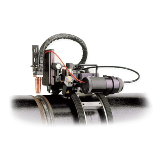
- Page 22 FUNCTIONAL DESCRIPTION - WELD HEAD N : ALL FASTENERS USED ON THIS WELD HEAD ARE METRIC. ALL MOTORS AND OTHER ELECTRICAL COMPONENTS ON THE HEAD ARE OPERATED WITH 42V DC CURRENT OR LESS, PREVENTING ANY SHOCK HAZARD. The Pipeliner Weld Head consists of the following subsystems: Oscillator Torch Arc Gap Control Mechanism Tractor...
- Page 23 The TRAVEL DIRECTION SWITCH determines the direction of rotation of the weld Head when welding is initiated. It should be noted that there is no conventional "forward" direction for the Pipeliner. This switch allows bi- directional welding - for example the use of double down or double up welding techniques where travel direction is changed twice per pass.
- Page 24 SET-UP AND OPERATION MOUNTING THE FRICTION DRIVE GUIDE RING (P/N 103040-XXXXX) 8.1.1 Adjust the tensioning screw on the "hinge side" of the guide ring so there is approximately ½" (13mm) space between the tab and the slot of each rail. 8.1.2 Open the guide ring and place it over the top of the pipe with the tensioning screw heads facing you.
- Page 25 8.2.2 Using the Pneumatic Push Button Release Option The four thumb screws can be replaced with four miniature pneumatic cylinders (factory installation only). A push-button valve mounted on the Head pressurizes all four cylinders which cause all four rollers to simultaneously move downward and outward, allowing the Head to be installed or removed.
- Page 26 8.5.1.4 Check primary input power at customer facility. 8.5.1.5 Be sure power supply is switched for proper voltage before connecting. 8.5.1.6 Remove cooler and check or fill with Magnatech-approved coolant. If extension cables supplied, explain possible need for two-step filling operation.
- Page 28 8.5.1.7 Hook up weld Head to Controller. All connections are specific. Emphasize do not force connection, and if difficult, probably incorrect. 8.5.1.8 Gas In from gas supply, Gas Out to Weld Head. 8.5.1.9 Ensure water lines are correctly mated by color. 8.5.1.10 View fuses and connections.
- Page 29 Demonstrate torch angles, i.e., lag, lead, in (towards weld Head), out, etc. Explain usage advantages and possible problems. Demonstrate weld Head installation on the guide ring at different positions. Demonstrate use of clutch for rapid positioning of weld Head. 8.5.2.7 Pendant. Show and explain Pendant Control layout.
- Page 30 Demonstrate proper grinding technique and transition of start/stops. Demonstrate different torch positions and possible usage. Demonstrate the adjustment of pre-purge gas time and proper gas flow range. Stress importance of contact tip wear on welding performance. Discuss contact tip location (flush/recessed) for different welding modes.
-
Page 31: Use Of Weld Head On Preheated Pipe
USE OF WELD HEAD ON PREHEATED PIPE. If the Pipeliner Head and Guide Ring are to be used on preheated pipe, precautions may be required to prevent damage for preheats of 95º C (200ºF) or lower, no special action is required. For preheat higher (especially if preheat temp is to be over 150ºC (300ºF) it is necessary to use an oversize Guide Ring and spacers (adaptors) to create additional air spaces between the Guide Ring/weld Head and hot pipe surface. -
Page 32: Adaptor Feet Kits For Pipeliner Guide Ring To Allow
To allow use of a standard guide ring on a special non-standard size of pipe. While Magnatech has the capability of engineering a guide ring for any size, we would charge additional for that service. In most cases, the additional radial clearance is not significant and the customer could use the next size larger standard pipe guide ring with adaptors. - Page 33 The case where the customer wants to weld a pipe that is exactly 4” (or two times 50mm) smaller in size and will use the rectangular tube. The case with either the square or rectangular tube where the flat metal shim is required because of an intermediate size.
-
Page 35: Torch Expendable Components List
11.0 TORCH EXPENDABLE COMPONENT LISTS 11.1 FOR "BINZEL" TORCH P/N 103364-L (STANDARD COMPONENTS USED ON BINZEL MB-602-D TORCH) MAGNATECH BINZEL DESCRIPTION 8891 039.0008 GAS DIFFUSER 8894 145.013 NOZZLE, SMALL CONICAL - (0.61"/15/5MM DIA.) 8890 145.0088 NOZZLE, CONICAL (0.71"/18MM) 8893 145.0052 NOZZLE, CYLINDRICAL (0.87"/22MM) -
Page 36: Summary Of Cautions
12.0 SUMMARY OF CAUTIONS 12.1 SHOCK PREVENTION Always disconnect the AC power plug before removing the panels of the Controller to avoid electrical shock and the possibility of shorting or grounding the electrical circuitry. Always disconnect primary power to the power source before removing panels. Do not remove panels from the power source until the maintenance manual has been read and fully understood, as there may be lethal voltage present even after the primary power is disconnected. -
Page 37: Always Stop Motors Before Reversing
damage the oscillator mechanism. Raise the torch out of the groove before actuating the centering control. 12.6 ALWAYS STOP MOTORS BEFORE REVERSING Do not snap reverse motors. Switch motor to the "OFF" position before reversing direction. Fast reversing can reduce motor power and shorten life. 12.7 ABRASIVE GRINDING DUST WILL CAUSE PREMATURE WEAR Avoid grinding in the vicinity of the weld Head and Pendant. -
Page 38: Weld Process Development
13.0 WELD PROCESS DEVELOPMENT It is not possible within the context of this operation manual to provide a comprehensive guide to weld procedure development. Weld procedure development requires the experience of a competent individual experienced in the GMAW or FCAW process. It is also important to note at this point that the Pipeliner should more properly be termed a Mechanized Pipe Welding System. - Page 39 Irregular wire feed, burnback. 1. Check drive roll pressure. 2. Check, adjust wire feed speed. 3. Clean or replace contact tip. 4. Check input line voltage for fluctuations. 5. Remove kinked electrode wire; replace wire spool. 6. Lubricate or replace conduit liner. Overheating welding cables.
- Page 40 Undercutting. 1. Reduce power. 2. Reduce welding speed. 3. Shorten arc length.
- Page 41 Cracked welds. 1. Check design of root opening, root face dimensions, angle. 2. Check electrode wire compatibility with base metal. 3. Change welding speed or shielding gas to obtain a more convex bead. 4. Change torch angle to improve deposition. 5.
- Page 42 With a shorter than recommended electrode extension, the energy to the weld puddle is reduced, resulting in gas moisture which would normally escape before the puddle solidifies being trapped in the freezing puddle. This may appear as scattered pores, or as long connected pores or tracks immediately underneath the slag.
- Page 43 Remote Pendant...
- Page 44 PIPELINER WELD LOG SHEET INDIVIDUAL PASS DATA PIPE SIZE:_____________________________ WALL:_________________________________ TRAVEL DELAY:_______________________ ACTUAL WIRE SPEED: PRIMARY:_______________________ DWELL:_________________________ ARC TRIM DIAL SETTING:____________________________________________________________ ACTUAL VOLTS:_______________________ ON / OFF PULSE FREQUENCY:____________________ TRAVEL SPEED DIAL SETTING:_______________________________________________________ ACTUAL TRAVEL SPEED AT PIPE:____________________________________________________* *(GUIDE RING DIA./PIPE DIA. X DIAL SETTING IN IPM) ON / OFF ON / OFF ON / OFF...
- Page 45 PIPELINER WELD LOG SHEET DATE:____________________ Pipe Size:___________” O.D. (__________mm) x ________” (_______mm) Wall Thickness Pipe Material:________________________________________________________________________ PQR No.:________________________________ Company Developed For:______________________________________________________________ Program Developed By:_______________________________________________________________ Weld Position:____________ Weld Progression (Double-Up or Double-Down):____________ Joint Geometry:______________________________________________________________________ Filler Material:_________________________________________ Wire Diameter:_______________ System Model/Power Source Used:____________________________________________________ Gas Nozzle Orifice:___________________________________________________________________ Contact Tip Size: Flush/Extended______________________________________________________ Contact Tip Size: Std./Tapered________________________________________________________...
-
Page 46: Electrode Extension Often Neglected When Using Self-Shielded Cored Wires
14.0 ELECTRODE EXTENSION OFTEN NEGLECTED WHEN USING SELF-SHIELDED CORED WIRES... -
Page 49: Preventing The Effects Of Moisture Contamination Of Flux Core Wire
15.0 PREVENTING THE EFFECTS OF MOISTURE CONTAMINATION OF FLUX CORE WIRE...
Need help?
Do you have a question about the Pipeliner II 609A and is the answer not in the manual?
Questions and answers