
Related Manuals for hydrotab FW Series

Summary of Contents for hydrotab FW Series
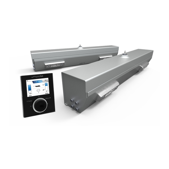
- Page 1 Hydro Hydro Marine Engineering Marine Engineering OPERATOR'S MANUAL NMEA 2000 NMEA 0183 Hydrotab FW Series installation & Moby Automatic controller Hydrotab BT Series...
-
Page 2: Disclaimer
Trademark Notice Fair use statement Hydrotab is a registered trademark of Olympic This manual can be printed or copied for your Engineering Ltd, Greece. All other trademarks, own use only. Copies should not be provided... -
Page 3: Table Of Contents
Required Tools for Installation Before Installation Safety precautions F-type Installation V-type Installation FW Series Interceptor and Anode Mounting and Coating Instructions Air Unit Installation Moby Controller Installation Air Unit: Direct Installation Diagram Air Unit: Installation Diagram on existing NMEA network... -
Page 4: Installation Kit
Marine Engineering Installation Kit 1. Two interceptors 2. Two drilling patterns Χρησιμοποιείστε τρυπάνι Ø5,5mm x 12 τρύπες Χρησιμοποιείστε τρυπάνι Ø5,5mm x 12 τρύπες 3. One Hydrotab AIR unit 24VDC 4. Cables Inline terminator 3m-supply cable - Female 10m Female-Female 3m Male-Female 5. -
Page 5: Required Tools For Installation
Hydro Marine Engineering Required Tools for Installation Marking tool Drill Ø5.5 (pencil or marker) Drill Ø3 Drill Ø4 Drill Ø8,5 Hole Saw Ø70 Screwdriver Allen Key No 5 Drilling tool Sikaflex gun Before installation: Make sure there are no obstructions in the interior of the If there is a double installation on the boat please allow a 18 to 20 mm area to be drilled (tanks, fuel lines, cabling) which can be space between them (Figure 2). -
Page 6: F-Type Installation
Hydro F type installation Marine Engineering Place the bottom line of the drilling template in the Attention! same plane with the hull bottom plane without any After the opening of the holes, use sealant sikaflex 291 part protruding (Figure 6) (Figure 8) in order to: - seal the holes - compensate for transom plane irregularities... - Page 7 Hydro Marine Engineering Place the F fitting close to the transom, apply the necessary In order to install the F fitting, create a 9mm amount of sealant (sikaflex) and mount. (Figure 13) diameter hole. (Figure 10) Tight the screws and connect the fitting with the interceptor using an appropriate length of pipe.
-
Page 8: V-Type Installation
Hydro Marine Engineering V type installation Place the bottom line of the drilling template in Use sikaflex No 291 in order to seal the rubber same plane with the hull bottom plane without any fitting (Figure 19). part protruding ( Figure 16 ) After placing the template in the desired position mark the pilot holes with a marking tool. - Page 9 Hydro Marine Engineering Attention: Remove the cover of the unit and fix it with the screws on the After the opening of the holes use sealant sikaflex 291 transom using the holes previously opened (Figure 21) (Figure 20) in order to: - seal the holes - compensate for transom plane irregularities - cement the unit to the hull...
-
Page 10: Fw Series Interceptor And Anode Mounting And Coating Instructions
Hydro Marine Engineering FW Series Interceptor and Anode Mounting and Coating Instructions Note 1: You may apply protection coating on interceptor if you'd like so, but: 1. Do not apply coating on anodes 2. Do not apply coating on the area of interceptors which is in contact with anode (see Fig. 1a, 1b, 1c). -
Page 11: Air Unit Installation
Hydro Marine Engineering Air Unit Max Installation WARNING: THE AIR UNIT MUST BE INSTALLED IN A COMPARTMENT FREE OF EXPLOSIVE OR FLAMMABLE GASES WARNING: PLEASE INSURE THAT THE AIR UNIT IS INSTALLED ACCORDING TO THE IP30 LIMITATIONS. IP30 : Protected from tools and wires greater than 2.5 millimeters. Not protected from liquids. WARNING: DO NOT MOUNT the Air Unit upside-down... - Page 12 Hydro Marine Engineering Pneumatic Connection Connect the push-in fitting Cut the 8mm pipe at the proper length and connect it to the Air Unit Technical Data & Dimensions Air Unit Max DataSheet Compressor power 380 W Air compressor type Brushless, oil-free Voltage 24 V Amps...
-
Page 13: Moby Controller Installation
Hydro Marine Engineering Moby Controller Installation Tape 1. Place the Moby Drilling Pattern in the desired position (preferably a clean and easy-to-access area near the steering wheel of the boat, and with max. inclination angle at 80°). 3. Drill the 4 holes according to the provided 4. -
Page 14: Air Unit: Direct Installation Diagram
Hydro Marine Engineering Direct Installation Diagram Moby Controller Air Unit Max Flybridge OPTIONAL controller USE INLINE TERMINATOR CABLE 3m - MF TO 30A FUSE CABLE CABLE 10m - MF 10m - FF In case a new NMEA 2000 instrument to be added, a proper NMEA Network must be built. Installation diagram on existing NMEA Network Flybridge Air Unit Max... -
Page 15: Double Speed Air Unit: Direct Installation Diagram
Air Unit Max Electrical Diagram Air Unit Max Pneumatic Diagram Compressor NM E A 2000 500.AIR-N2Κ-ΤΗ-V2.1 VALVE GROUP CAN-H CAN-L -12/24V RM+12V -12/24V +12/24V F1 F1 Switch + - +12V Battery Compressor Timer (PNE-01242A) IMPORTANT: THE SWITCHES MUST BE STRICTLY SET AS SHOWN (DIP1, DIP2, DIP3, DIP4 RIGHT) SYMBOL Part No... -
Page 16: Single Air Unit Electrical Diagram
Hydro Marine Engineering Spare Parts & order information CODE ID No. DESCRIPTION 640FW 700FW 800FW 1000FW ASM-00719 ASM-00401 ASM-00158 ASM-00160 Body ASM-00815 ASM-00430 ASM-00087 ASM-00092 Inflatable tubular (F) ASM-00292 ASM-00431 ASM-00293 ASM-00294 Inflatable tubular (V) GEN-00025 Plastic guides GEN-00032 Spring support LAS-00598 LAS-00459 LAS-00127... -
Page 17: Double Speed Air Unit Electrical Diagram
Hydro Marine Engineering Spare Parts - Air Unit Max Valves Assembly (see below) BOM ID PartNo Description QTY. BOM ID PartNo Description QTY. ELE-00535 5PIN PCB MALE CONNECTOR PNE-01242A COMPRESSOR ELE-00647 MINI USB PORT, FEMALE PNE-01242B TRASNFORMER ELE-00698 RELAY TIMER PNE-01242C FILTER GEN-00405 COVER... -
Page 18: Spare Parts List And Order Information
Hydro Marine Engineering Moby Troubleshooting Moby controller is Moby controller is on but flaps do not on but flaps do not operate on manual operate on manual Go to System Information. Do you notice N2K error and Temperature Offline? 1) Is there power supply 1) Open the air unit. -
Page 19: Spare Parts List - Single Air Unit (Asm-01065)
Hydrotab's warranty only covers the repair or replacement of spare parts. System selections It is the sole responsibility of the buyer to choose the correct system and even with Hydrotab’s suggestion for a system, the overall responsibility is with the buyer. -
Page 20: Spare Parts List - Double Speed Air Unit (Asm-01174)
Hydro Marine Engineering 4, Papazoglou str. Hydro GR-17778 Athens Greece email: info@hydrotab.gr website: www.hydrotab.gr Marine Engineering REV.B...
Need help?
Do you have a question about the FW Series and is the answer not in the manual?
Questions and answers