
Related Manuals for Oden Control P30


Summary of Contents for Oden Control P30
- Page 1 Oden Control User’s gUide installation and maintenance manUal oden p30 www.odencontrol.se...
-
Page 2: Table Of Contents
CONTENT Content ................................1 General information............................2 Technical description............................4 Mechanical installation............................7 Electric connection ............................10 The calibration system.............................11 OVP – Oden Valve Program ...........................13 Maintenance ..............................15 Trouble shooting..............................16 Tips..................................17 Appendix: Technical specifications Drawings Electrical connection Version 2009-04-17 www.odencontrol.se... -
Page 3: General Information
GENERAL INFORMATION 2.1. The Oden family of electric actuators The Oden family of electric actuators are made specifically for the process industry. The family consists of turning and linear actuators designed for the most demanding industry environments. The standard product line of electric actuators consists of five basic units in different sizes. - Page 4 2.3. Terms concerning safety It is of outmost importance that all users follow these instructions on how to install, maintain and use this series of electric actuators. The safety terms DANGER, WARNING, CAUTION and NOTE are used in these instructions to point out particular dangers and/or providing additional information on aspects which are not readily apparent.
-
Page 5: Technical Description
TECHNICAL DESCRIPTION 3.1. General The Oden P30-module system consists of: − P30BU Basic Unit − 30R Turning module − 30L Linear module − Adapter kit for turning actuator − Adapter kit for linear actuator Product Type of Basic Unit Module... - Page 6 30R3 is a turning unit normally used for a 90 valve movement and has a tapered clamping sleeve (conical coupling) for easy fitting to the valve spindle. This unit has an internal mechanical stop. 3.4. Adapter kit for turning actuator The turning adapter kit consists of: −...
- Page 7 3.7. Cable with connector The standard 10 m shielded cable has 9 active coloured wires and a cable connector. The cable is designed for fixed installation and if placed in extreme outdoor environment, it should be covered with a protective hose. 3.8.
-
Page 8: Mechanical Installation
The cable must be clamped (fixed installation) between the actuator and the connection board. 4.1. Confirmation of delivered items Please check that the delivery is complete according to the delivery specification: − P30 Basic Unit − 10 m cable with connector − Analogue connection board −... - Page 9 3. Press the turning module 30R1 in place until it is resting at the surface of the valve flange adapter. Tighten the clamp collar screws. Check that you can move the valve by hand. Put the valve spindle to closed position. NB Some valve spindles are changing their axial position in closed position.
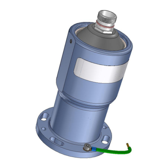
- Page 10 8. Attach P30BU to 30R3 using four M8x25 with washers and Loctite 243. 9. The ground wire (green/yellow) which is fitted to the actuators flange should be connected to a suitable ground point at the valve. 10. All threads should be locked by Loctite 243. 11.
-
Page 11: Electric Connection
Cable connection P30 is delivered with a standard cable of 10m and the Connection board A. Connect the free end of the cable with the connection board using the colour codes. Note that the cable shield should be grounded at the free end of the cable. -
Page 12: The Calibration System
THE CALIBRATION SYSTEM To calibrate the actuator/valve-system means to identify the closed valve position which corresponds to the closed position of the control signal, normally 4 mA. There are two types of calibration methods; Power Calibration (mostly used) and Position Calibration. Which one to use depends on type of application. 6.1. - Page 13 Remove any connections to the terminal block inlet number 3 and 5 (+IN and +OUT) at the connection board. Short-circuit terminal number 3 and 5 (+IN and +OUT). Connect the power, 24 VDC. The actuator will now remember this position as the calibration position and will start opening the valve.
-
Page 14: Ovp - Oden Valve Program
OVP versions − P30 with serial number 09xxxx and higher: Use OVP version 4.1 − P30 with serial number 96xxxx – 99xxxx and 00xxxx to 08xxxx: Use OVP version 3.8 7.2. To start using OVP To start using the OVP software: −... - Page 15 7.6. Parameters in OVP Parameter Description Default value Default value P30 Turning P30 Linear Closing direction Sets closing direction. Viewed from the Clockwise actuator towards the valve Valve pitch Sets the valve pitch in mm/turn.
-
Page 16: Maintenance
MAINTENANCE Control and function test should be carried out every three years. In case of heavy loads of the actuator (and the valve) the intervals should be shorter. The Oden actuator gears and the bearings need no lubrication or service. 8.1. -
Page 17: Trouble Shooting
TROUBLE SHOOTING When problems occur start checking the following: − Validate that parameters in OVP software are suitable for the application. Start the OVP program and check important settings such as closing direction, working range and torque/force. − Validate that the actuator is properly mounted on the valve. −... -
Page 18: Tips
− If you have any control problem, please go to chapter Trouble shooting. If you still have problem contact Oden Control AB or your nearest dealer. − All parameter settings in OVP are stored in a permanent memory in the electronics. That means that your settings will not be affected if the electronics is upgraded with latest software version at service. - Page 19 SS 4212-06, black anodizing Steel components SS 2346, SS 2333 *) Speed depending on chosen torque. 2) UPS needed. 3) Parameters depending on chosen size of gear. Oden Control AB (publ) Phone: +46 (0)8-767 76 57 E-mail: sales@odencontrol.se Herserudsvägen 5...
- Page 20 SS 4212-06, blue anodizing Aluminium components SS 4212-06, black anodizing Steel components SS 2346, SS 2333 1) Speed depending on chosen force. 2) UPS needed. Oden Control AB (publ) Phone: +46 (0)8-767 76 57 E-mail: sales@odencontrol.se Herserudsvägen 5 Fax: +46 (0)8-767 04 17 Web: www.odencontrol.se...
- Page 25 Grey Blue Violet J1 and J2 = screw terminals P1 = RS 232 connector The flange at P30 Basic Unit should be grounded with the enclosed 0,5 m ground wire. The cable shield should be Dat./rev.nr grounded in this free end.
- Page 26 Oden P30 and P30EX Block Diagram 3-phase Current +24VDC 3-phase Switchmode driver Sensing Power brushless Supply motor Ground 4-20 mA High speed Analog-Digital A/D converter 4-20mA converter Input 4-20 mA Digital-Analog converter 4-20mA Output Backup capacitor Feedback Main Control Feedback control &...
Need help?
Do you have a question about the P30 and is the answer not in the manual?
Questions and answers