
Related Manuals for MABRU POWER SYSTEMS SC4.2


Summary of Contents for MABRU POWER SYSTEMS SC4.2
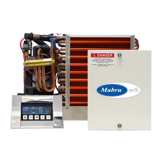
- Page 1 MARINE SELF-CONTAINED DIRECT EXPANSION AIR CONDITIONING SYSTEMS Installation Manual Models : · SC4.2 (Z) · SC4.2 (Z) DC · SC06 (Z) · SC06 (Z) DC · SC10 (Z) · SC10 (Z) DC · SC12 (Z) · SC12 (Z) DC · SC16 (Z)
- Page 2 Introduction Safety Precautions Safety Precautions Technical Parameters Outline Drawings Installation Overview Blower Rotation Placement of A/C Unit Ducting Seawater System Installation Checklist and Final Inspection Operation Controls and Display Remote Wiring Diagram Troubling Shooting...
- Page 3 hank you very much for purchasing our SC series marine self-contained air conditioning unit! Our company was determined to create an ISO9001 standard unit that surpassed our customer’s expectations by using only the best components known to outlast and out preform our vigorous quality standards. Higher fl...
-
Page 4: Safety Warning
VERY IMPORTANT SAFETY CONSIDERATIONS 1- Never install your air conditioner in the bilge or engine room areas. 2- Ensure that the selected location is sealed from direct access to bilge and/or engine room vapors. 3- Do NOT terminate condensate drain line within three feet of any outlet of engine or generator’s exhaust systems, nor in an engine or generator’s compartment housing, nor in a bilge, unless the drain is connected properly to a sealed condensate or shower sump pump. -
Page 5: Prior To Installation
PRIOR TO INSTALLATION, Please read these instructions completely and then plan all connections which must be made to the a/c unit including ducting, condensate drain line, seawater inlet and outlet hoses, electrical power connection, location of control and seawater pump placement, to assure easy access for routing and future servicing. INSTALLATION OVERVIEW: See Figure 1 for an overview of a typical SC a/c system installation. - Page 6 TECHNICAL PARAMETER LIST 1 (110V / 60Hz / 1 UNIT, AC BLOWER) Model No. SC4.2 (Z) SC06 (Z) SC10 (Z) SC12 (Z) SC16 (Z) Cooling capacity Btu/h 4200 6000 10000 12000 16000 Heating capacity Btu/h 4500 6500 11000 13500 17600...
- Page 7 TECHNICAL PARAMETER LIST 2 (220V / 60Hz / 1 UNIT, AC BLOWER) Model No. Model No. SC4.2 (Z) SC4.2 (Z) SC06 (Z) SC06 (Z) SC10 (Z) SC10 (Z) SC12 (Z) SC12 (Z) SC16 (Z) SC16 (Z) Cooling capacity Btu/h 4200...
- Page 8 TECHNICAL PARAMETER LIST 3 (110V / 60Hz / 1 UNIT, DC BLOWER) Model No. SC4.2 (Z) SC06 (Z) SC10 (Z) SC12 (Z) SC16 (Z) Cooling capacity Btu/h 4200 6000 10000 12000 16000 Heating capacity Btu/h 4500 6500 11000 13500 17600...
- Page 9 TECHNICAL PARAMETER LIST 4 (220V / 60Hz / 1 UNIT, DC BLOWER) Model No. SC4.2 (Z) SC06 (Z) SC10 (Z) SC12 (Z) SC16 (Z) Cooling capacity Btu/h 4200 6000 10000 12000 16000 Heating capacity Btu/h 4500 6500 11000 13500 17600...
- Page 10 Model No. W (in/mm) D (in/mm) H (in/mm) 4200BTU Model SC4.2/SC4.2Z/SC4.2DC/SC4.2ZDC 13.8/330.5 7.5/190.5 9.4/238 6000BTU Model SC06/SC06Z/SC06DC/SC06ZDC 15.6/396 9.4/239 11/279.4 10000BTU Model SC10/SC10Z/SC10DC/SC10ZDC 18.9/480 11.2/284 11.6/294.6 12000BTU Model SC12/SC12Z/SC12DC/SC12ZDC 18.9/480 11.2/284 11.6/294.6 16000BTU Model SC16/SC16Z/SC16DC/SC16ZDC 19.5/495 12.4/315 12.9/327.6...
- Page 11 FIGURE (1). Installation overview...
- Page 12 - Mount unit with condenser/evaporator coil directly behind return air grill or with at least 3” (76mm) of air circulation clearance if adjacent to a bulkhead or other obstructions. See Figure 2. - Compressor should be mounted away from return air grill if possible to minimize sound level in cabin.
- Page 13 NON-SLIP TAPE Put the attached non-slip tape on the base of the A/C system securely. See fi gure 4. FIGURE.4 NON-SLIP TAPE The four mounting brackets provided should be placed around edge of drain pan as equally spaced as possible. Secure a/c unit to a fl at level mounting surface.
- Page 14 Good airfl ow is critical for the performance of the entire system. It is highly dependent on the quality of the ducting installation. The ducting should be running as stright, smooth and taut as possible minimizing the number of 90° bends (two 90° bends can reduce the airfl ow by 25°).
- Page 15 Several guidelines should be followed during the installation of the seawater system.. If the circulation pump is centrifugal and not self-priming, it must be mounted so that it is always at least one foot below the water line regardless of which tank the vessel is on.
- Page 17 CHECK THE MARINE AIR CONDITIONER: - Check for any damage (appearance, inside pipes..etc) when transporting and handling. - Check if the fan’s motor is rotating normally. CHECK THE PIPING SYSTEM: Check if the system’s piping and valves are installed correctly. - Check if the ducts are loosened or not and if its insulations and drains are well done.
- Page 18 The buttons on the wire control are designed to switch the unit ON and OFF, increase/decrease the temperature, set the mode, set the timer, and control the fan’s speed. ON/OFF Press and release to turn the unit ON or OFF. MODE Press to choose through the modes of operation, MODE selections are COOL, HEAT and FAN.
- Page 19 Models No: SC4.2(Z) - SC06(Z) - SC10(Z) - SC12(Z) - SC16(Z)
- Page 20 Models No: SC4.2(Z)DC - SC06(Z)DC - SC10(Z)DC - SC12(Z)DC - SC16(Z)DC...
- Page 21 (OPTIONAL)
-
Page 22: Error Codes Table
The PCB controller will estimate the each error which happened in the system operation, and do the treatments according to these error types. The trouble shootings and errors go into four types, which are the unit resumed protection, system resumed protection, unit serious fault protection, and system serious fault protection. - Page 23 ERROR CODES TABLE Error Error Error Descriptions Error Descriptions Treatments Treatments Resumes Resumes Code Code Stop the machine, input the Stop the machine, input the correct passwords correct passwords Automatically resumed when Automatically resumed when (if it is beyond three times, (if it is beyond three times, Input the primary password by user Input the primary password by user...
- Page 24 Mabru Power Systems cannot accept responsibility for possible errors in catalogs, brochures and other printed material. Mabru Power Systems 1105 Old Griffi n Rd. | Dania Beach, FL 33004 Tel: 954-467-1770 Email: sales@mabrumarine.com www.mabrumarine.com...
Need help?
Do you have a question about the SC4.2 and is the answer not in the manual?
Questions and answers