Table of Contents
Advertisement
Quick Links
SP6 Installation and Setup V0.91
SP6 INSTALLATION AND SETUP MANUAL
Contents
1
SportDevices End User Software License & Warranty Disclaimer ........................................ 2
2
General Safety Instructions .................................................................................................... 3
2.1
SAFETY: When Working Inside Your Device ............................................................. 3
SAFETY: General Power Safety ................................................................................ 4
2.2
2.3
SAFETY: If Your Device Gets Wet ............................................................................. 4
2.4
SAFETY: If You Drop or Damage Your Equipment ..................................................... 5
Protecting Against Electrostatic Discharge ................................................................. 5
2.5
2.6
Dynamometer Important Safety Tips .............................................................................. 6
2.7
Technical Specs ............................................................................................................ 6
Input Specs .............................................................................................................. 6
2.7.1
2.7.2
Output Specs ........................................................................................................... 7
Connectivity Specifications ........................................................................................ 7
2.7.3
3
SP6 Installation .................................................................................................................. 8
3.1
Introduction ................................................................................................................ 8
Dynamometer Installation. ............................................................................................ 8
3.2
3.2.1
Vehicle dynamometers ............................................................................................. 8
3.2.2
2WD single / double roller dynamometer .................................................................... 9
3.2.3
Single roller AWD dynamometer: ............................................................................. 10
3.2.4
Twin roller AWD dynamometer: ............................................................................... 11
3.2.5
HUB-2 Dynamometer .............................................................................................. 12
3.2.6
HUB-4 Dynamometer .............................................................................................. 13
3.2.7
Engine Test bed dyno installation ............................................................................. 14
3.3
Proposed installation parts. ......................................................................................... 15
SP6 Connections ........................................................................................................ 16
3.4
3.4.1
SP6 Front Panel ...................................................................................................... 16
3.4.2
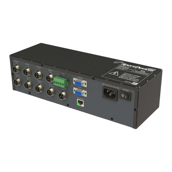
SP6 Rear Panel ....................................................................................................... 18
4
SportDyno Quick Setup Guide .............................................................................................. 22
4.1
Inertial Configuration: Roller / Flywheel ........................................................................ 22
4.2
Ratio Configuration .................................................................................................... 23
4.3
Load Cell Calibration ................................................................................................... 24
4.4
Speed Control Configuration (SP4-SP6) ......................................................................... 25
Sportdevices © 2019
20/NOV/2019
Advertisement
Table of Contents

Related Manuals for Sportdevices SP6

Summary of Contents for Sportdevices SP6
-
Page 1: Table Of Contents
SP6 Installation and Setup V0.91 Sportdevices © 2019 SP6 INSTALLATION AND SETUP MANUAL Contents SportDevices End User Software License & Warranty Disclaimer ........2 General Safety Instructions ....................3 SAFETY: When Working Inside Your Device ............. 3 SAFETY: General Power Safety ................4 SAFETY: If Your Device Gets Wet ................ -
Page 2: Sportdevices End User Software License & Warranty Disclaimer
To the maximum extent permitted by applicable law, neither SportDevices, its dealers or suppliers shall have any liability to you or any other person or entity for any indirect, incidental, special, or consequential damages whatsoever, including, but not limited to, loss of revenue or profit, lost or damaged data or other commercial or economic loss, even if SportDevices. -
Page 3: General Safety Instructions
2.1 SAFETY: When Working Inside Your Device Do not attempt to service the equipment yourself, except as explained in your documentation or in instructions otherwise provided to you by SportDevices. Always follow installation and service instructions closely. 20/NOV/2019... -
Page 4: Safety: General Power Safety
Sportdevices © 2019 SAFETY: General Power Safety By default, if other values are not specified all SportDevices equipment are rated for 230 VAC / 50 Hz. (115 VAC units will have a specific label for that) Observe the following guidelines when connecting your equipment to a power source: Check the voltage rating before you connect the equipment to an electrical outlet to ... -
Page 5: Safety: If You Drop Or Damage Your Equipment
4. Connect the device to the power source and turn on the device. 5. If the device does not start, or if and smoke or unusual odors are detected, or you cannot identify the damaged components, contact SportDevices support. Protecting Against Electrostatic Discharge CAUTION: Disconnect product from mains power source in accordance with product specific safety information located on the “Safety Information”... -
Page 6: Dynamometer Important Safety Tips
SP6 Installation and Setup V0.91 Sportdevices © 2019 Dynamometer Important Safety Tips Securely fasten test vehicle using all available restraining ratchet straps. The more straps the better. Secure both front to back and side to side. Never move the steering wheel for front wheel drive vehicles while under test. -
Page 7: Output Specs
SP6 Installation and Setup V0.91 Sportdevices © 2019 SportDyno Software allows the usage on an External analog card (through CANBUS or MODBUS), for example DEIF CIO308 (CANBUS) provides 8 extra channels that can be configured in several scales for voltage, current or resistance measurement. -
Page 8: Sp6 Installation
Brake Control output channel SP6 can be used to automate most functions on a dyno room (engine test bed) or to control a vehicle dynamometer (rolling road or hub dyno). It has several inputs and outputs to acquire data from the engine and to control the brake(s) and other parts of the installation. -
Page 9: 2Wd Single / Double Roller Dynamometer
SP6 Installation and Setup V0.91 Sportdevices © 2019 Most sensors/devices are connected typically to SP6: Lambda (with external controller) Thermocouples (water, exhaust, etc) (up to 8) Other analog signals (up to 8) Remote control But other devices are connected directly to Computer: USB Weather Station ... -
Page 10: Single Roller Awd Dynamometer
SP6 Installation and Setup V0.91 Sportdevices © 2019 3.2.3 Single roller AWD dynamometer: In single roller AWD dynamometers each axle has its own hall sensor, load cell, and power supply + brake using F1 and R1 channels, as shown in the picture. -
Page 11: Twin Roller Awd Dynamometer
Optionally SP6 could use the same configuration as 2WD twin roller dynamometers (roller channels F2 and R2) in order to measure speed at rear-subaxes (not braked), even with the SP6 AWD version (2 load cells), since the rear sub-axles are not braked and do not need a load cell. -
Page 12: Hub-2 Dynamometer
Sportdevices © 2019 3.2.5 HUB-2 Dynamometer When using SP6 AWD/HUB-2 version for a HUB-2 dyno it is important to realize that only channels F1 and R1 are complete: rollers F2 and R2 can be used for auxiliary rollers, but cells F2 and R2 do not exist. Thus when using the DAQ with a HUB-2 dynamometer only “front”... -
Page 13: Hub-4 Dynamometer
Sportdevices © 2019 3.2.6 HUB-4 Dynamometer HUB-4 Dynamometer can only be implemented using SP6-HUB-4 version since it is the only one that implements the 4 load cells and has the 4 brakes sync active (HUB-2 version will not have it active). In the next picture CAN IDs are shown to ease the PWS connections. -
Page 14: Engine Test Bed Dyno Installation
Typically only channels F1 (roller F1 and cell F1) will be used. As SP6 2WD still have two load cell inputs, this feature can be used to control 2 dynamometers with a single DAQ using two SportDyno profiles. For instance a 2WD dynamometer with channels F1, and... -
Page 15: Proposed Installation Parts
(as turning the engine ignition OFF) it is recommended to have an extra switch in series, at the control room. Nevertheless it is not recommended to install either SP6 or power supplies directly over the chassis as they are not rated for strong vibrations Proposed installation parts. -
Page 16: Sp6 Connections
Red led, normally OFF. If ON it means that there is some error at initialization. If blinking it may mean that 12V power supply is faulty. Green led: normally shows the SP6 activity blinking at different speeds 3.4.1.1 Roller / Brake Front1, Front2, Rear1, Rear2 Connectors 1 –... - Page 17 SP6 Installation and Setup V0.91 Sportdevices © 2019 3.4.1.2 Cell Front1, Front2, Rear1, Rear2 Connectors 1 – Cell (-), SP6 uses up to four 24-bit ADCs with built-in amplifier (in the HUB-4 version) 2 - GND 3 – 5V (max 50 ma total) 4 –...
-
Page 18: Sp6 Rear Panel
12 volt relays / 100 ohm approx. The maximum power deliverable by the SP6 is 1.5A, this means that low consumption relays should be used, but they can be operated all at a time (while SP5 had restrictions with the max number of relays) - Page 19 3.4.2.3 PWM outputs PWM signals are replicated at back side to ease the installation of SP6 and PWS, in order to avoid using the “T-cables” that split the signal from 5-pin connectors between hall sensor and PWS (as in SP5) 1 –...
- Page 20 PWS3.x and HS-PWS: Recently we have added CANBUS to PWS3.x and HS-PWS: connect this to SP5/SP6 PWS CANBUS. In case of several PWS (AWD dyno or HUB-4) the last PWS in the bus must have the terminator ON, the rest terminator OFF / jumper removed.
- Page 21 Sportdevices © 2019 PWS1.5: IMPORTANT: Do not use 5V, I/P and GND lines, these lines are not isolated from mains line and will cause severe damage to SP6 or computer. They are only used for testing purposes (non isolated potentiometer) 20/NOV/2019...
-
Page 22: Sportdyno Quick Setup Guide
Number of Teeth for gear tooth. Note: recommended from 80 to 150 teeth Prescaler: always 1 for SP6 (please note that SP6 can internally have a HW prescaler from 1 to 16 to allow the usage of encoders) Set “SP6 mode”... -
Page 23: Ratio Configuration
Sportdevices © 2019 Ratio Configuration Ratio is a key parameter which is used on several processes of Sportdyno, and also on SP6 for speed control: It is used to convert Roller Torque to Engine Torque. Due to the gearbox torque ... -
Page 24: Load Cell Calibration
SP6 Installation and Setup V0.91 Sportdevices © 2019 Load Cell Calibration Load cell calibration consists of applying a known weight on a calibration arm at the brake. But first of all, the cell has to be “zeroed” when it has no weight. Then the program is able to use the difference from the digital reading between the no-load condition and the loaded condition to perform the calibration. -
Page 25: Speed Control Configuration (Sp4-Sp6)
SP6 implements a standard PID, with I constant proportionally to P (Kp) Ti, this allows changing only Kp constant and SP6 will modify Ki to keep the same dynamic behavior. (Ki = Kp * 1 / Ti) SP6 does not implement a Kd derivative constant, but it implements a more sophisticated overshoot control. - Page 26 SP6 Installation and Setup V0.91 Sportdevices © 2019 A good starting point for PID setup is: Kp = 1 (1 to 2 for motorcycles, or 10-15 for car dyno, it may be higher) Ti = 0.5-1 (max recommended 0.3 to 1.0) Overshoot = 0 (Td / derivative control) Kp basically controls the speed control reaction time.
Need help?
Do you have a question about the SP6 and is the answer not in the manual?
Questions and answers