Table of Contents

Related Manuals for Terofire Products Plus

Summary of Contents for Terofire Products Plus
- Page 1 Terofire Plus User & Installation Manual IMPORTANT This manual should be left with the panel after installation. We reserve the right to change product specifications without prior notice. Copyright © Terofire Products 1999.
-
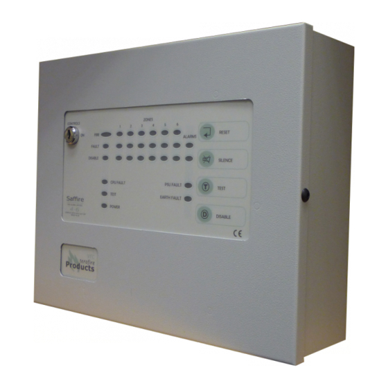
Page 2: General Description
2-12 sense zones (detector zones). The Terofire 12 is provided with 4 alarm zones (bell zones) while the other panels in the range have 2 alarm zones. All Terofire Plus panels have a one man test facility, class change input, fault output and two sets of volt free changeover contacts which operate on fire. - Page 3 Detector Head Removal The Terofire Plus range supports head removal. The basic principle of head removal is to ensure that all call points will function even if a detector head has been removed. When a detector head is removed, the panel will show a fault but the sense zone circuit will remain intact.
-
Page 4: Panel Operation
Terofire Products Panel Operation Enabling the front panel buttons. Before being able to access the Reset, Silence, Evacuate and Test functions, the key switch in the top left of the panel must be turned through 90° to the ON position. - Page 5 Terofire Plus Instruction Manual The test lamp will light as soon as a zone is placed in test mode. Placing too many zones at once in test mode will leave the building without adequate protection. When a zone in test mode detects a fire condition, the alarms will ring for approximately three seconds before resetting.
-
Page 6: Fault Finding
Terofire Products Fault Finding Front panel buttons not working. To activate the front panel buttons turn the keyswitch in the top left of the panel through 90° to the ON position. Fault lamp and zone fault lamp flashing, internal buzzer sounding. - Page 7 Terofire Plus Instruction Manual CPU Fault lamp lit, internal buzzer sounding. The processor has stopped running its program. If no problems are found then reset the processor. Inside the panel on the main circuit board are two push buttons marked CPU RESET (SW1) and W/D RESET (SW2).
-
Page 8: Panel Specifications
Terofire Products Panel Specifications e l i ± a i l Please ensure all calculations take into account the startup current of the devices used. This is especially important if you intend to use xenon beacons. - Page 9 Terofire Plus Instruction Manual ± ± ± ±...
- Page 10 Terofire Products...
- Page 11 Terofire Plus Instruction Manual Sense Zone Wiring Diagrams Find the detector bases you will be using in the table on page 10 and check to see which end of line device is required - either a 3k3 resistor or an active end of line unit. The 3k3 resistor should be used if a zone is comprised entirely of call points.
- Page 12 Terofire Products Alarm Zone Wiring Diagrams The alarm zones are wired as in the diagram below. A 10k end of line resistor must be fitted at the end of the circuit. Motorised fire bells may be used, but solenoid bells MUST NOT be connected to the panel.
- Page 13 Terofire Plus Instruction Manual Additional Wiring Information Connecting a relay to the auxiliary fault (AF) output. A fault relay can be connected to the panel as shown. The diode (1N4001 or equivalent) must be fitted. The relay must have a 24V DC coil.
- Page 14 Terofire Products Signalling fire to another panel. By connecting two panels as shown below, when panel B closes its auxiliary contacts, panel A will go into fire. If the zone on panel A is set to non-latching it will automatically reset when panel B opens its auxiliary contacts.
- Page 15 Terofire Plus Instruction Manual Terofire System Log Book All events should be properly recorded in this log book. An ‘event’ should include fire alarms (whether real or false), faults, tests, temporary disconnections and the dates of installing or servicing engineer’s visits with a brief note of work carried out and outstanding.
- Page 16 Terofire Products t i n...