
Related Manuals for ComCo Systems 521 Series


Summary of Contents for ComCo Systems 521 Series
- Page 1 Series Installation and Operator Manual ComCo Systems Inc. | 800.533.3794 www.comcosystems.com 500169 Rev. 18.0...
- Page 2 This publication contains materials protected by copyright. No part of this publication may be reproduced in any form or used as the basis for the sale or manufacture of apparatus without prior written consent by ComCo Systems. ©2018 ComCo Systems INC All rights reserved Some of the materials and applications described in this publication may be protected under one or more of the following US patents: DES272076, 4180354, 4971481, 4984939, 5584613, 6039510, or other Patents Pending.
-
Page 3: Table Of Contents
Contents Series System Features 521A Teller Unit 521 Single/Dual Sided Teller Unit Customer Unit Blower System Controller 521 EZ Station Operation 521A Teller Unit Operations Specification Parts List 521 Single/Dual Sided Teller Unit Operations Specification Parts List 521 EZ Master Station Cut Sheet Riser Diagram Wiring Diagram... -
Page 4: System Features
Teller operating unit which is Teller operating unit which suspended from the ceiling, typically Doorless stand alone unit is suspended over the counter top. with optional 2 way video. above the countertop 3 pg. ComCo Systems Inc. | 800.533.3794 | www.comcosystems.com 500169 Rev. 18.0... - Page 5 Series 521A Teller Unit TU-521-201194 Model: pg. 4 800.533.3794 | www.comcosystems.com 500169 Rev.18.0...
-
Page 6: Operation
Operation Series 1. System Power On/Off Switch 2. Control Panel Send Carrier Retrieve Carrier to Customer from Customer 5 pg. ComCo Systems Inc. | 800.533.3794 | www.comcosystems.com 500169 Rev. 18.0... -
Page 7: Operations
Operation Series 521A Teller Unit (TU) (P/N: 201194) Switch Operating Instructions ON/OFF Power cycles the complete system (Inside Unit, Outside Unit & Blowers). Power ON the system power light will be present. Power OFF means complete system power down. If installed it will power down the Customer Video Module (CVM). -
Page 8: Specification
Specification Series 521A Teller Unit (TU) (P/N: 201194) Dimensional & Electrical Specifications 7 pg. ComCo Systems Inc. | 800.533.3794 | www.comcosystems.com 500169 Rev. 18.0... -
Page 9: Specification
Specification Series 521A Teller Unit (TU) (P/N: 201194) Dimensional Cont. pg. 8 800.533.3794 | www.comcosystems.com 500169 Rev.18.0... - Page 10 Installation Series 521A System (P/N: 201194) System riser details 9 pg. ComCo Systems Inc. | 800.533.3794 | www.comcosystems.com 500169 Rev. 18.0...
- Page 11 Specification Series 521A with 521CU System (P/N: 201194) Field wiring Specifications pg. 10 800.533.3794 | www.comcosystems.com 500169 Rev.18.0...
- Page 12 Specification Series 521A with 522CU System (P/N: 201194) Field wiring Specifications 11 pg. ComCo Systems Inc. | 800.533.3794 | www.comcosystems.com 500169 Rev. 18.0...
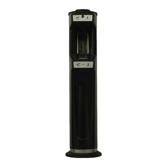
- Page 13 Series 521 Teller Unit Manual & Motorized TU-521-200501/200502 Model: pg. 12 800.533.3794 | www.comcosystems.com 500169 Rev.18.0...
- Page 14 The 521 teller terminal utilizes an automatic or manual door design. Insert the carrier in the unit and press Send. Carrier dispatches to the customer unit. 1. System Power On/Off Switch 2. Control Panel System Power Indicator LED Send Carrier Retrieve Carrier to Customer from Customer 13 pg. ComCo Systems Inc. | 800.533.3794 | www.comcosystems.com 500169 Rev. 18.0...
- Page 15 Operation Series 521 Teller Unit (TU) (P/N: 200501/200502) Switch Operating Instructions Fig. 1.0 ON/OFF Power cycles the complete system (Inside Unit, Outside Unit & Blowers). Power ON the system power light will be present. Power OFF means complete system power down. If installed it will power down the Customer Video Module (CVM).
- Page 16 Specification Series 521 Teller Unit (TU) (P/N: 200501/200502) Dimensional & Electrical Specifications 15 pg. ComCo Systems Inc. | 800.533.3794 | www.comcosystems.com 500169 Rev. 18.0...
- Page 17 Part Series 521 Teller Unit (TU) (P/N: P/N: 200501/200502 Parts Breakaway: pg. 16 800.533.3794 | www.comcosystems.com 500169 Rev.18.0...
- Page 18 Parts Series 521 Teller Unit (TU) P/N: 200501/200502 Parts Descriptions: 17 pg. ComCo Systems Inc. | 800.533.3794 | www.comcosystems.com 500169 Rev. 18.0...
- Page 19 Installation Series 521 Teller Unit Installation Detail Switch Bend pg. 18 800.533.3794 | www.comcosystems.com 500169 Rev.18.0...
- Page 20 Installation Series 521 Teller Unit Installation Detail Check Valve Bend 19 pg. ComCo Systems Inc. | 800.533.3794 | www.comcosystems.com 500169 Rev. 18.0...
-
Page 21: 521 Ez Master Station
Series 521 EZ MASTER STATION TU-521-201057 Model: pg. 20 800.533.3794 | www.comcosystems.com 500169 Rev.18.0... - Page 22 Specification Series 521EZ with 521CU System (P/N: 201057) Field wiring Specifications 21 pg. ComCo Systems Inc. | 800.533.3794 | www.comcosystems.com 500169 Rev. 18.0...
- Page 23 Installation Series 521EZ System (P/N: 201057) Dimensional & Electrical Specifications pg. 22 800.533.3794 | www.comcosystems.com 500169 Rev.18.0...
- Page 24 Installation Series 521EZ System (P/N: 201057) System Riser Details 23 pg. ComCo Systems Inc. | 800.533.3794 | www.comcosystems.com 500169 Rev. 18.0...
-
Page 25: Customer Unit
Series Customer Unit CU-521-200500 Model: pg. 24 800.533.3794 | www.comcosystems.com 500169 Rev.18.0... -
Page 26: Operations
(NOTE: DO NOT INSERT LOOSE ITEMS DIRECTLY INTO UNIT) CALL Generates an audible tune at the Teller Center when depressed. Upper Switch Panel (P/N: 200573) Lower Switch Panel (P/N: 200574) 25 pg. ComCo Systems Inc. | 800.533.3794 | www.comcosystems.com 500169 Rev. 18.0... -
Page 27: Specification
Specification Series Customer Unit (P/N: 200500) Dimensional & Electrical Specifications Item Measurements Value Customer Video Module Nominal Voltage 12 VDC (CV-100-200203) Current (max) 1.2 amps UNDERGROUND CONDUIT AT OWNER’S DISCRETION WITH OPTIONAL 2 WAY VIDEO 6.4” OR 10” CVM pg. 26 800.533.3794 | www.comcosystems.com 500169 Rev.18.0... -
Page 28: Installation
Installation Series Customer Unit (P/N: 200500) Mounting & Access 5. CONNECT UNDERGROUND WIRING IF AVAILABLE 27 pg. ComCo Systems Inc. | 800.533.3794 | www.comcosystems.com 500169 Rev. 18.0... - Page 29 Parts Series Customer Unit (P/N: 200500) Parts Breakaway: pg. 28 800.533.3794 | www.comcosystems.com 500169 Rev.18.0...
- Page 30 Part Series Customer Unit (P/N: 200500) Parts Descriptions: 29 pg. ComCo Systems Inc. | 800.533.3794 | www.comcosystems.com 500169 Rev. 18.0...
- Page 31 Series Single Pack Blower BM-200-200217 Model: pg. 30 800.533.3794 | www.comcosystems.com 500169 Rev.18.0...
- Page 32 1-115 VAC 0.5A Resettable Fuse 1-24 VAC 1.5A Resettable Fuse Class 2 Field Use ¼” minimum hardware to mount unit in place. For mounting location see cut sheets for job site. 31 pg. ComCo Systems Inc. | 800.533.3794 | www.comcosystems.com 500169 Rev. 18.0...
- Page 33 Parts Series Single Pack Blower Module (P/N: 200217) Parts Breakaway: pg. 32 800.533.3794 | www.comcosystems.com 500169 Rev.18.0...
- Page 34 Series Parts Single Pack Blower Module (P/N: 200217) Parts Breakaway: 33 pg. ComCo Systems Inc. | 800.533.3794 | www.comcosystems.com 500169 Rev. 18.0...
- Page 35 Parts Series Single Pack Blower Module (P/N: 200217) Parts Descriptions: pg. 34 800.533.3794 | www.comcosystems.com 500169 Rev.18.0...
-
Page 36: Specification
Specification Series Single Pack Blower Unit (P/N: 200217) Dimensional & Electrical Specifications 35 pg. ComCo Systems Inc. | 800.533.3794 | www.comcosystems.com 500169 Rev. 18.0... -
Page 37: Glossary Of Terms
Specification Series Glossary of Terms Customer Unit: Customer operating unit which is typically mounted outside on an island for the customer to drive up next to. This is the unit the customer uses to send the carrier to the teller. Teller Unit: Teller operating unit which is suspended from the ceiling, typically over the counter top. - Page 38 The contents of the carrier must be fully within the carrier and not caught between edges. Multiple transmissions should be used if a load is too large to fit within the single carrier. 37 pg. ComCo Systems Inc. | 800.533.3794 | www.comcosystems.com 500169 Rev. 18.0...
- Page 39 Series Theory of Operation Powering the System The green pushbutton on the left side of the teller unit control panel controls power to the entire system. Within the switch is a green LED that indicates “power on.” Power ON 1. Teller switches power on 2.
- Page 40 11. Automatic Teller Units only: Teller Unit door opens 12. Manual Teller Units only: teller opens Teller Unit door 13. Recall cycle ends – system is now in ready state 39 pg. ComCo Systems Inc. | 800.533.3794 | www.comcosystems.com 500169 Rev. 18.0...
- Page 41 Installation Series Installation Control Field Wiring Diagram (P/N: 500136) NOTE: All Class 2 interconnecting cabling must be done in compliance with the ARTICLE 800.33 (A) FPN No.2, exception No.2, of the NEC (National Electrical Code) by an authorized/qualified personnel. pg. 40 800.533.3794 | www.comcosystems.com 500169 Rev.18.0...
- Page 42 Installation Series Installation Optional CVM Field Wiring Diagram (P/N: 500073) 41 pg. ComCo Systems Inc. | 800.533.3794 | www.comcosystems.com 500169 Rev. 18.0...
- Page 43 Installation Series Installation Optional CVM Field Wiring Diagram (P/N: 500073-2) pg. 42 800.533.3794 | www.comcosystems.com 500169 Rev.18.0...
- Page 44 Installation Series System Riser Diagram & Options Parts Descriptions: 43 pg. ComCo Systems Inc. | 800.533.3794 | www.comcosystems.com 500169 Rev. 18.0...
- Page 45 Installation Series Specification Detail Valve & Switch Bend pg. 44 800.533.3794 | www.comcosystems.com 500169 Rev.18.0...
- Page 46 Installation Series Installation Detail Check Valve and Nipple Bend 45 pg. ComCo Systems Inc. | 800.533.3794 | www.comcosystems.com 500169 Rev. 18.0...
- Page 47 Installation Series Special Installation Procedures Customer Unit The deceleration trigger must be installed in the horizontal orientation shown in drawing #0520033A in order to function properly. If it is not installed in the correct orientation, the carrier may land hard at the customer unit.
-
Page 48: Carriers
Carriers should be inspected regularly for signs of wear. Carriers landing hard at either customer or teller unit may be a sign of worn air discs or rubbing bands on carrier. Replace air discs and/or rubbing bands as required. 47 pg. ComCo Systems Inc. | 800.533.3794 | www.comcosystems.com 500169 Rev. 18.0... - Page 49 Maintenance Series pg. 48 800.533.3794 | www.comcosystems.com 500169 Rev.18.0...
- Page 50 Teller Unit Wall Bracket 200148 521 CU Escutcheon Plate Kit 200727 521/522 CU Escutcheon Hardware Kit 400253 Base Trim 613801 Flex Hose 200186 Tube Metal Sealant 500169 Installation Manual 49 pg. ComCo Systems Inc. | 800.533.3794 | www.comcosystems.com 500169 Rev. 18.0...
- Page 51 Appendix B Series 521 Spare Parts List Teller Unit Mechanical Components Usage 200037-1 Door cable – manual teller 200037-2 Door cable – automatic teller 611609 Spring – door cable tension 611606 Spring – pulley tension 200138-1 Door assembly – manual teller 200138-2 Door assembly –...
- Page 52 Kit Assembly Decel Replacement Parts Carriers 602033 Carrier – 4.5” end-opening 602013 Air ring – 4.25 3-ply – 4.50 EO carrier 602052 Wear band – Velcro – 4.5” (2 per carrier) 51 pg. ComCo Systems Inc. | 800.533.3794 | www.comcosystems.com 500169 Rev. 18.0...
- Page 53 Lake Dallas, TX. 75065 RMA# XXXX All RMAs will be processed in the order they are received. ComCo Systems will not accept any returns that do not have an RMA# assigned. To check on the status of an RMA email or call our Customer Service Representatives with your RMA#.
- Page 54 Parts Orders parts@comcosystems.com 800.533.3794 Option 2 • Equipment and System Sales sales@comcosystems.com 800.533.3794 Option 3 • Project Management 800.533.3794 Option 4 • Accounting accounting@comcosystems.com 800.533.3794 Option 5 https://www.facebook.com/ComcoSystems https://twitter.com/comcosystems 53 pg. ComCo Systems Inc. | 800.533.3794 | www.comcosystems.com 500169 Rev. 18.0...
Need help?
Do you have a question about the 521 Series and is the answer not in the manual?
Questions and answers