
Related Manuals for ComCo Systems 621 Series


Summary of Contents for ComCo Systems 621 Series
- Page 1 Series Pharmacy Installation and Operator Manual ComCo Systems Inc. | 800.533.3794 www.comcosystems.com 500648 Rev. A...
- Page 2 This publication contains materials protected by copyright. No part of this publication may be reproduced in any form or used as the basis for the sale or manufacture of apparatus without prior written consent by ComCo Systems. ©2020 ComCo Systems INC All rights reserved Some of the materials and applications described in this publication may be protected under one or more of the following US patents: DES272076, 4180354, 4971481, 4984939, 5584613, 6039510, or other Patents Pending.
-
Page 3: Table Of Contents
13 Operations Specification Theory of Operation pg. 14 Installation pg. 16 System Setup and Installation Field Wiring Diagram Maintenance and Cleaning pg. 23 Troubleshooting pg. 24 Replacement Parts pg. 25 ComCo Systems Inc. | 800.533.3794 | www.comcosystems.com 500648 Rev A... -
Page 4: System Features
Manual operated door unit, which is suspended from the ceiling, typically over countertop. Dual Pack UL Blowers 200217-2(x2) Features: 2 Power Cords 2 115Vac/15A 2 Blowers for pressure 2 Blowers for vacuum ComCo Systems Inc. | 800.533.3794 | www.comcosystems.com 500648 Rev. A... -
Page 5: 621 Manual Operator Unit
Series Operator Unit TU-621-201314 Model: ComCo Systems Inc. | 800.533.3794 | www.comcosystems.com 500648 Rev A... -
Page 6: Operation
To resume operation close door and press RECALL or SEND. Please note the reference guide in Fig. 1.0. Fig. 1.0 ComCo Systems Inc. | 800.533.3794 | www.comcosystems.com 500648 Rev. A... -
Page 7: Operations
RECALL Recalls a carrier from the customer unit. The operator unit door must be closed in order to recall a carrier from the customer unit. ComCo Systems Inc. | 800.533.3794 | www.comcosystems.com 500648 Rev A... -
Page 8: Specification
Dimensional & Electrical Specifications Item Measurements Value Operator Unit Nominal Voltage 24 VAC From Blower (TU-621-200430-1) Current (max) 1 Amp System Controller (P/N: 200155K) See Appendix A For System Settings ComCo Systems Inc. | 800.533.3794 | www.comcosystems.com 500648 Rev. A... -
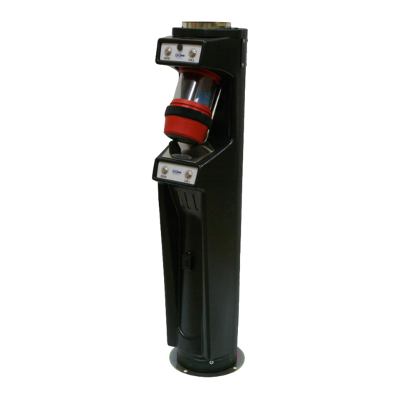
Page 9: 621 Customer Unit
Series Customer Unit CU-621-201315 Model: ComCo Systems Inc. | 800.533.3794 | www.comcosystems.com 500648 Rev A... -
Page 10: Operations
Machine & Switch Operating Instructions SEND Sends carrier to Teller Unit. CALL Generates audible tone at the Pharmacy when depressed. Top Switch Plate (P/N: 201327) Bottom Switch Plate (P/N: 201328) ComCo Systems Inc. | 800.533.3794 | www.comcosystems.com 500648 Rev. A... -
Page 11: Specification
Dimensional & Electrical Specifications Item Measurements Value Customer Video Module Nominal Voltage 12 VDC (CVM-2000-200903-10) Current (max) 3.5 Amps 1520 Lane Station Nominal Voltage 12 VDC (600651) Current (max) 1.5 Amps ComCo Systems Inc. | 800.533.3794 | www.comcosystems.com 500648 Rev A... -
Page 12: Dual Blowers
Series Dual Pack Blower 200217-2(x2) Model: ComCo Systems Inc. | 800.533.3794 | www.comcosystems.com 500648 Rev. A... - Page 13 2-115 VAC 0.5 A Resettable Fuse 2-115 VAC 1.5 A Resettable Fuse Class 2 Field Wiring Use ¼” minimum hardware to mount unit in place. For mounting location see cut sheets for job site. ComCo Systems Inc. | 800.533.3794 | www.comcosystems.com 500648 Rev A...
-
Page 14: Specification
The contents of the carrier must be fully within the carrier and not caught between edges. Multiple transmissions should be used if a load is too large to fit within the single carrier. ComCo Systems Inc. | 800.533.3794 | www.comcosystems.com... -
Page 15: Theory Of Operation
7. Carrier passes Deceleration Switch Tube over Customer Unit 8. Pressure blower deactivates 9. Carrier decelerates due to Solenoid engaging 10. Solenoid timer waits for Carrier to land. 11. Send cycle ends; System is now in ready state ComCo Systems Inc. | 800.533.3794 | www.comcosystems.com 500648 Rev A... - Page 16 8. Carrier is decelerated by pressure ahead of carrier (valve in Check Valve blocks pressure from Operator Unit) 9. Carrier arrives at Operator Unit. 10. Cycle timer times out 11. Recall cycle ends – system is now in ready state ComCo Systems Inc. | 800.533.3794 | www.comcosystems.com 500648 Rev. A...
-
Page 17: Installation
Installation Series Cut Sheets NOTE: ComCo Systems Inc. | 800.533.3794 | www.comcosystems.com 500648 Rev A... - Page 18 Installation Series Cut Sheets NOTE: ComCo Systems Inc. | 800.533.3794 | www.comcosystems.com 500648 Rev. A...
- Page 19 Installation Series Cut Sheets NOTE: ComCo Systems Inc. | 800.533.3794 | www.comcosystems.com 500648 Rev A...
-
Page 20: Field Wiring Diagram
Installation Series Field Wiring Diagram (D/N: 5006) NOTE: Deceleration switches MUST be wired in Parallel ComCo Systems Inc. | 800.533.3794 | www.comcosystems.com 500648 Rev. A... - Page 21 Installation Series Control/Audio Field Wiring Diagram (D/N: 500073) NOTE: Refer to Audio Authority Manual for Audio Installation ComCo Systems Inc. | 800.533.3794 | www.comcosystems.com 500648 Rev A...
- Page 22 Installation Series System Riser Diagram & Options Parts Descriptions: ComCo Systems Inc. | 800.533.3794 | www.comcosystems.com 500648 Rev. A...
- Page 23 (this should be 2-3 seconds after the carrier lands at the teller unit). See Appendix A for switch settings and other timing settings. ComCo Systems Inc. | 800.533.3794 | www.comcosystems.com 500648 Rev A...
-
Page 24: Maintenance And Cleaning
The carrier is to be cleaned with alcohol wipes containing no more than 75% Isopropyl Alcohol. Customer Unit & Operator The Operator and Customer unit are to be cleaned with alcohol wipes containing no more than 75% Isopropyl Alcohol. ComCo Systems Inc. | 800.533.3794 | www.comcosystems.com 500648 Rev. A... -
Page 25: Troubleshooting
• Verify carriers are in good condition. • Ensure that the solenoid is engaging at end of cycle. Check that I7 LED is turning on at end of cycle. Refer to Appendix A for LED details. ComCo Systems Inc. | 800.533.3794 | www.comcosystems.com 500648 Rev A... -
Page 26: Replacement Parts
Description Part Number Usage per Lane Upper Switch Plate 201327 Lower Switch Plate 201328 Rubber Bumpers 605204 Microphone Assembly 200746 Speaker Assembly 200067 Main Harness 200665 1520 Interface Harness 200880 ComCo Systems Inc. | 800.533.3794 | www.comcosystems.com 500648 Rev. A... - Page 27 10 Amp Circuit Breaker 604412 Solenoid Assembly 200282 Carriers Description Part Number Usage per Lane 6” Single End Opening Carrier 602124 Misc. Description Part Number Usage per Lane Deceleration Switch 200599 ComCo Systems Inc. | 800.533.3794 | www.comcosystems.com 500648 Rev A...
- Page 28 Series Appendix A ComCo Systems Inc. | 800.533.3794 | www.comcosystems.com 500648 Rev. A...
Need help?
Do you have a question about the 621 Series and is the answer not in the manual?
Questions and answers