Table of Contents
Advertisement
Quick Links
Advertisement
Table of Contents

Subscribe to Our Youtube Channel
Related Manuals for TrojanLabel T3-OPX

Summary of Contents for TrojanLabel T3-OPX
- Page 1 T3-OPX user guide Version 1.2...
-
Page 2: Table Of Contents
1.5.2 The machine’s purpose and intended use ................9 1.5.3 Warning about foreseeable misuse ................... 9 1.5.4 Specifications T3-OPX ......................10 1.5.5 Specifications MailTable 1 (MT1) .................... 13 1.5.6 Specifications MailTable 2 (MT2) .................... 14 T3 OPX physical overview ........................15 Front side ............................ - Page 3 Shutdown ............................45 Exporting statistics data to a CSV file/ viewing statistics from a browser ........46 Transferring print jobs to the T3-OPX using the Xitron RIP ..............48 Starting the Xitron RIP Server ......................48 Transferring a job from the web client .................... 48 5.2.1...
- Page 4 Aerosol filter replacement process ..................72 RIP installation (XITRON) ........................73 12.1 Link TrojanControl ........................... 73 12.2 Installing just the client ........................74 Debugging connections........................75 13.1 Controls for T1030 (webpath board) ....................76 Revision history ........................... 77 T3-OPX installation Page | 3...
- Page 5 T3-OPX installation Page | 4...
-
Page 6: Specification And General Information
1 Specification and general information 1.1 Certificate and Compliance T3-OPX specific CFR Title 47 Part 15 Subpart B (2020) ISED ICES-003 Issue 6 Published 2016 Updated 2019 CENELEC EN 55024:2011+A1:2015, CISPR 35:2016Ed.1.0 CENELEC EN 55032:2015, CISPR 32:2015 CENELEC EN 61000-3-2:2014, IEC 61000-3-2 Ed 5:2018 CENELEC EN 61000-3-3:2008, IEC 61000-3-3 Ed 3.1:2017... -
Page 7: Emissions
1.1.1 Emissions T3-OPX installation Page | 6... -
Page 8: Warning Symbols
Engravement in English T3-OPX installation Page | 7... -
Page 9: Introduction
1.3 Introduction 1.3.1 Original instructions These instructions are original instructions made by Trojanlabel for the Trojanlabel digital over-printer T3-OPX. 1.3.2 Purpose The purpose of these instructions is to ensure correct installation, use, handling and maintenance of the machine. 1.3.3 Accessibility The instructions are to be kept in a location known to the staff and must be easily accessible for the operators and maintenance personnel. -
Page 10: Specification And Application
The machine must not be used for any other purpose than the purpose mentioned above. 1.5.3 Warning about foreseeable misuse The T3-OPX may not be used with inks not endorsed by Trojanlabel. All inks purchased from Trojanlabel or from official Trojanlabel distributors worldwide are endorsed by Trojanlabel. T3-OPX installation... -
Page 11: Specifications T3-Opx
1.5.4 Specifications T3-OPX Operation Ink Type Pigmented ink, 4 Individual CMYK cartridges Resolution High Resolution Mode: 1200 x 1200 optimized dpi from 600 x 600 input dpi. Production Mode: 600 x 1200 optimized dpi from 300 x 300 input dpi. - Page 12 25,4 mm – 914,4 mm (1 in - 36 in) Thickness 0 – 95mm (automatic height calibration) Connectivity Wired connection (802.3 LAN (10/100/1000) Ethernet port) 2 x serial ports (I/O and encoder) USB for scanner Wired LAN Software: TrojanControl Software Hardware: Windows PC T3-OPX installation Page | 11...
- Page 13 T3-OPX installation Page | 12...
-
Page 14: Specifications Mailtable 1 (Mt1)
Width: 626 mm (incl Emergency stop button) Length: 1507 mm Height: From 892 mm to 595 mm Support material width 600 mm Weight 75 kg/ 165 lbs without accessories Suction 5 fans adjustable speeds Belts 1.5.5.1 MT1 Machine plate T3-OPX installation Page | 13... -
Page 15: Specifications Mailtable 2 (Mt2)
Width: 1026 mm (incl Emergency stop) Length: 2007 mm Height: From 890 mm to 590 mm (5 positions) Support material width 1000 mm Weight 117 kg/ 258 lbs without accessories Suction 5 fans adjustable speeds Belts T3-OPX installation Page | 14... -
Page 16: T3 Opx Physical Overview
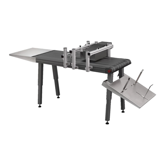
2 T3 OPX physical overview This is example 2.1 Front side Touch Screen Edge Sensor Bracket Vacuum unit (optional) Media Guides Catch tray Feeder table (optional) Table Adjustable emergency stop legs T3-OPX installation Page | 15... -
Page 17: Backside
2.2 Backside Height controllers (3) Serial plate Inlets Ink lid T3-OPX installation Page | 16... -
Page 18: Inlets Detail
Network (ethernet) IO serial port (fx for feeder) USB port Encoder serial port Table communication port 2.4 Bottom Pressure plate, area Crash plate. Protects that is used to detect the print head. the media height T3-OPX installation Page | 17... -
Page 19: Media Entry Side (Feeder Side)
Edge sensor reflective light emitter Knobs to move sensor 2.6 Media exit side Top lid. Access to electronic components Aerosol filter. Replaceable filter Front plate. Removeable to access print head area T3-OPX installation Page | 18... - Page 20 T3-OPX installation Page | 19...
-
Page 21: Installing The T3 Opx
3 Installing the T3 OPX This chapter describes how to install the T3-OPX using the standard bracket and height control actuators on a one of the two TrojanLabel conveyor tables (MT1 or MT2). The operation of the mailtables are identical, only the dimensions of the conveyor tables separates them. -
Page 22: Pre-Requisites
This step requires heavy lifting, ensure lifting equipment or extra personal is present to move the table (Check local rules and regulations). See chapter 1.5.5 or 1.5.6 for weight specifications. 1. Place the table upside down a. Place it on a mat or similar to protect the belts T3-OPX installation Page | 21... -
Page 23: T3 Opx Bracket System Installation Process
3.4 T3 OPX Bracket system installation process 1. Mount side brackets on both table sides. a. Use 2x2 slot knots that are in the middle, leave at least one pair (up and down) on each side of the side brackets T3-OPX installation Page | 22... - Page 24 Centre the brackets 400mm from the emergency stop button plate 400mm 2. Mount bracket system on the conveyor table a. Install the 4 corner posts loosely i. Do not tighten too much, as they will need to be adjust to the top bracket T3-OPX installation Page | 23...
- Page 25 Examples of raising the OPX unit, but this can also be a box (that can carry 20 kg) 4. Remove the OPX lid 5. Mount the screen a. Fit the screen on the bracket using the 4 screws b. Fit the cables on the PC (power, LVDS, mouse and ground) T3-OPX installation Page | 24...
- Page 26 6. Mount the actuators on the T3 OPX unit a. Push each actuator into place in the corresponding black plastic holder (closest to where the actuator cable enters the unit). T3-OPX installation Page | 25...
- Page 27 Notice the rotation of the actuator. The “motor” should be facing inwards and the hole at the bottom of the actuator, should line up with the black plastic mount c. Secure the actuator by pushing in the pin and secure it with the Pin on the end T3-OPX installation Page | 26...
- Page 28 This is normal and a part of the safety system. e. Carefully remove the padding under the T3 OPX print unit, ensure that the printer doesn’t drop hard. 8. Connect the actuator cables. a. It is important that they are connected as below: T3-OPX installation Page | 27...
-
Page 29: Connect Encoder And Table Controls (Trojan Mt1 And Mt2)
9. Mount the lid on the OPX 3.5 Connect encoder and table controls (Trojan MT1 and MT2) Prerequisites: 2 x serial cables included with the table 1. Connect the encoder serial cable 2. Connect the table communication cable T3-OPX installation Page | 28... -
Page 30: Remove Service Tray Plastic Protection
Remove the orange plastic protection, that ensures the service tray do not shift position during transportation. 1. Open the service door 2. Remove the two plastic parts 3.7 Connect T3-OPX power supply cord and network cables Prerequisites: 1 x power supply cord (with grounding) 1 x network cable Grounding: Always use the supplied power supply cord connected to a grounded power outlet. -
Page 31: Powering On
3.9.2 Power on process Turn on the power via the power inlet switch on both T3-OPX and mail table (MT1/2) 3.10 Calibrate the table position and level unit Calibrate the table position for the unit to determine the zero height position of the table and also ensure the unit is aligned to the table (x/y tilt). -
Page 32: Installing Ink Cartridges
Once all is in place, the unit is set in a special purge mode, which will require the operator to restart the unit (full power cycle). T3-OPX installation Page | 31... - Page 33 PSU. Purge will automatically start on next power on. a. If the unit failed to move to the print height, check if the height control has been initialized in the handling menu T3-OPX installation Page | 32...
- Page 34 The process will use the “purge height” in the settings menu T3-OPX installation Page | 33...
-
Page 35: Calibrate The Print Head Optional
Media entry sensor is calibrated to the high grade paper • 3.13.1 Nozzle alignment 1. Goto Diagnostics menu 2. Press ”Print Nozzle Alignment Plot” 3. Place the paper on the table 4. Press ”Print Nozzle Alignment chart” T3-OPX installation Page | 34... - Page 36 5. Press Scan the nozzle alignment chart 6. Set Die-to-die overlap to 0 a. This feature is explained in chapter 9 “Printing on uneven surfaces (die-to-die overlap feature)”. 7. Press ”Scan nozzle alignment chart 8. If successful, then apply the settings. T3-OPX installation Page | 35...
-
Page 37: Color Density
Scan the result b. If successful, then apply the settings. 5. Place the paper on the table 6. Press ”Print Nozzle health plot - EVEN” a. Scan the result b. If successful, then apply the settings. T3-OPX installation Page | 36... -
Page 38: General Settings (Home Tab)
4 General Settings (HOME tab) 4.1 Overview menu Information from currently printed job, including: • Preview image of the label which is being printed at the moment Label counter Name of print job in job library T3-OPX installation Page | 37... -
Page 39: Settings Menu
4.2 Settings menu • Service ID: A unique ID for each T3-OPX press. Based on the service ID, Trojanlabel support team can access to the Trojan Control via the internet from remote and provide technical support. • Actual software version: Version number of the Trojan Control interface (GUI) currently running on the machine. -
Page 40: Network Button
IMPORTANT: Press the blue ‘Save’ button to apply the changes. 4.2.2 Network Button Select ‘Use DHCP’ checkbox to acquire IP address for the T3-OPX from the local network (as long • as DHCP mode is selected, the T3-OPX ignores any static IP settings). -
Page 41: Updater Button
Press green ‘Download’ button to download updates if available (each time when a new update • is available a newsletter is released by Trojanlabel). Every time when change a setting use the blue ‘Save’ button to save the changes. •... -
Page 42: User Management Button
• 4.2.5 User Management button • By default user management is not enabled, therefore every function of the T3-OPX is accessible without user authentication. • Enable user management checkbox: When selected and activated, then user authentication is required for accessing specific functions in TrojanControl software. A user with ‘User Management’... -
Page 43: Printing Prefrences Button
WARNING: Do not lock out yourself! At least one user must have ‘User Management’ right otherwise there is no way to add or change properties of other users. In case you end up locked out please contact Trojanlabel support who can restore the default user settings. 4.2.6... -
Page 44: Statistics Menu
HOME -> Settings -> Consumables menu and in addition media price given at T3-OPX tab- > Media settings menu Job ID/Name is the name of the actual print job in the job library (unique name can be specified •... -
Page 45: Engine & Printhead Usage Button
• Print head: Total statistics and history for all the print heads which have been inserted into the T3-OPX. All print unit serial numbers will be registered and statistics for each printhead can be compared. NOTE: A printhead must print at least 1 page to be able to register the usage statistics. A freshly installed printhead that has not printed any pages is displayed as an empty record. -
Page 46: Shutdown
4.4 Shutdown Shuts down the T3-OPX completely. • NOTE: When shutting down the unit it is advised to wait with turning the power switch off until the shutdown process is finished. There is a message on the display when the shutdown process is initiated to indicate that the shutdown process is still going on. -
Page 47: Exporting Statistics Data To A Csv File/ Viewing Statistics From A Browser
T3-OPX. • Actual IP address of the T3-OPX can be set or acquired at/from HOME -> Settings -> Network menu Current IP address displayed at HOME -> Settings -> Network menu NOTE: IP address on screenshot above is an example only. - Page 48 Closer view NOTE: Ink consumption is more detailed in this view and displayed for each used base color (CMYK) and in total as well. T3-OPX installation Page | 47...
-
Page 49: Transferring Print Jobs To The T3-Opx Using The Xitron Rip
5 Transferring print jobs to the T3-OPX using the Xitron RIP This chapter will walk throuh the steps on how to transfer a job to the job library of the T3-OPX using the Xitron RIP. 5.1 Starting the Xitron RIP Server To transfer jobs using the Xitron RIP it is required that the RIP server is running. - Page 50 5. In the Full Job Editor screen you can do the same changes as the QUICK JOB EDITOR as well as changing the Paper Profile, Overall Color Changes and Spot Color Adjustments. When you have T3-OPX installation Page | 49...
-
Page 51: Print Direction
"Print" and your file will be sent to the printer. 6. Press Print to send the job to job library on the T3-OPX 5.2.1 Print direction The print direction is “up”, and the top edge will be printed first: 5.2.2... - Page 52 Rotation is done using the ”rotation”-button. Below is an example of the pizza artwork being rotated. If settings are set to original will rotation be possible without having to modify the media size. Offset buttons T3-OPX installation Page | 51...
- Page 53 3. Click on the image to activate the anchor points 4. Click the top right to place it. a. Note: if the standard Media Sizes are not fit for the artwork, then create a custom media size (see chapter 5.2.2.3 Creating custom media sizes) T3-OPX installation Page | 52...
- Page 54 5. Set the width and height 6. Click + button and give the Media size a new name. 7. Open the DFE in browser again 8. Select the new Media in the size drop down. T3-OPX installation Page | 53...
-
Page 55: Printing A Job From The Job Library
3. Go to the job library 4. Select the print job (indicated by a red square) 5. Enter the number of units to print, by clicking the units button Start Print Selected job Units button T3-OPX installation Page | 54... -
Page 56: Operations Menu
This chapter will explain how to create and manage media profiles. 7.1 Handling overview The ”Handling” menu is used for moving the print unit up or down, moving the mail table and adjusting/testing the vacuum fans when printing. T3-OPX installation Page | 55... -
Page 57: Initialize Height Control
Use the Zone (1-5) controls to individually set the fan speed from 0 to 100. 7.1.3.3 Emergency stop The emergency stop placement: T3-OPX installation Page | 56... -
Page 58: Maintenance Overview
The emergency stop can be released by twisting the emergency stop button. 7.2 Maintenance overview The maintenance menu controls the print head maintenance functions, which includes cleaning, replacinf the service tray, testing print position and print head capping T3-OPX installation Page | 57... -
Page 59: Light Clean
The print head will be uncapped for 60 seconds and the automatically cap again. IMPORTANT: only use a clean lint free cloth and DI water. Wipe gently across the surface. T3-OPX installation Page | 58... -
Page 60: Cap Print Head
Save properties to a new media profile. Type in the name of the new profle and press the small save button. Important: It only saves the profile, they are not applied, until the apply button is saved T3-OPX installation Page | 59... -
Page 61: Basic Tab
Moves the media placed on the conveyor belts on the entry side under the pressure plate, then starts the automatic heigh adjustment. When complete will the media be moved back to the starting position. Requirement: The entry sensor must be able to register the media. T3-OPX installation Page | 60... -
Page 62: Advanced Tab
Set the directional tilt in millimeters (+/- 5mm). Mid Job maint. Distance. • Set the number of units that the system will print, before stopping and performing ”mid job maintenance”. The counter is reset after each job. T3-OPX installation Page | 61... -
Page 63: Fans Tab
TOF (Top of form, i.e the distance from the leading edge of the media). T3-OPX installation Page | 62... -
Page 64: Automatically Calibrating The Job/Media Height
8 Automatically calibrating the job/media height The T3-OPX can automatically adjust the height controllers to the media that the operator wants to print on. The height can then be saved to media profile. Please refer to 7.1 ”Handling overview” and 7.3 ”Media settings overview”... - Page 65 2. Setting the force too high can crush the material. 3. If t he edge sensor does not detect the material, then the belt will stop and return the media and display an error ”Auto print height adjust error: product not found” T3-OPX installation Page | 64...
-
Page 66: Printing On Uneven Surfaces (Die-To-Die Overlap Feature)
It is recommended to set the print height in the media settings first, to ensure consistency in the process: Process of adjusting the die-to-die overlap: 1. Go to T3-OPX tab -> Diagnostics 2. Select “Scan Nozzle alignment plot” 3. Insert the die-to-die overlap value (-8 to 7) 4. -
Page 67: Edge Sensor (Tof Control)
DO NOT place the sensor over a belt, as this will interfere with the edge registrations. Sensor controller Edge sensor reflective light emitter Knobs to move sensor T3-OPX installation Page | 66... -
Page 68: Sensor Overview
High Yield Black Ink Cartridge (~20,000 pages) 11.2 Service tray replacement When the end of Service tray life has been reached, which is indicated by the Service tray life in the status menu display “0%”, replace the service tray: T3-OPX installation Page | 67... -
Page 69: Service Tray Replacement Process
11.2.1 Service tray replacement process 1. Unpack the new service tray 2. Ensure the unit is not printing. 3. Go to the “T3-OPX” tab 4. Select Maintenance 5. Press “Remove Service Tray” 6. Open the “service door” on the feeding side of the unit, by removing the four finger screws... - Page 70 It can carry the weight of the optional Vacuum unit 8. Wait for the service tray to be pushed to the end 9. Pull the service tray out 10. Install the service tray, by pressing it back into position.Press install Service Tray T3-OPX installation Page | 69...
-
Page 71: Moving The Service Tray Manually
The fuse in the power inlet can be replaced by the operator Part number Description 15140120 FUSE T3.15A 11.3.1 Fuse replacement process Remove power cord cable before continuing 1. Open the fuse lid on the power inlet carefully using a flat head screw driver. T3-OPX installation Page | 70... -
Page 72: Aerosol Filter
The filter can be replaced during printing, but this is not recommended. Part number Description 27760660 T3-OPX AEROSOL FILTER The aerosol filter is placed on the media exit side. Aerosol filter drawer. Replaceable filter T3-OPX installation... -
Page 73: Aerosol Filter Replacement Process
11.4.1 Aerosol filter replacement process 1. Remove the aerosol filter drawer, by pulling the handle 2. Remove the filter in the drawer 3. Insert a fresh filter 4. Insert the aerosol filter drawer T3-OPX installation Page | 72... -
Page 74: Rip Installation (Xitron)
Type in the 36 digit code c. It is recommended to use the default directories when prompted for location d. Type in the ip address of the T3-OPX when prompted for it. i. To find the ip address, see chapter 4.2 Settings menu 4. -
Page 75: Installing Just The Client
Insert the IP address of the RIP server 12.2 Installing just the client To install just a client on a PC in the same network as the RIP server and printer, run the following file: 1. NavigatorHHRClientInstaller.exe T3-OPX installation Page | 74... -
Page 76: Debugging Connections
1. To debug the webpath board Connect an external PC to the T1030 board (the new webpath) a. Use a USB -> USB Mini to connect 2. To the MPCA to a an external PC to the MPCA a. Use a USB AB to connect T3-OPX installation Page | 75... -
Page 77: Controls For T1030 (Webpath Board)
0 power is provided 1 power is cut Lgram <1,2,3 or 4> Read the weight on of the individual load sensor, there are 4 in total Lgramt Read the total weight on the No parameters load sensors T3-OPX installation Page | 76... -
Page 78: Revision History
14 Revision history Thomas Jensen Thomas Jensen Add RIP ip address (12.1) and die-to-die overlap feature (9) Thomas Jensen RIP Rotation and offsetting explained. Manual service tray movement T3-OPX installation Page | 77...
Need help?
Do you have a question about the T3-OPX and is the answer not in the manual?
Questions and answers