Table of Contents
Advertisement
Quick Links
Advertisement
Table of Contents

Related Manuals for Gravotech Laser Workstation LW2 Touch

Summary of Contents for Gravotech Laser Workstation LW2 Touch
- Page 1 OPERATING AND MAINTENANCE MANUAL Laser Workstation LW2 Touch MARKING LASER...
-
Page 2: Table Of Contents
Table of contents A. Foreword ..............................6 1. Appreciation ............................6 2. Information ............................6 B. Legal notices ............................7 C. Regulation observance ...........................8 D. Required safety labels ..........................9 E. Introduction ............................11 1. Presentation ............................11 2. Instructions for use and warranty limitations ..................11 3. Identification of the marking equipment .................... - Page 3 Color touch screen ..........................22 1. Main screen ............................23 „ Main menu ............................23 „ Start marking ............................. 23 „ Stop marking ............................23 „ Door opening/closing ......................... 24 „ Z axis ..............................24 „ Door opening/closing: Automatic mode ..................... 25 2. Marking parameters ..........................26 „...
- Page 4 K. Connections - Installation ........................53 1. Connecting the Control Unit (Fiber series (+ Energy)) ................. 53 2. Installation ............................58 „ Possible integration and operating positions for the Fiber Series (+Energy) ........58 „ Possible integration and operating positions for the Hybrid - Green - CO2 Energy Series ....58 „...
- Page 5 P. Technical specifications ........................71 1. Physical characteristics ........................71 2. Electrical characteristics ........................72 3. Environment ............................72 4. Laser beam ............................72 5. Aiming diode - Focusing diode ......................72 6. Material ..............................73 M_LW2 Touch_EN_B...
-
Page 6: Foreword
A. Foreword 1. Appreciation Thank you for choosing LW2 Touch - Gravotech. Gravotech is pleased to count you among the users of its engraving and traceability solutions. For help, contact Gravotech. For more information on products, visit www.gravotech.com website. 2. Information To ensure security and productivity, read this manual before starting-up the equipment. -
Page 7: Legal Notices
User. Gravotech shall not be liable for any damages, that the User or its property, a third party or the Product itself may suffer, caused by the Product and arising from any inappropriate use or misuse of the Product, negligence, carelessness, inadequate supervision or maintenance, failure to observe the safety or usage instructions described herein or otherwise communicated to the User, the use of poor- quality or non-recommended lubricants, fluids and additives or where there is fault on the part of the User or a third party. As provided in... -
Page 8: Regulation Observance
C. Regulation observance Last updated: 01/2020 EC declaration of conformity or declaration of incorporation supplied with the machinery Type of machine Directives - Standards Dot peen marking: Machine - Low voltage: 2014/35/EU XF500p, XF500m, Impact p, Impact eZ p, Impact m, Impact eZ m - EMC: 2014/30/EU P5000PN, P5000EM - RoHS 2: 2011/65/EU... -
Page 9: Required Safety Labels
D. Required safety labels Last updated: 01/2020 Required safety labels Machines concerned Shared labels Warning: Warning: Crushing Refer to instructions Warning: Laser beam General warning Flammable Warning: Electricity of hands manual/booklet. materials LS100 LS100 Ex LS100 Energy "Passthrough" function LS900 LS100 LS100 Ex Fibre LS900 Edge LS900 XP LS100 Ex... - Page 10 Required safety labels Required safety labels Machines concerned Shared labels Refer to instructions Warning: Laser beam General warning Warning: Electricity manual/booklet. Laser Solution Hybrid-Green-CO2 Laser Solution Laser Solution Laser Solution Laser Solution Series (standard Hybrid Series Green Series CO2 Series Fiber-Series version, version (standard version, (standard version, (standard version,...
-
Page 11: Introduction
(period or number of cycles) is reached. 3. Identification of the marking equipment The marking equipment is identified by: • 1 identification plate on the rear face Have the model and serial number of the equipment available when contacting Gravotech. „ Description of symbols used (ID plate) Alternating current Fuse The equipment must be disposed of at an appropriate collection point for Logo meets "EC"... -
Page 12: Work Station Safety
In the event of an extended period of non-use, unplug the power cable and protect the machine. • Never pour or spill liquid on the machine (drinks, cleaning products, etc.) except where recommended by Gravotech. Gravotech will not be held responsible for injuries resulting from disregard for the above operating instructions or other general safety rules applicable to the use of this equipment or resulting from misuse. Furthermore, disregard for the instructions will void the warranty. M_LW2 Touch_EN_B... -
Page 13: Unpacking
F. Unpacking 1. Packaging Protective foam Wedge Contents of the box: screen + mounting bracket + cables Protective foam LW2 Touch (maximum: 60 kg (132.277 lb)) Wedge Pallet M_LW2 Touch_EN_B... - Page 14 Unpacking Unpack the machine with 3 operators. LW2 Touch (weight: 60 kg (132.277 lb)) Unpack the machine with 3 operators. Handles (x 6) M_LW2 Touch_EN_B...
-
Page 15: Laser Safety
(non-exhaustive list). Only trained personnel aware of the risks posed by the machine are authorized to use it. Only Gravotech personnel, or persons authorized by Gravotech may service the elements that constitute the marking machine. -
Page 16: Labels
Laser safety 2. Labels „ Warranty labels These labels guarantee the laser was not opened or dismantled. Opening without prior written consent voids warranty. DO NOT OPEN LASER COVER WARRANTY VOID IF SEAL IS BROKEN * * DO NOT OPEN THE LASER COVER WARRANTY VOID IF SEAL IS BROKEN „... -
Page 17: Work Station Safety
Laser safety 3. Work station safety Specific hygiene and safety instructions Personnel laser radiation protection Concerned industrial use installation: Use: Installation: Restricted area The room in which this sign is posted is defined as a restricted laser area: • in normal production phase (1) • maintenance and setting phase (1) • ................(1) Regulation in the restricted area Access to the restricted laser area is regulated. Only competent personnel having attended proper training can remain during the operation: this implies medical aptitude and laser safety training. -
Page 18: X84; General Instructions
Laser safety „ General Instructions • Avoid any exposure to laser radiation. • Do not put hands or an object in the laser beam's trajectory. • Never stare into the primary laser beam. • Avoid direct eye exposure to diode laser beam. •... -
Page 19: Potential Hazards Related To Materials Worked With
Laser safety 4. Potential hazards related to materials worked with „ Fumes and toxic particles Laser marking certain materials emits dangerous fumes and particles that may be toxic and/or damage the equipment. In this case, adapt an extraction system (with filtration if necessary) to the marking station. -
Page 20: X84; Examples Of Secondary Radiation Risks
Laser safety „ Examples of secondary radiation risks The use of a class 4 laser device can generate: • A risk of fire or explosion due to materials or inflammable substances • UV radiation • X rays • High intensity visible light when marking on certain materials „ Reflected beam Special integration is required when marking some materials to prevent the beam reflecting. • Copper, copper-based materials (bronze, brass) • Gold • Silver • Polished materials M_LW2 Touch_EN_B... -
Page 21: Description Of The Machine
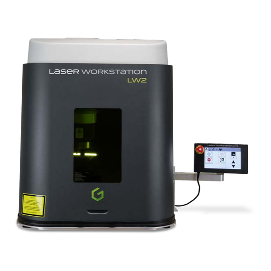
H. Description of the machine „ Global view of the marking area Door Laser protection glass Motorized Z-axis Mount: marking head Marking area lighting Color touch screen Support feet M_LW2 Touch_EN_B... -
Page 22: Color Touch Screen
I. Color touch screen Piloting via an internal program The window appears when the tablet is started up. To confirm, press the key: Confirm and move. The laser is reset. The door moves to its origin. Axis origin set: Press. (press and hold - 3 s). M_LW2 Touch_EN_B... -
Page 23: Main Screen
Color touch screen 1. Main screen Main menu Start marking Stop marking Door opening/closing CCU information Z-axis raising / Z-axis lowering Edit: head positioning: Z Date/Time Absolute distance / Reference value 10. Door opening/closing: Automatic mode „ Main menu Icon used to return to the main menu, followed by the name of the menu. This icon appears several times in the program. -
Page 24: X84; Door Opening/Closing
Color touch screen „ Door opening/closing When not in automatic mode, pressing once on the button causes the door to change status. Do not hold the button down. In automatic mode, the button is disabled. „ Z axis The motorized Z axis is controlled via the touch screen. Display of the position of the Z axis in relation to absolute 0. -
Page 25: X84; Door Opening/Closing: Automatic Mode
Color touch screen „ Door opening/closing: Automatic mode Click on: The screen below appears: Indicator lights on Automatic mode must be activated when the door is open. Marking time must exceed 1 second. The indicator light signals whether automatic mode is activated. When marking is started, the door closes, marking is executed and the door opens at the end of the cycle. Automatic mode is compatible with marking management modes (independent, infinite, N times, etc.) It is essential to start marking with the touch screen. It is no longer possible to use the raise and lower buttons. It is no longer possible to modify the position of the Z axis. -
Page 26: Marking Parameters
Color touch screen 2. Marking parameters „ Configuration: Command Marking parameters Command Network configuration Adjustment System information Update / Backup/restore data "Safety circuit reset" button Activation/deactivation of the extractor Marking area lighting (On/Off) • Safety circuit reset Switching on the laser source following start-up or an emergency stoppage of the machine. Fume extraction - filtration •... -
Page 27: X84; Network Configuration
Color touch screen „ Network configuration Allows the machine's network connection to be set up. The screen below appears: Network configuration DHCP mode Port number "Check" key Gateway Subnet mask IP address When DHCP mode is selected, an IP address and a subnet mask are automatically assigned. M_LW2 Touch_EN_B... -
Page 28: X84; Adjustment
Color touch screen „ Adjustment Activate screen calibration Adjustment Date "Check" key Time Brightness Activation of the buzzer Units (mm or inches) „ System information This menu contains technical information that can be communicated to the distributor or the technical support in case of problem. -
Page 29: X84; Update
Color touch screen „ Update Insert the USB key into the LW2 Touch. File imports and updates are performed via USB key. Selecting the update file Select the file. M_LW2 Touch_EN_B... - Page 30 Color touch screen To confirm, press the key: • Backup: Memory backup Used to backup all the data to a single file. Press the key: Backup M_LW2 Touch_EN_B...
- Page 31 Color touch screen The file created in this way may be saved to a USB key but may not be opened. • Restore: Data recovery Used to restore all the data previously backed up. Press the key: Restore Select the file. M_LW2 Touch_EN_B...
-
Page 32: File" Menu
Color touch screen 3. "File" menu „ Marking file "File" menu Marking file Logos Fonts USB connection Loading the marking files File simulation Delete „ Logos List of available logos (in the marking file(s)): M_LW2 Touch_EN_B... -
Page 33: X84; Fonts
Color touch screen „ Fonts List of available fonts (in the marking file(s)): „ USB connection Connect the USB key to the machine. File imports and updates are performed via USB key. List of marking files: M_LW2 Touch_EN_B... -
Page 34: Variables" Menu
Color touch screen 4. "Variables" menu Allows the user to modify the content of the variables in the marking files. The PC can be disconnected. 5. Menu: Security mode „ "Supervisor" mode This mode is selected by default. Used to limit access to certain functions in the program. Switching from one operating mode to another is password protected. - Page 35 Color touch screen Setting the password: click on: Change password. M_LW2 Touch_EN_B...
-
Page 36: X84; "Operator" Mode
Color touch screen „ "Operator" mode Select either "Supervisor" or "Operator" mode for the operating mode of the program. Functions accessible in "Operator" mode: • Main menu: - Start marking - Stop marking - Door opening/closing - Door opening/closing (Automatic mode) - CCU information - Absolute distance / Reference value - Z-axis raising / Z-axis lowering - Edit: Head positioning: Z... - Page 37 Color touch screen • Marking parameters Command System information Saving parameters "Safety circuit reset" button Activation/deactivation of the extractor Marking area lighting (On/Off) M_LW2 Touch_EN_B...
- Page 38 Color touch screen • "File" menu Loading the marking files File simulation The operator cannot delete the files. System information: M_LW2 Touch_EN_B...
-
Page 39: X84; Technician Mode
Color touch screen • "Variables" menu - Set variable „ Technician mode This option is password protected. Configuration - Firmware: only an approved technician is authorised to carry out this operation. Technician mode Program management Menu: Diagnosis Menu: Inputs / Outputs M_LW2 Touch_EN_B... -
Page 40: Emergency Stop
Color touch screen 6. Emergency stop Pull on the emergency stop button in order to deactivate it. Follow the instructions on the screen. Click on "OK". • Safety circuit reset: Click on the icon: Click on the icon: M_LW2 Touch_EN_B... - Page 41 Color touch screen • Fault acknowledgement: click on the icon: • Return to origin: click on the icon: (press and hold: 3 s). The head goes back to the origin. To go back to the main menu or to the last screen, press the corresponding icon: The machine is ready for operation. M_LW2 Touch_EN_B...
-
Page 42: Installation
J. Installation 1. Electrical installation Turn off the machine before beginning any cleaning, maintenance or repair procedure. Always switch the machine off before connecting or disconnecting a cable or optional accessory. Never unplug a cable while the machine is turned on (except for the mains lead in the event of an emergency). The power outlet must be located alongside the equipment and must be easily accessible. Do not remove the power supply cover: risk of electric shock. - Page 43 Installation 2. Tilt the cover forward slightly. 3. Raise the cover by approximately 10 mm (0.394 in) by pulling it towards the rear in order to free up space at the front, between the cover and the door. 4. Tilt the cover until vertical. 5.
-
Page 44: X84; Step 2
Installation „ Step 2 Remove 2 screws CHC M5x45 in order to release the counterweights. Retain the screws for any future shipping operation (maintenance, after-sale service, etc.) 3. Fiber series (+ Energy) „ Step 3 1. Remove the screws (x4). M_LW2 Touch_EN_B... - Page 45 Installation 2. Open the flange at the back. If there is already a laser in the machine: 1. Remove the screws (x4): 2. Open the flange at the back. M_LW2 Touch_EN_B...
-
Page 46: X84; Step 4
Installation „ Step 4 1. Place the laser in the LW2 Touch, on its support (Z axis). 2. Use the screws provided to attach the marking head to the frame designed for this purpose. Do not touch the other screws in the marking head. -
Page 47: X84; Step 5: Optical Head Connection
Installation „ Step 5: Optical head connection Never hold or manipulate the optical head by the fiber. Always use the aluminium isolator mount to manipulate. 1. Insert the optical head in the marking head and fasten with the 3 M5 screws supplied (3D lens: Mount with the 2 screws). 2. Mount the 2 flanges using the 6 M5 screws provided. -
Page 48: X84; Step 6: Connection Of The Marking Head To The Ccu
Installation „ Step 6: Connection of the marking head to the CCU Do not touch the other screws in the optical head. See below. Marking head - View of connectors 17 point connector - Head/CCU connecting cable 19 point connector - Head/CCU connecting cable Optical head 1. Connect the 17 point connector. 2. Connect the 19 point connector. Do not touch the optical head. - Page 49 Installation Fit the protection caps (supplied with the machine). Protection cap(s) No light must be allowed to pass between the flange, the laser and the cables. 4. Re-close and lock the upper flange. If closing the flange is difficult, unplug the laser connectors or tighten the flanges using locking pliers, protecting the bellows (thick plastic or cardboard). 5. Close the housing (reverse of the disassembly operation).
-
Page 50: Hybrid - Green - Co2 Energy Series
Installation 4. Hybrid - Green - CO2 Energy series „ Step 3 1. Remove the screws (x4). Open the flange at the back. Remove the laser, if present. Remove the closing plate at the back of the machine to install the Laser module. M_LW2 Touch_EN_B... -
Page 51: X84; Step 4
Installation „ Step 4 1. Place the laser in the LW2 Touch, on its support (Z axis). 2. Reclose and lock the flange. No light must be allowed to pass between the flange, the laser and the cables. 3. Use the screws provided to attach the marking head to the frame designed for this purpose. Do not touch the other screws in the marking head. - Page 52 Installation 4. Close the housing (reverse of the disassembly operation). M_LW2 Touch_EN_B...
-
Page 53: Connections - Installation
K. Connections - Installation 1. Connecting the Control Unit (Fiber series (+ Energy)) The different elements of the equipment must be connected with the power off. The power supply should be connected last. Control Unit - LW2 Touch: View of connectors 19 point connector Head/CCU connecting cable (cable supplied): Marking-head signals 17 point connector Head/CCU connecting cable (cable supplied): X-Y signals Profinet/Ethernet IP module (optional) 7 point connector (DIN F) - Not available 3 point connector (DIN F) - Not available DB15F connector... - Page 54 Connections - Installation • Connection of the marking head to the CCU 1. Connect the marking head to the CCU with the two connection cables provided (17 points - 19 points). 2. Push the connectors into the socket and tighten the locking rings. 3.
- Page 55 Connections - Installation • Connection: Tablet • Connection RD1/RD2 (optional) Cable + flange kit LW2 Touch Control Unit M_LW2 Touch_EN_B...
- Page 56 Connections - Installation • Fume extractor connection: ES30 (optional) 1. The different elements of the equipment must be connected with the power off. The power supply should be connected last. 2. Remove the cover. 3. Attach the exhaust tube adapter. 4. Connect tube Touch (diameter 100). Tighten the hose clamp. 5.
- Page 57 Connections - Installation 6. Connect the cable ES30 / LW2 Touch. • Power supply connection LW2 Touch Control Unit M_LW2 Touch_EN_B...
-
Page 58: Installation
Connections - Installation 2. Installation „ Possible integration and operating positions for the Fiber Series (+Energy) Position the Control Unit horizontally, in a dry, ventilated area, at least 20 cm (7.874 in) from the floor. Always leave a free space of 50 mm (1.969 in) in front of the CCU and of 150 mm (5.906 in) in back for good air circulation. As components are air-cooled, air circulation in the CCU must not be perturbed. Version rack 19" 4U-5U: used to integrate the CCU in a cabinet. Vertical position possible Analyse the CCU's integration in order to avoid problems due to the fiber's minimum bend radius. -
Page 59: X84; Laser Startup
Connections - Installation „ Laser startup See the user manual of the machine. The shutter closes automatically when the door opens and it opens automatically when the door closes. The marking can only be carried out if the door is closed. When the machine is working in Class 1 - 2M protective goggles are not obligatory. -
Page 60: Accessories Available Upon Request
L. Accessories available upon request Please give the item codes with your order to speed processing. 1. List of accessories and options available upon request Reference Description 77650 (Hybrid Energy 3D module Series) 78636 (Fiber Series Built-in system mounted in factory (+Energy)) Used to mark at different distances without the need to refocus. - +/- 30 mm (1.181 in) (F160) - +/- 60 mm (2.362 in) (F254) 78272 (Hybrid - Green - Autofocus... -
Page 61: X84; Rotary Device
Accessories available upon request „ Rotary device Reference Description 79251 - Marking small to medium diameter cylinders - Key chuck Diameter: 3 mm (0.118 in) - 98 mm (3.858 in) For more information, consult the manual of the machine in question. 79252 - Marking small to large diameter cylinders - Key chuck Diameter: 3 mm (0.118 in) - 152 mm (5.984 in) For more information, consult the manual of the machine in question. -
Page 62: X84; Other Accessories
Accessories available upon request Reference Description ES10: Fume extractor for small applications, in the case of occasional marking (marking on plastic) Connecting cable(s): Laser fume extractor (ES10) / Hybrid- Green - CO2 - Fiber Series (+ Energy) 60995 - 230 V (UE) 60996 - 230 V (UK) 60997 - 230 V (CH) 60998... -
Page 63: Wearing And Spare Parts
Accessories available upon request 2. Wearing and spare parts „ Spare parts Reference Description 81949 Color touch screen Kit: support feet 54260 CCU/LW2 Touch connection cable (37 point connector) „ Wearing parts Reference Description 66539 Door seal 69908 Microswitch kit (1 microswitch + fastenings) M_LW2 Touch_EN_B... -
Page 64: Preventive Maintenance
M. Preventive maintenance 1. Visual inspection of the bellows (rear of LW2 Touch) Upper bellows Lower bellows Check the condition of the bellows in the event of burning or perforation. M_LW2 Touch_EN_B... -
Page 65: Every Year
Preventive maintenance 2. Every year (Or in the event of noise emanating from the Z axis screw) 1. Raise the bellows. 2. Re-lubricate the Z axis screw using the grease pack supplied. „ Cleaning the sensors The Z axis is equipped with a sensor to detect the end of travel along Z. This optoelectronic fork sensor indicates the presence of the 2 carriages at the origin. Certain exterior elements (chips, shavings...) can get stuck between the sensors and disrupt their functioning. To remove these foreign objects, use an air gun to direct a shot of air between the sensor. M_LW2 Touch_EN_B... -
Page 66: Dimensional Drawings
N. Dimensional drawings 1. LW2 Touch dimensional drawing 11 12 13 4 support feet (adjustable) Laser protection glass: 180 mm (7.087 in) x 280 mm (11.024 in) Color touch screen Mount (color touch screen) Cover M6 packing bolts (x4) Door Control interface board Mobile protective shutters 10. -
Page 67: Fiber - Hybrid - Green - Co2 Energy Series
Dimensional drawings 2. Fiber - Hybrid - Green - CO2 Energy Series „ LW2 Touch dimensional drawing Optical fiber axis Z axis (Travel distance 295 mm (11.614 in)) Marking area: 100/160/254/330 Focal lens Weight: 69 kg (152.119 lb) (LW2 touch + Fiber series (+ Energy) marking head) M_LW2 Touch_EN_B... -
Page 68: X84; Dimensional Drawing Of The Table
Dimensional drawings „ Dimensional drawing of the table Marking area: 205 mm (8.071 in) x 205 mm (8.071 in) Marking area: 175 mm (6.890 in) x 175 mm (6.890 in) Marking area: 110 mm (4.331 in) x 110 mm (4.331 in) Handles (x4) Marking area: 65 mm (2.559 in) x 65 mm (2.559 in) 27 fastening holes (M6) Origin M_LW2 Touch_EN_B... -
Page 69: Max Height Of The Part To Be Marked
Dimensional drawings 3. Max height of the part to be marked „ 100 Focal lens Fiber Series (+ Energy) Hybrid Energy Series Green Energy Series CO2 Energy Series 345 mm (13.583 in) „ 160 Focal lens Fiber Series (+ Energy) Hybrid Energy Series Green Energy Series CO2 Energy Series 160 Focal lens: 255 mm 160 Focal lens: 216 mm 165 Focal lens: 219 mm... -
Page 70: Noise Emission Of The Machine
O. Noise emission of the machine 1. Test code „ Measurement method The measurements were taken according to the regulations of standard ISO 12001:1996. „ Material used for marking: • Machine: LW2 Touch + Fiber Energy Series 20 W • One electronic command unit • An interface computer (used by the operator) „ Definition of the microphone position The microphone is positioned 1 m (3.281 ft) in front of the machine and 1.4 m (4.593 ft) from the floor. -
Page 71: Technical Specifications
P. Technical specifications 1. Physical characteristics Dimensions (L x w x h): Machine 600 mm (23.622 in) x 622 mm (24.488 in) x 772 mm (30.394 in) Dimensions (L x w x h): Laser 180 mm (7.087 in) x 280 mm (11.024 in) protection glass Net weight: Machine 60 kg (132.277 lb) (no accessories) Dimensions (L x D x H): With 778 mm (30.630 in) x 764 mm (30.079 in) x 985 mm (38.779 in) packaging Weight: With packaging 66 kg (145.505 lb) -
Page 72: Electrical Characteristics
Technical specifications 2. Electrical characteristics Nominal voltage 100 - 240 V AC Frequency 50 / 60 Hz Power 800 W Electrical protection by fuse 6.3 A --> Voltage: 115 V 3.15 A --> Voltage: 230 V Phases 3. Environment Operating temperature 15 °C (59 °F) - 35 °C (95 °F) Storage temperature 10 °C (50 °F) - 40 °C (104 °F) -
Page 73: Material
Technical specifications 6. Material Fiber Series Hybrid Energy Green Energy CO2 Energy (+ Energy) Series Series Series 20 - 30 - 50 W 10 - 20 W 20 - 30 W Metal support Steel, stainless steel Aluminium Carbide Copper, brass Titanium Gold, silver, nickel, platinum Plastic...
Need help?
Do you have a question about the Laser Workstation LW2 Touch and is the answer not in the manual?
Questions and answers