Table of Contents
Advertisement
Advertisement
Table of Contents

Related Manuals for Messersi SL 45

Summary of Contents for Messersi SL 45
- Page 2 - Denne manual følger med hver maskin. - Denne manual er lagd og formulert I hht EEC regulative og da spesielt til UNI-ISO 6750 regulativ. - Denne manual gir informasjon om broken av maskinen , og da spesielt i hht de sikkerhets prosedyrer en må...
- Page 3 PRESENTASJON AV MASKINEN Side 5 • MASKIN IDENTIFISERING. Side • HOVED DELER PÅ MASKINEN Side • KARAKTERISTIKKER , TEKNISKE DATA OG YTELSE Side • TRANSPORT OG HÅNDTERING Side • PRESCRIPTIONS FOR CIRCULATION ON ROADS Side GENERAL SAFETY REGULATIONS Side 13 •...
- Page 4 PRESENTATION OF THE MACHINE...
-
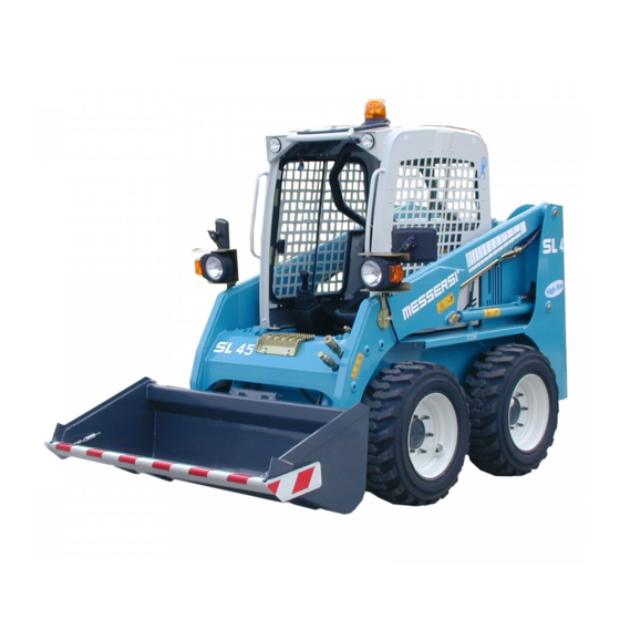
Page 5: Machine Identification
The loading shovel has been designed and built for loading and unloading earth, gravel, sand, debris and other loose material and is however suitable to operate in compliance with the features and performance indicated in this manual. It is a machine with Diesel internal combustion motorisation with hydrostatic transmission, joy-stick type servo-controls for traversing and manoeuvre of the arms and the bucket. -
Page 6: Characteristics And Technical Data
CHARACTERISTICS AND TECHNICAL DATA ENGINE Brand and model Kubota V 2203-E Calibration Power at 2600 rpm HP/Kw 44/32.5 Cylinders Nº Displacement 2197 Cooling water HYDRAULIC SYSTEM: Hydrostatic transmission with n.2 variable capacity pumps that each power, n. 2 fixed-cylinder hydrostatic motor reducers. Negative command brakes on the motor reducers of the rear axle wheels. -
Page 7: Overall Dimensions
OVERALL DIMENSIONS TRANSPORT AND HANDLING LOADING WITH RAMPS AND TRANSPORT BY TRUCK The machine loading and unloading operations must be carried out on a compact and level surface. Check that the transport vehicle is in perfect condition. Apply the hand brake and insert safety wedges at the front and rear of the rear axle tyres. - Page 8 Check that the ramps are properly coupled to the transport vehicle and appropriately spaced. The width of the ramp must be such as to allow comfortable passage of the tyres. The ascent and descent operations must always be carried out with the machine running and the hydraulic oil at operating temperature.
- Page 9 TRANSPORT Once the machine has been positioned on the loading platform, also rest the bucket on it lightly and block the machine in a longitudinal direction by inserting wedges to the outside of the front and rear axle tyres. For transversal and vertical blocking use belts to prevent lateral and vertical movement owing to jolts during transport.
- Page 10 PRESCRIPTIONS FOR CIRCULATION ON ROADS For correct road circulation comply to all specified below. 1 - Flashing lights. 2 - Shovel blocking pin in maximum lifting position 3 - Shovel sharp edge lateral and front protections. 4 - Plate positioning. PRESCRIPTIONS - Working system commands must be blocked.
- Page 11 GENERAL SAFETY REGULATIONS...
-
Page 12: General Regulations
WARNING AND SAFETY DECALCOMANIA AND PLATES The plates applied, other than indicating the various manoeuvres for machine control and use, serve to point out the risks connected with machine operation. An operator who wears glasses must use them to read the plates. Keep all the plates clean and legible paying particular attention to the safety warnings indicated. -
Page 13: Operating Safety
SAFETY REGULATIONS FOR STARTING The machine must only be driven by qualified staff that are at least 18 years old. Before getting on, inspect the machine. To enter or exit the cabin it is advisable to always turn towards the vehicle. Use the steps and the handles. -
Page 14: Rear Window
In case of EMERGENCY the operator can use n. 2 escape routes. These are the front opening and the rear window of the driver’s cabin. REAR WINDOW: To remove the glass pull the relative peg (ref. 1) positioned on the central part of the rubber seal and remove the insert it includes. - Page 15 MOVEMENT ON SLOPES Movement on slopes and craggy areas must be carried out with caution; a high risk exists for the operator and whoever is working in the area. To limit risks to a minimum follow the indications below. · The loaded shovel must always be upstream, both in ascent and in descent.
- Page 16 SAFETY REGULATIONS FOR STOPPING AND PARKING Never leave the machine with the engine running. After leaving the driver’s seat, and after ascertaining that there are no persons near the machine, slowly lower and rest the equipment on the ground. Set the controls in the rest position. If possible, park the machine in an area where no other machines are operating and where there is no vehicle traffic.
- Page 17 FIRE-EXPLOSION PREVENTION REGULATIONS Flames or sparks can cause the battery and fuel to explode and therefore set fire to the machine. To avoid and prevent the causes please follow the advice given below. Equip the machine with an extinguisher. After any use, reload or replace it. The extinguisher must always be in perfect working order.
- Page 18 OPERATOR CONTROLS DRIVER’S POSITION...
-
Page 19: Safety Belts
OPERATOR POSITION CORRECTLY SEATED IN THE DRIVER’S POSITION SEAT The driver’s seat must not be adjusted while the vehicle is moving. Danger of accidents! Always fasten the seatbelts. The driver’s seat is important for good health. Therefore it must be maintained integral. The driver’s seat can be adjusted longitudinally using the special lever positioned low on the right hand side. -
Page 20: Safety Bar
SAFETY BAR Every machine is equipped with a safety bar that together with the safety belts and cabin in compliance with ROPS and FOPS makes up the operator’s “safety girdle”. The machine must always be driven with safety bar lowered and safety belts fastened. FUNCTIONS OF THE SAFETY BAR A - SAFETY BAR RAISED: Start-up of the diesel engine... -
Page 21: Control Panel
CONTROL PANEL 1 - FUEL LEVEL INDICATOR... - Page 22 - Switching on of the warning light signals the entry into the use of reserve fuel, which allows a residual autonomy of about 1 hour. 2 – KEY IGNITION SWITCH To start the machine proceed as follows: a-Insert the key in the ignition switch (Ref. 2 of fig.1) and turn clockwise to position “1” (panel on). b- Wait for the spark-plug pre-heating warning light (rif.
- Page 23 7.1 – POWER TAKE OFF INSERTION WARNING LIGHT (PTO) 7.2 – POWER TAKE OFF INSERTION WARNING LIGHT (PTO) 7.3 – GLOW PLUGS PRE-HEATING INDICATOR The warning light switches on after clockwise rotation of the key in the ignition block. The machine must always be started-up after the warning light switches off.
- Page 24 7.8 – HYDRAULIC SERVO-CONTROL BLOCK WARNING LIGHT SWITCHED ON: Hydraulic commands deactivated (safety bar raised). SWITCHED OFF: Hydraulic commands activated (safety bar lowered). 7.9 – HEADLAMP INSERTION WARNING LIGHT 7.10– HOUR COUNTER Signals the progressive working time. Functions with the engine running. 8 –...
- Page 25 F1 – Switch and warning light protection fuse (7.5A) F2 – Flashing light + working lights protection fuse (15A) F3 – Heating fan protection fuse (10A) F4 – Windscreen wiper protection fuse(10A) F5 – Safety bar and services micro protection fuse(10A) F6 –...
- Page 26 MACHINE START-UP AND SHUTDOWN STARTING For proper starting follow the instructions described above and as indicated below. Once the engine has started, gradually move the accelerator (Ref. LA) lever to the idle position, at a sufficiently low rpm and avoiding sudden acceleration, until the hydraulic system has reached the operating temperature (5 ÷10 minutes depending on the atmospheric conditions and climatic Start-up can only be carried out with the safety bar raised, Position “A”...
- Page 27 MOVEMENT AND MARCH: MOVEMENT Traversing of the machine is controlled by the left joy-stick. The various joy-stick positions, depending on the manoeuvre to be carried out, are represented below. STRAIGHT LINE MOVEMENT Position A: FORWARD movement Position B: REVERSE movement CHANGE OF DIRECTION Position F: 90°...
- Page 28 Position H: PROGRESSIVE RIGHT TURN IN FORWARD MOVEMENT Position G: PROGRESSIVE LEFT TURN IN REVERSE MOVEMENT Position E: 90° LEFT TURN Position C: PROGRESSIVE LEFT TURN IN FORWARD MOVEMENT Position D: PROGRESSIVE RIGHT TURN IN REVERSE MOVEMENT...
- Page 29 CONTROL OF THE LIFTING ARM Position I: ARMS DESCENT Position L: ARMS ASCENT SHOVEL CONTROL...
-
Page 30: Use Of The Machine
Position M: SHOVEL CLOSURE Position N: SHOVEL OPENING COMMANDS ON RIGHT AND LEFT JOY-STICKS LEFT JOY-STICK Button O: HORN Button P: HIGH FLOW EXCLUSION (see power take-off P.T.O. paragraph) Button Q: HIGH FLOW INSERTION (see power take-off P.T.O. paragraph) RIGHT JOY-STICK Button R: power take-off P.T.O. - Page 31 FILLING AND EMPTYING OF THE SHOVEL FILLING To fill the shovel follow the warnings below: 1 - Lower the lifting ams completely. 2 - Turn the shovel until it touches the ground slightly with the point slightly inclined forwards 3 - Advance slowly penetrating the stock pile and at the same time turn the shovel backwards until it is completely filled.
- Page 32 LEVELLING THE GROUND The machine is equipped with a floating valve, which renders the lifting arms “idle”. This function is very important for levelling the ground as the arms and the bucket always follow the course of the ground and, with repeated operations, it is possible flatten and level material of the desired thickness parallel to the ground.
- Page 33 DANGER OF SHEARING DANGER OF CRUSHING Proceed in reverse gear and the bucket will follow the profile of the ground spreading the previously accumulated material. DIGGING AND FILLING IN DIGGING The machine is not an excavator therefore digging is only allowed on loose ground, without stones and masses and which is generally easy to penetrate with the shovel.
- Page 34 In proximity of the area to be filled in, slightly raise the lifting arms and turn the shovel completely forward to unload all of the previously accumulated material. Pull back and repeat the operation until the ground has been levelled. Regarding loading capacity of the shovel, refer to the data supplied in the TECHNICAL FEATURES AND DATA chapter.
Need help?
Do you have a question about the SL 45 and is the answer not in the manual?
Questions and answers