Table of Contents
Advertisement
Quick Links
Digital Deer Repeller
PRIOR TO INSTALLATION
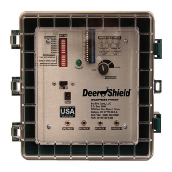
Your complete Deer
Shield Super Pro kit
includes a con trol unit,
power ad apter, ba t t ery
cable with clips and
up to four separate
PA horn speakers.
Open the con trol unit
by pressing backward
on the two latches on
the side of the box.
Prior to operation, plug
the power cable into
the power jack on the
control unit, and the
Fig. 1
speaker plugs into the
speaker jacks, then route the speaker and power
cables from their respective jacks on the control
panel down through the slotted rubber grommet
and through the opening in the lower part of the
enclosure, see Fig. 1.
IM POR TANT NOTE: Be certain that
the OFF - ON switch is in the OFF
po si tion and the volume control is set
to the minimum (LOW) vol ume level
(coun ter clock wise) as shown in Fig.
2 while plugging the speaker and
power cords into the control unit.
INSTALLATION
1) Use the mounting hardware (included) to mount
the control unit box to a wall, post or other vertical
surface.
2) Plug the power adapter into an electrical outlet
or attach the battery clip as sem bly to a 12V
battery.
The other end of the cable should
already be plugged into the power jack located
below POWER on the front panel of the con trol
unit box.
3) Mount the speaker(s) on a pole, post or surface
about 3 feet above any crops or foliage. Aim the
speakers to cover the area to be protected, with
emphasis on regular deer access points.
4) Set the Recordings, Mode Settings, Time
Off Interval, Time of Operation, Random and
Speakers Used Switches to the desired settings.
(See "PRO GRAM MING YOUR DEER SHIELD"
for complete details on how to program your
digital deer repeller).
5) Make sure the volume setting is set to LOW (all
the way counterclockwise).
6) Slide the OFF-ON power switch to the ON
position.
The unit may take a few seconds
before starting.
7) Adjust the volume to the desired level.
8) Close the cover and latch shut.
PROGRAMMING YOUR DEER SHIELD
To program your Deer Shield Super Pro unit
"RECORDINGS"). A switch is ON if the switch is
moved to the right-hand side by sliding the switch
to the right. The switch is OFF when moved to the
left-hand side.
Fig. 2
RECORDING SWITCH
corresponds with the deer sound descriptions listed
on the foil label located on the EPROM board to the
right of the switch arrays. Deer Shield Super Pro is
®
you will need a small screw-
driver, toothpick, or other
small, rigid object to slide the
switches in the switch array.
The switch arrays are the
switch banks located in the top
left corner of the unit (under
The Recordings switches
are the first eight switches
in the top switch array.
Each switch has a Sound
number to the left of it that
designed to play each selected sound at a different
randomly selected frequency each time it plays
that sound. This feature is designed to add to the
effectiveness of the unit and is independent of the
Random Operation Switch Setting.
NOTE: The Deer Shield Super Pro features a replaceable EPROM board
and chip. Notice that the sounds included on your Deer Shield Super Pro unit
are listed on a silver foil label affixed to the chip. To remove, simply pull the
EPROM board and chip straight out from the embedded socket. Then insert a
different EPROM board and chip by pressing firmly straight into the socket.
MODE SETTING SWITCHES
The Mode Settings switches
are the next five switches
which control the various
modes of operation: such as
the amount of time between
playing various deer distress and alarm sounds,
when the unit will operate (Day Only, Night Only,
or 24-Hours), whether the unit will operate in the
Random Mode.
Switch
Mode or Function
1
Sets the Time Off Interval
2
Sets the Time Off Interval
3
Sets the Time the unit plays
4
Sets the Time the unit plays
5
Turns Random Mode On or Off
TIME OFF INTERVAL SWITCHES
The two Time Off Interval
switches are located just
below
the
Switches
in
Settings switch array. These switches control the
length of time the unit will delay between recorded
sounds.
Please note that the unit will play for
approximately 48 seconds each time it cycles on (the
selected recordings will play either sequentially or
non-sequentially, depending on the Random Mode
setting) then it will go into a delay. The time the unit
stays off depends on the Time Off and the Random
Mode settings. If the unit is op er at ing in Random
Mode, the unit will delay anywhere from the min i mum
value to the maximum value for that Time Off setting
(see below). If the unit is not in Ran dom Mode, it will
delay only the minimum value. To set the Time Off
interval (or delay interval), use the following settings
on switches 1 and 2 in the mode function settings.
Recordings
the
Mode
Advertisement
Table of Contents

Related Manuals for Deer Shield SUPER PRO

Summary of Contents for Deer Shield SUPER PRO
- Page 1 NOTE: The Deer Shield Super Pro features a replaceable EPROM board and chip. Notice that the sounds included on your Deer Shield Super Pro unit are listed on a silver foil label affixed to the chip. To remove, simply pull the...
- Page 2 © 2011 Deer Shield operate. Slide the switch to the ON position to ® Super Pro from the makers of Bird Gard. Deer Shield ® from Speaker 1 to Speaker 4 (See Speaker Used is a registered trademark. EPA Establishment Number 075130-OR-001 start the unit.
Need help?
Do you have a question about the SUPER PRO and is the answer not in the manual?
Questions and answers