Table of Contents
Advertisement
Quick Links
USER GUIDE bikecharger model RPD 501
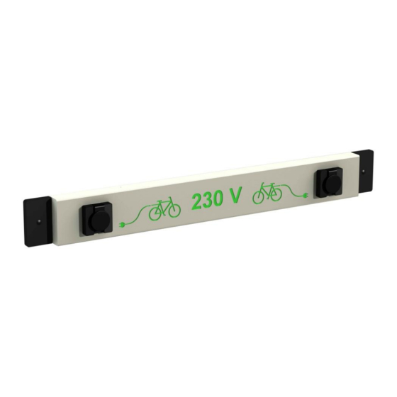
1. Two available models:
1
Model 501 basic (sockets mennekes-schuko M11162 or since 2017 ABLsursum schuko 1662002
With standard logos
Model 501 security (sockets mennekes mono NF e-mobility)
Example: on demand different
logos are possible
Raepsaet product design bvba - since 1989 - nacebel 71121 - RSZ 000/1699918 20 - PC 209.069
Schaapschuur 4 / 1
TEL: +32 (0) 53/66.00.49
RPR Brussel – BTW-VAT: BE 0438.468.506
------------------------------------------------------ www.raepsaet.be ------------------------------------------------------
(Save and read carefully before installation)
B-1790 AFFLIGEM
FAX: +32 (0) 53/66.00.46
BIC:KREDBEBB
V20200521 – 5pgs
BELGIUM
MAIL:
post@raepsaet.be
IBAN BE48 7350 4245 1127
Advertisement
Table of Contents

Summary of Contents for Raepsaet Mechanics RPD 501
- Page 1 USER GUIDE bikecharger model RPD 501 V20200521 – 5pgs (Save and read carefully before installation) 1. Two available models: Model 501 basic (sockets mennekes-schuko M11162 or since 2017 ABLsursum schuko 1662002 With standard logos Model 501 security (sockets mennekes mono NF e-mobility)
- Page 2 2. Description. Wall mounted charger 230V with two mono electrical sockets 16A/250V • Use: both in-and outside. • Available in basic- and securitymodel and colored logo. • With clear signs for simple use. • Sturdy construction in corrosion resistant and weatherproof materials. •...
- Page 3 Mechanical information Space for earthing Mounting holes Opening with plug access to wiring Opening for cable and cover Technical info cap for swivel 6. Overview of parts Pre-assembled and wired: -charger housing with colored engraving -two electrical plugs -two wall-mounting covercaps -wallplate -plug/opening back -pushwire connector ( already connected to...
- Page 4 7. Preparation installation and connection Remove covercaps to reach mounting holes In case of standard connection (bottom), remove gland screw cap and replace by cable gland M20, insert cable and connect (since 2017 cable gland is mounted standard) Remove cap for entrance to inside housing for connection of electrical wires.
- Page 5 9. Mounting against a wall (beware: a flat surface is mandatory) Place with 4 screws cil head Ø 5 mm max and lenght 50 mm min. Adapt screwsize and - lenght to surface . Anchor firmly. Place wall mounting cover caps on the backplate with original screws Put plugs in screw holes Raepsaet product design bvba - since 1989 - nacebel 71121 - RSZ 000/1699918 20 - PC 209.069...
Need help?
Do you have a question about the RPD 501 and is the answer not in the manual?
Questions and answers