
Related Manuals for Anyuta Bleriot XI-2 Balkan Wars & WWI

Summary of Contents for Anyuta Bleriot XI-2 Balkan Wars & WWI
- Page 2 ‘d like you to know that Anyuta 3D will be always next to you for anything you might need in order to build a realistic scale model for your showcase.
- Page 3 Fuel drums & jerrycans, fire extinguisher, wheel chokes etc) are not included into this model kit and should be purchased separately by “ANYUTA 3d print creations” products catalog. Please follow the step-by- step model kit building instructions. Due to parts complexity, the kit is...
- Page 4 The scale model kit contains 48 parts, 3D printed with Frosted Ultra Detail matte translucent plastic material. Please check & identify each part closely before proceeding to building process. Cyanoacrylate glue is recommended for best results.
- Page 5 These are the front and the rear fuselage frame sections. On real Blériot XI and XI-2 WWI airplanes, fuselage was covered by aluminum, plywood & doped fabric over the wooden frame. Be sure to check & prepare the fuselage parts before proceeding next.
- Page 6 Due to fact that fuselage consists of front & rear sections, it is necessary to reinforce the build. Use a common stainless steel sewing needle (approx 50mm long x 1mm wide) and remove bolt & tip (red colour marked). Steel pin should be 40mm long.
- Page 7 Prepare four steel pins & insert them through slots on rear frame section’s beams as shown on above screenshot. Make sure that fuselage frame section’s beam slots are clear, so that the metal pins can penetrate to a depth equal to half their length.
- Page 8 This is how the rear fuselage frame section should look like with the four metal pins wedged into beam slots. Notice that steel pins should protrude about half of their length (approx 18 to 20mm) just as much they are wedged into the rear frame beams.
- Page 9 As soon as the four steel pins are simultaneously aligned onto front fuselage frame slots, slide carefully the rear frame section forward (marked with the red arrows) to fit pins in place. Then, secure the build by adding a drop of cyanoacrylate super glue.
- Page 10 This is how the fuselage should look like when the front & rear sections correctly assembled to fit onto each other. The metal pins should be equally wedged into each frame section in order to effectively support parts to be glued & reinforce the build.
- Page 11 These are the fuel & oil tank caps. If you intend to leave the fuel or oil tanks opened and place filler caps nearby, the red colour marked sprue parts should be carefully removed with modeling knife with a sharp blade. The kit contains three (3) filler caps.
- Page 12 These are the left and right cylindrical shaped engine oil tanks, mounted under the aluminum hood infront of pilot’s flight controls & gauges. Be sure you identify parts correctly before proceeding next step. The kit contains two (2) cylindrical oil tanks.
- Page 13 Insert the two cylindrical engine oil tanks carefully through the front opening and place them such way to align on the semicircular brackets, underneath the aluminum hood in front of pilot’s cockpit. Be careful while inserting tanks to prevent fracture...
- Page 14 As soon as each cylindrical engine oil tank is correctly aligned on the semicircular brackets underneath the aluminum hood, move upwards (marked with red arrows), as shown on picture. Then, secure in place by adding a drop of cyanoacrylate super glue.
- Page 15 This is how the two cylindrical shaped oil tanks should look like when correctly installed underneath the aluminum hood. Dry fit testing is recommended before final assembling. Secure in place with a drop of cyanoacrylate super glue for best results...
- Page 16 If the two oil tanks are correctly installed underneath the aluminum hood, the right tank’s inverse breather pipe (red circle marked) should clearly protrude from hood opening & both filler caps should be visible & alligned under front circular openings...
- Page 17 These are the 7-cylinder rotary engine’s front & rear sections. Due the engine’s size, it cannot pass through the front opening and be installed in place as one piece. Therefore, it will be assembled in stages. Be sure you identify these parts correctly.
- Page 18 Insert the engine’s rear section carefully through the frame opening & place it such way to align bracket on the second vertical beams. Be careful while inserting the part, to prevent fracture or damage on the previously installed cylindrical oil tanks.
- Page 19 This is how the engine’s rear section should look like when it’s bracket is correctly aligned on the second vertical frame beams (left & right) & placed under oil tanks. Exact bracket height will be later adjusted depending on front section installation.
- Page 20 Insert engine’s front section through frame opening and slide backwards (red arrow marked) to fit on engine’s rear section. Since engine’s diameter is wider than frame opening, you may need to twist part a little, to pass between first left & right beams.
- Page 21 This is how engine should look like when correctly assembled & instaled. Notice that engine’s front section should be alligned between first & second row of frame beams. Engine’s cylinders block should hypothetically freely spin without hitting the frame.
- Page 22 This is how engine’s cylinders block looks like when seen from the front side. If the engine parts are correctly assembled & instaled in place, the cylinders block should hypothetically freely spin between first & second row of beams without hitting frame...
- Page 23 As soon as the rotary engine is corectly installed, place the square shaped engine’s front cover as marked with the four red arrows. Slide backwards as soon as shaft head is aligned on engine’s slot as shown on picture. Secure in place with super glue.
- Page 24 This is how the engine & square shaped cover look like when everything is correctly assembled, aligned & instaled. Engine is safely supported on square shaped cover at front & on rear section bracket which is already glued on second row of frame beams...
- Page 25 These are the engine’s bubble shaped side covers. They look identical but are not. The right one embossed rivets, is intended to be instaled on frame, while the left can be removed in order to let engine be visible from the side & rivets remain nailed on frame...
- Page 26 Align the bubble shaped side covers on engine’s cylinders block & move the parts sideways (red arrows marked) to attach on frame. The left cover can be excluded to provide a clear view on engine’s details from the side. Secure in place with super glue...
- Page 27 This is how the engine’s bubble shaped side covers look like when correctly aligned & instaled in place. The engine’s cylinders block should hypothetically freely spin without hitting any frame part while being protected by the bubble shaped side covers...
- Page 28 This is the 2-bladed Chauvière Intégrale propeler, approx 156mm wide from tip to tip. It is intended to be attached on the front end of previously installed engine’s square shaped cover. Be sure you identify part correctly. The kit contains one (1) propeler.
- Page 29 As soon as the 2-bladed main propeler’s slot placed on rear side is carefully aligned right onto the 7-cylinders rotary engine’s shaft, slide the propeler backwards (red arrow marked) to fit & secure in place by adding a drop of cyanoacrylate super glue.
- Page 30 These are the fixed non-retractable undercarriage 47.3 x 5.2 mm sized spoked wheels with solid tyres. Be sure you identify parts correctly before proceeding to next assembly step. The model kit contains two (2) main spoked wheels with 32 spokes each.
- Page 31 Attach two (2) main landing gear spoked wheels to non-retractable undercarriage as shown on the screenshot (red arrows marked). Be carefull while installing spoked wheels to avoid plastic part fracture. Cyanoacrylate superglue is mostly recomended...
- Page 32 This is how the two main landing gear spoked wheels should look like when correctly aligned & instaled on struts. Undercarriage consisted of the wheels at the front of airplane frame and slanted located skid mounted slightly behind midpoint of fuselage...
- Page 33 This is the cylindrical shaped fuel tank, transversely mounted between the pilot’s and the observer’s seats. Be sure you identify part correctly before proceeding to next step. The kit contains one (1) cylindrical shaped fuel tank with proper filler cap.
- Page 34 Insert the cylindrical shaped fuel tank through the side opening between observer’s & pilot’s seats. Place it such way so the support bracket rest on transversal beams of frame. The fuel tank’s fillercap should be aligned under circular opening on hood.
- Page 35 This is how the cylindrical shaped fuel tank should look like when correctly aligned & installed on transversal beams of frame. Dry fit testing is recommended before final assembling. Secure part with a drop of cyanoacrylate superglue for best result...
- Page 36 These parts are the rudder pedals & steering transmission located on pilot’s cockpit. They are linked together through opening on cockpit’s floor. Be sure you identify the parts correctly. Kit contains one (1) rudder pedal set & one (1) steering transmission...
- Page 37 Insert the steering transmission’s pin upwards through the cockpit floor opening & slide into rudder pedals set’s slot as shown on the screenshot (red arrows marked). Be carefull while installing rudder pedals and transmission to avoid plastic fracture...
- Page 38 This is how the rudder pedals set should look like when correctly aligned on pin and installed on the pilot’s cockpit floor. Dry fit testing is recommended before the final assembling. Secure the part with a drop of cyanoacrylate superglue for best results...
- Page 39 This is how the steering transmission should look like when correctly aligned and installed under the pilot’s cockpit floor. Dry fit testing is recommended before the final assembling. Secure part with a cyanoacrylate super glue drop for best results.
- Page 40 These are the perforated crew seats for pilot & observer to be installed in tandem, one behind the other in cockpit. Be sure you identify these parts correctly before proceeding to next assembly step. The model kit contains two (2) identical crew seats.
- Page 41 Insert the crew seats through the cockpit upper openings and align them in such way so the supporting brackets rest on the left and right longitudinal frame beams (red arrows marked) as shown on picture. Secure with a drop of cyanoacrylate super glue.
- Page 42 This is how the front & rear crew seats tandem arrangement should look like when correctly aligned & installed on the left and right longitudinal frame beams. Dry fit testing is recommended before glueing the crew seats on cockpit floor frame beams.
- Page 43 These are the chart roller boards for the pilot and the observer. These map roller boards are intended to be instaled on the center of the instrument panel, right in front of each crew member. The model kit contains two (2) identical map roller boards...
- Page 44 Use your home printer to create a realistic military map printout under scale. Then, cut two 22 x 14mm sized paper sheets to be rolled over the map boards to replicate the charts used by the pilot and the observer. Paper sheets are not included into kit...
- Page 45 Rollwrap the 22 x 14mm sized paper sheets in such way so that the edges follow the shape of the map boards. Paper’s long ends can be easily rolled under transversal beams & hide there as shown on picture. Rollwrap paper until best result is achieved.
- Page 46 Rollwrap the 22 x 14mm sized paper sheets in such way so that the edges follow the shape of the map boards. Paper’s long ends can be easily rolled under transversal beams & hide there as shown on picture. Rollwrap paper until best result is achieved.
- Page 47 Insert the map rollers through the cockpit upper openings and align them in such way so the boards rest angled on the center of the instrument panel, right in front of pilot & observer. Secure with a drop of cyanoacrylate super glue for best results...
- Page 48 This is how the map roller boards should look like when correctly aligned & angled installed on the center of front & rear cockpit instrument panels. Dry fit testing is mostly recommended before glueing map roller boards on the center of crew panels.
- Page 49 This is the magnetic compass gauge, intended to be instaled on the front-right of the pilot’s instrument panel, right next to previously installed map roller board. Be sure you identify this tiny part correctly. The kit contains one (1) magnetic compass gauge.
- Page 50 This is the engine’s rpm tachometer, intended to be instaled on the front-left of the pilot’s instrument panel, next to the previously installed map roller board. Be sure you identify this tiny part correctly. The kit contains one (1) engine’s rpm tachometer.
- Page 51 This is a clock intended to be instaled on the upper front-left of the instrument panel, right underneath the aluminum hood and next to previously installed engine’s rpm tachometer. Be sure you identify this part correctly. Kit contains one (1) clock.
- Page 52 This is how the clock (marked into red circle) and other gauges should look like when everything is correctly aligned & installed on the front cockpit’s instrument panel. Dry fit testing is mostly recommended before glueing gauges on the instrument panel.
- Page 53 These parts are the main control levers found into the Blériot XI-2 airplane front cockpit. The kit contains one (1) fuel flow & oil pump switch board, one (1) main flight control & trim column and one (1) throttle lever for the 7-cylinders rotary engine.
- Page 54 Insert main flight control column through the front cockpit upper opening and align it such way so the lower end fit right into U-shaped bracket of roll & pitch control transmission bar. Secure part with drop of cyanoacrylate superglue for best results...
- Page 55 Insert lower end of the flight control column into U-shaped bracket of roll & pitch transmission bar (red arrow marked) as shown on picture. Dry fit testing is mostly recommended before glueing the flight control column into the U-shaped bracket bar...
- Page 56 This is how the flight control column (marked into red circle) should look like when everything is correctly aligned & installed in place. Notice nearby & already instaled rudder pedals, pilot’s perforated seat & gauges attached on front instruments panel...
- Page 57 Move the throttle lever part forward and align it’s jag onto the U-shaped notch slot placed on vertical beam (red arrow marked) of fuselage frame, as shown on picture. Slide to fit in place & secure with cyanoacrylate super glue for best results...
- Page 58 This is how the engine’s throttle lever (marked into red circle) should look like when everything is correctly aligned & installed in place. Notice nearby & already instaled rudder pedals, pilot’s perforated seat, flight control column and flight instruments...
- Page 59 Move the fuel flow & oil pump control switch board upwards and align it onto the upper left longitudinal beam (red arrow marked) of the fuselage frame, as shown on picture. Slide to fit in place & secure with cyanoacrylate super glue for best results...
- Page 60 This is how the fuel flow & oil pump control switch board (marked into red circle) should look like when everything is correctly aligned & installed in place. Notice nearby & already instaled flight control column, chart roller board & instruments.
- Page 61 This is the map case and contains spare charts, mission notebook & printed matterial for the crew. This map case part is intended to be instaled on the lower right side of the rear cockpit, next to the observer’s seat. The model kit contains one (1) map case.
- Page 62 Insert map case through right side opening of the observer’s cockpit area. Place it such way so the map case stands upright on cockpit floor & aligned next to lower- right longitudinal beam (red arrow marked) of the fuselage frame as shown on picture...
- Page 63 This is how the map case (marked into red circle) should look like when everything is correctly aligned and installed in place. Notice nearby & already instaled fuel tank, observer’s perforated seat & chart roller board attached under the aluminum hood.
- Page 64 Align the teardrop-shaped wingtip frame onto the main wing part & move sideways (red arrows marked) to attach these two items as one piece, as shown on screenshot. Secure wing parts in place with a drop of cyanoacrylate super glue for best results.
- Page 65 Align the pins found on the left and right wing roots on the proper frame’s slots & move the wings sideways (red arrows marked) to attach them on fuselage as shown on screenshot. Secure the wings in place with cyanoacrylate superglue for best results...
- Page 66 Align the pins found on the left and right wing roots on the proper frame’s slots & move the wings sideways (red arrows marked) to attach them on fuselage as shown on screenshot. Secure the wings in place with cyanoacrylate superglue for best results...
- Page 67 Align the jags found on the front-upper side of elevator, right next to the frame’s knobs & move elevator wing upwards (red arrows marked) to attach it on fuselage as shown on screenshot. Secure elevator’s wing in place with cyanoacrylate super glue.
- Page 68 This is how the elevator wing should look like when everything is correctly aligned & installed in place. Notice that elevator’s forward upper jags (red circle marked) are attached on fuselage frame knobs from outside & the rear upper jags from the inside.
- Page 69 This is how the elevator wing should look like when everything is correctly aligned & installed in place. Wings & elevator may not be stable enough at this point. Proper wire rigging & bracing later will result to solid rock wing stability & corect balance.
- Page 70 These parts are the elevator wing’s support beams. These beams are intended to be installed by angle on the upper side of the elevator wing, providing efficient stability on build. The kit contains four (2) elevator wing support beams in two identical pairs.
- Page 71 This is how the elevator wing and the two pairs of the angled support beams should look like when everything is correctly aligned & installed in place. Notice that the elevator wing’s support beams are attached on main horizontal stabilizer structure.
- Page 72 Align the “all-moving” rudder fin’s U-shaped brackets onto rear end vertical shaft and move the rudder fin part forward (red arrows marked) to attach it on fuselage frame as shown on screenshot. Secure rudder in place with cyanoacrylate super glue...
- Page 73 This is how the “all-moving” rudder fin should look like when everything is correctly aligned & installed in place. Dry fit testing is mostly recommended before gluing. Notice nearby & already instaled elevator wing with the angled supporting beam pairs...
- Page 74 The “all-moving” rudder fin can be glued in neutral position or tilted with max 40° deflection. Notice that if the rudder fin is tilted left or right, then all proper flight control wires & the rudder pedals in front cockpit should be positioned accordingly.
- Page 75 These are the power generator and the airspeed indicator, both mounted outside of cockpit. The red colour marked sprue part should be removed with modeling knife with sharp blade. The kit contains one (1) power generator and one (1) airspeed indicator.
- Page 76 As soon as the pin on the upper side of the power generator is correctly aligned under the slot found on upper part of landing gear right strut, move upwards (red arrow marked) as shown on picture and secure in place with cyanoacrylate super glue...
- Page 77 This is how the power generator should look like when everything is correctly aligned & installed in place. Notice that the little propeler (red circle marked) should keep facing forward. Dry fit testing is recommended before applying superglue...
- Page 78 Align the airspeed indicator on left teardrop-shaped wing frame & move downwards (red arrow marked) as shown on the picture. Attach the airspeed indicator part where the 4 teardrop-shaped wing frame is intersecting the wing’s transverse upper beam.
- Page 79 This is how the airspeed indicator part should look like when everything is correctly aligned & installed in place. Notice that when the plane is grounded and there is no air flow present, the sensor’s square plate tilts forward and the needle points zero.
- Page 80 Although wire rigging & bracing is not mandatory, it is necessary for few parts such as wings or undercarriage struts to be properly rigged to obtain weighted balance, correct stability & solid rock build. From now on, rigging lines will be marked as blue...
- Page 81 These are the rubber bands vertically mounted in quartets, in circumferential array around each undercarriage strut to act as landing shock absorbers. The kit contains nine (9) cylindrical rubber bands. Only the eigth are needed while the ninth is a spare...
- Page 82 This is how the vertically aligned rubber bands should look like when correctly installed in circumferential array around strut. Blue marked wire is passing through each rubber band & loops over the upper & lower D-rings on each front or rear side.
- Page 83 This is how the vertically aligned rubber bands should look like when correctly installed in circumferential array around strut. Blue marked wire is passing through each rubber band & loops over the upper & lower D-rings on each front or rear side.
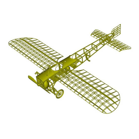
- Page 84 This is how the 1/15 scale Blériot XI-2 model should look like when fully built with all the proper wire rigging & bracing work (blue marked) is completed as shown on picture. Rigging is necessary to obtain weighted balance, stability & solid rock build.
- Page 85 This is (side view) how the 1/15 scale Blériot XI-2 model should look like when fully built with all the proper wire rigging & bracing work completed. Rigging process is hard but necessary to obtain weighted balance, stability & solid rock build for model...
- Page 86 This is (front view) how the 1/15 scale Blériot XI-2 model should look like when fully built with all the proper wire rigging & bracing work completed. Rigging process is hard but necessary to obtain weighted balance, stability & solid rock build for model...
- Page 87 This is (upper view) how the 1/15 scale Blériot XI-2 model should look like when fully built with all the proper wire rigging & bracing work completed. Rigging process is hard but necessary to obtain weighted balance, stability & solid rock build for model...
Need help?
Do you have a question about the Bleriot XI-2 Balkan Wars & WWI and is the answer not in the manual?
Questions and answers