Trafox SUPERINTEND IM-01.MED Instructions For Installation And Use Manual
Imd insulation monitoring device for non-grounded (it) electrical networks for medical locations
Hide thumbs
Also See for SUPERINTEND IM-01.MED:
- Instructions for installation and use manual (85 pages)
Table of Contents
Advertisement
Quick Links
SUPERINTEND IM-01.MED/IC-01/TC-01/RD-
01/PEC-01
IMD Insulation Monitoring device for non-grounded (IT) electrical
networks for medical locations
Instructions for installation and use v1.15
AC/DC
MED
Superintend IM-01.MED/IC-01/TC-01/RD-01/PEC-01 Manual v1.15 English
Rights to modify the content reserved
© Copyright Muuntosähkö Oy - Trafox 15.9.2020
Advertisement
Table of Contents

Related Manuals for Trafox SUPERINTEND IM-01.MED

Summary of Contents for Trafox SUPERINTEND IM-01.MED
- Page 1 SUPERINTEND IM-01.MED/IC-01/TC-01/RD- 01/PEC-01 IMD Insulation Monitoring device for non-grounded (IT) electrical networks for medical locations Instructions for installation and use v1.15 AC/DC Superintend IM-01.MED/IC-01/TC-01/RD-01/PEC-01 Manual v1.15 English Rights to modify the content reserved © Copyright Muuntosähkö Oy - Trafox 15.9.2020...
-
Page 2: Table Of Contents
System fault mode ..................60 Setup mode ....................60 PEC-01 UNIT ....................61 CLT-01 UNIT ....................63 TECHNICAL SPECIFICATIONS ................65 IM-01.MED UNIT ....................65 PEC-01 UNIT ....................67 TC-01 and IC-01 UNITS ..................67 © Copyright Muuntosähkö Oy – Trafox Superintend IMD http://www.trafox.fi... - Page 3 QUICK INSTRUCTION TEMPLATES OF IC-01 AND TC-01 FOR MEDICAL LOCATIONS .. 71 QUICK INSTRUCTION TEMPLATE OF RD-01 FOR MEDICAL LOCATIONS ....72 IM-01.MED - QUICK INSTRUCTION FOR ACKNOWLEDGING ALARMS ...... 73 Superintend IMD © Copyright Muuntosähkö Oy - Trafox http://www.trafox.fi...
-
Page 4: Instructions
Such sections are marked with the symbol shown below. A symbol indicating possible danger. A description of the symbol may be placed on the device or provided in the instructions for use. © Copyright Muuntosähkö Oy – Trafox Superintend IMD http://www.trafox.fi... -
Page 5: System Description
DIN TS35 rail in the groove intended for the DIN TS35 rail on the back of the device and by pushing the bottom edge of the device backward until the retaining latch clicks into place. Superintend IMD © Copyright Muuntosähkö Oy - Trafox http://www.trafox.fi... - Page 6 The Ethernet cable is connected to the RJ45 connector in the front panel. Before connecting the device to the local area network, set the TCP/IP parameters suitable for the LAN (SETUP→IP Settings). © Copyright Muuntosähkö Oy – Trafox Superintend IMD http://www.trafox.fi...
- Page 7 RS-485 data- (two-way data/twisted pair 1) RS-485 network and 12V connection earth, twisted pair 2 Chaining of the RS-485 cable shield +12V +12V input from the IM-01.MED unit, twisted pair 2 Superintend IMD © Copyright Muuntosähkö Oy - Trafox http://www.trafox.fi...
- Page 8 Figure 1. System connection. © Copyright Muuntosähkö Oy – Trafox Superintend IMD http://www.trafox.fi...
-
Page 9: Rs-485 Network Connection
The cable shield is also connected to each unit and connected to protective earth in the IM-01.MED unit. In other devices, the shields are floating and the connector only acts as a joining connector between two shields. Superintend IMD © Copyright Muuntosähkö Oy - Trafox http://www.trafox.fi... - Page 10 No more than two RS-485 cables may be installed in any unit. Otherwise, the bus does not form an uninterrupted chain but has branches. The shields of the cables are connected to the SH terminal of each unit. © Copyright Muuntosähkö Oy – Trafox Superintend IMD http://www.trafox.fi...
-
Page 11: Hw Settings Of The Tc-01 And Ic-01 Units
A = 10, B = 11, C = 12, D = 13, E = 14 and F = 15. The other addresses (0–9) function in the manner marked on the switch. Superintend IMD © Copyright Muuntosähkö Oy - Trafox http://www.trafox.fi... -
Page 12: Hw Settings Of The Rd-01 Unit
The order of pins in RD-01 is shown in the Figure below. +12V - SH The pins to be connected by means of a terminator jumper © Copyright Muuntosähkö Oy – Trafox Superintend IMD http://www.trafox.fi... -
Page 13: Hw Settings Of The Pec-01 Unit
To open the cover: pry the cover loose with a screwdriver here and remove the cover Terminator jumper Superintend IMD © Copyright Muuntosähkö Oy - Trafox http://www.trafox.fi... -
Page 14: Hw Settings Of The Clt-01 Unit
If a microSD memory card has been connected to the device, enable it (SETUP→Mem Card: in use) and restart the device. Set the correct time. (SETUP→Time) Set the load current measurement and isolation transformer parameters (SETUP→ TranSize, Nom.Cur) © Copyright Muuntosähkö Oy – Trafox Superintend IMD http://www.trafox.fi... - Page 15 When needed, set the range for CLT-01 unit’s current loop output (SETUP→LoopCurr) When needed, set the TCP/IP parameters (SETUP→IP Settings) A more detailed description of the configuration is provided in the Manual section “SETUP menu”. Superintend IMD © Copyright Muuntosähkö Oy - Trafox http://www.trafox.fi...
-
Page 16: Use
Setup menu. They are Excel-compatible text files, which can be transferred to any computer for more detailed analysis. For more detailed information, see section “Log files”. If the © Copyright Muuntosähkö Oy – Trafox Superintend IMD http://www.trafox.fi... -
Page 17: Menu Structure
B button at any menu level item. The LED lights, in addition to the LCD display, indicate the selection in the menu in question. The menus can be browsed up and down with the buttons. Access to the Setup menu is password-protected. Superintend IMD © Copyright Muuntosähkö Oy - Trafox http://www.trafox.fi... - Page 18 If there are several parameters to be changed in the same screen, you can move to the next one by pressing the button. After the editing is completed, press the T button, after which the values © Copyright Muuntosähkö Oy – Trafox Superintend IMD http://www.trafox.fi...
-
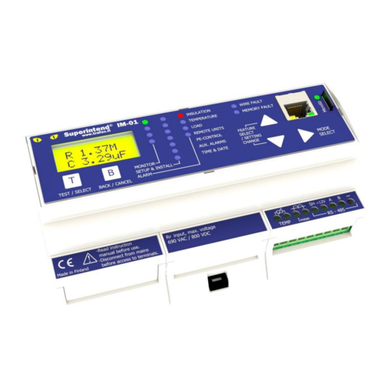
Page 19: Monitor Menu
IT network’s insulation resistance and capacitance in relation to protective earth. Displayed in kOhms and micro farads. Temperature of the isolation transformer in degrees. Secondary current of the isolation transformer. Displayed in a percentage of the transformer’s nominal current. Superintend IMD © Copyright Muuntosähkö Oy - Trafox http://www.trafox.fi... - Page 20 Test OK; otherwise the text shown in Test FAILED, and an insulation fault alarm is given to indicate that the insulation resistance can no longer be measured. The Monitor menu functions as follows: © Copyright Muuntosähkö Oy – Trafox Superintend IMD http://www.trafox.fi...
- Page 21 Superintend IMD © Copyright Muuntosähkö Oy - Trafox http://www.trafox.fi...
-
Page 22: Alarm Menu
RESET switch located on the PEC-01 unit. This also inactivates the alarm in the IM-01.MED unit. All fixed faults can also be acknowledged on one go by means of the Alarm reset function in the Monitor menu. © Copyright Muuntosähkö Oy – Trafox Superintend IMD http://www.trafox.fi... - Page 23 Superintend IMD © Copyright Muuntosähkö Oy - Trafox http://www.trafox.fi...
- Page 24 The largest value measured during the fault, the alarm limit's set value and the fault start time are displayed. The temperature alarm is active. The highest temperature measured during the fault is 93 degrees and the alarm limit is 90 degrees. © Copyright Muuntosähkö Oy – Trafox Superintend IMD http://www.trafox.fi...
- Page 25 The InstUnit screen mode shows the unit which caused the error and text MIS if the device is missing. Such a unit is detected within four seconds. IC-01 unit 9 is missing. Alarm is active, the device disappeared from the system at 1:12 pm. Superintend IMD © Copyright Muuntosähkö Oy - Trafox http://www.trafox.fi...
- Page 26 The fault is caused by a depleted battery. The fault can only be acknowledged once the time has been set. The device battery cannot be changed by the © Copyright Muuntosähkö Oy – Trafox Superintend IMD http://www.trafox.fi...
-
Page 27: Setup Menu
EEPROM memory of the IM-01.MED unit. The device addresses and a list of the PE channels’ resistances are saved after the first Network Scan. The microSD card’s setup log always includes a time-stamped copy of the EEPROM values. Superintend IMD © Copyright Muuntosähkö Oy - Trafox http://www.trafox.fi... - Page 28 © Copyright Muuntosähkö Oy – Trafox Superintend IMD http://www.trafox.fi...
- Page 29 5A. The setup range is 10– 100 A. NOMINAL CURRENT: The nominal current of the isolation transformer at full power. SETUP RANGE 1–100 A. Superintend IMD © Copyright Muuntosähkö Oy - Trafox http://www.trafox.fi...
- Page 30 A more detailed description is provided in the IP settings section. LOOP CURRENT: This setting determines the output current range of any current loop transmitters CLT-01 connected to the RS-485 bus. The options are 0…20 mA and 4…20 mA. © Copyright Muuntosähkö Oy – Trafox Superintend IMD http://www.trafox.fi...
-
Page 31: Network Scan
If the system includes even one defective device, the Network Scan results should not be approved until the fault has been fixed. Such faults include, for example: A defective remote unit A defective channel in the PE unit Superintend IMD © Copyright Muuntosähkö Oy - Trafox http://www.trafox.fi... - Page 32 Resistance that is too high in a PE unit channel Duplicate addresses © Copyright Muuntosähkö Oy – Trafox Superintend IMD http://www.trafox.fi...
- Page 33 The IC-01 unit 8 is connected, and it was also included in an earlier approved configuration. The TC-01 unit 8 is new. The RD-01 unit 2 has been removed from the previous approved configuration. Superintend IMD © Copyright Muuntosähkö Oy - Trafox http://www.trafox.fi...
-
Page 34: Network View / Adding And Removing Devices
(when adding a PE unit, also all its channels being used) must be approved one by one. The values that are not approved separately will retain their previous value. The screen mode of the Network View is similar to that of the Network Scan mode. © Copyright Muuntosähkö Oy – Trafox Superintend IMD http://www.trafox.fi... - Page 35 Superintend IMD © Copyright Muuntosähkö Oy - Trafox http://www.trafox.fi...
-
Page 36: Aux. Alarm Mask
(in the case of a sum alarm “S”) cause an alarm. The parameter order is as shown above. The setting is changed on the edit level by setting the ON/OFF mode with the buttons and approving the changes with the T button. © Copyright Muuntosähkö Oy – Trafox Superintend IMD http://www.trafox.fi... - Page 37 Superintend IMD © Copyright Muuntosähkö Oy - Trafox http://www.trafox.fi...
-
Page 38: Ip Settings
If parameters that are not suitable for the local area network being used are entered in the settings, problems may occur in the functioning of the entire LAN to be used. © Copyright Muuntosähkö Oy – Trafox Superintend IMD http://www.trafox.fi... -
Page 39: Errors
INS(4) wire is disconnected FAULT IM-01.MED is not capable ALARM of measuring insulation INSULATION INSULATION(5) MeasFail(5) INS(5) resistance and FAULT capacitance System fault (manual INSULATION ALARM INSULATION Sys Test test) FAULT Superintend IMD © Copyright Muuntosähkö Oy - Trafox http://www.trafox.fi... -
Page 40: Log Files
NAMEMMYY.TXT, where NAME is the file type (EVNT, MEAS, STUP), MM is the month and YY is the year of archiving. For example, the file EVNT0215.TXT is an event file of the EVENTLOG.TXT file from February 2015. © Copyright Muuntosähkö Oy – Trafox Superintend IMD http://www.trafox.fi... -
Page 41: Event Log (Eventlog.txt)
Temperature Sensor Type Changed to NTC temperature sensor was Temperature Sensor Type Changed to Pt100 changed. The transformer’s temperature Temperature Sensor Calibrated [O1 ADP]->[O2 ADP] sensor of type Pt100 was calibrated. The old offset value Superintend IMD © Copyright Muuntosähkö Oy - Trafox http://www.trafox.fi... - Page 42 TG Ground Failure OFF and MG to PE is fine after a detected outage. The insulation resistance measurement cannot be Measure Failure ON performed due to an internal fault. © Copyright Muuntosähkö Oy – Trafox Superintend IMD http://www.trafox.fi...
- Page 43 The TC-01 unit configured in Missing TC Alarm ON [TCXX] the TC address XX is not responding. The TC-01 unit configured in Missing TC Alarm OFF [TCXX] TC address XX is responding Superintend IMD © Copyright Muuntosähkö Oy - Trafox http://www.trafox.fi...
- Page 44 PE address XX has been disconnected. The channel CC of the PEC-01 Missing PE Channel Alarm OFF [PEXX CHCC] unit configured in PE address XX has been restored from an © Copyright Muuntosähkö Oy – Trafox Superintend IMD http://www.trafox.fi...
- Page 45 5 A) was changed from N1 to N2. The value of the Nom.Cur parameter (the nominal System Parameter changed [Nom.Cur] [N1A]->[N2A] current of the isolation transformer) was changed Superintend IMD © Copyright Muuntosähkö Oy - Trafox http://www.trafox.fi...
- Page 46 N1 = the measured amplitude in volts with the range between L1, L2 volts. N2 = the measured group delay in radians with the limit between L3, L4 radians. © Copyright Muuntosähkö Oy – Trafox Superintend IMD http://www.trafox.fi...
-
Page 47: Measurement Log (Measlog.txt)
After that, detailed information on the measurements that are not needed in normal use is printed on the row. Therefore, they are not discussed here in greater detail. All fields are separated with tabs, so the file is easy to handle in Excel. Superintend IMD © Copyright Muuntosähkö Oy - Trafox http://www.trafox.fi... -
Page 48: Setup Log (Setuplog.txt)
[TranSize] = the provided nominal primary/secondary current of the current transformer (amperes) [Nom.Cur] = the provided nominal current of the isolation transformer (amperes) [AUXalarm] = a configuration of alarms that will activate the AUX alarm relay © Copyright Muuntosähkö Oy – Trafox Superintend IMD http://www.trafox.fi... -
Page 49: Modbus/Tcp Remote Control
Password of the local user uint16 none A three-digit password. Range 000…999. Default interface value 123. When needed, this can be used to prevent the parameters from being set through the Modbus/TCP. Superintend IMD © Copyright Muuntosähkö Oy - Trafox http://www.trafox.fi... - Page 50 The nominal value of the uint16 current transformer, the lowest allowed value of the device parameter The nominal value of the uint16 current transformer, the highest © Copyright Muuntosähkö Oy – Trafox Superintend IMD http://www.trafox.fi...
- Page 51 Bit mask: bit0…5 = PE unit channels CH1…CH6: if 1, the channel alarm is active bit8…13 = PE unit channels CH1…CH6: if 1, the channel alarm has been deactivated but not acknowledged Superintend IMD © Copyright Muuntosähkö Oy - Trafox http://www.trafox.fi...
- Page 52 Bit mask: bit0…5 = PE unit channels CH1…CH6: if 1, the channel alarm is active bit8…13 = PE unit channels CH1…CH6: if 1, the channel alarm has been deactivated but not acknowledged © Copyright Muuntosähkö Oy – Trafox Superintend IMD http://www.trafox.fi...
- Page 53 Isolation transformer nominal uint16 current, the device parameter resolution (jog) The type of the transformer’s uint16 none 0= NTC, 1=Pt100 temperature sensor Operating mode of the current uint16 none 0= 4–20mA, 1=0–20mA loop Superintend IMD © Copyright Muuntosähkö Oy - Trafox http://www.trafox.fi...
-
Page 54: Remote Control Units
SETUP menu. IC-01 also gives an alarm if the unit cannot connect to the IM-01.MED unit. In addition, the unit issues a warning if the system's insulation resistance is lower than the pre-alarm limit set. © Copyright Muuntosähkö Oy – Trafox Superintend IMD http://www.trafox.fi... - Page 55 Pressing the SYSTEM TEST button gives the IM-01.MED unit a command to perform the system test. If the test fails, the INSULATION FAULT LED indicator switches on. Superintend IMD © Copyright Muuntosähkö Oy - Trafox http://www.trafox.fi...
-
Page 56: Transformer Remote Alarm Unit Tc-01
The error is always unit-specific; in other words, it is only displayed in the affected unit. In the IM-01.MED unit, the error is displayed as a REMOTE UNITS error. © Copyright Muuntosähkö Oy – Trafox Superintend IMD http://www.trafox.fi... -
Page 57: Insulation Resistance And Transformer Remote Alarm Unit Rd-01
SETUP→PrInsLim. The ALARM LED blinks if the insulation resistance is lower than the limit provided, if the transformer’s load current or temperature limit is exceeded or if the Superintend IMD © Copyright Muuntosähkö Oy - Trafox http://www.trafox.fi... -
Page 58: Monitor Mode
Additionally, it displays the transformer load current, transformer temperature or insulation capacitance on the lower line. The value displayed on the lower line can be changed by shortly pressing the button. 472kΩ 472kΩ 30 °C 472kΩ 0.2uF © Copyright Muuntosähkö Oy – Trafox Superintend IMD http://www.trafox.fi... -
Page 59: Alarm Mode
M2 wire, or short-circuited insulation resistance) Noise Noise alarm T-sens 0 Alarm caused by disconnected temperature sensor measurement wire T-sens S Alarm caused by short circuited temperature sensor Superintend IMD © Copyright Muuntosähkö Oy - Trafox http://www.trafox.fi... -
Page 60: System Test Mode
The setup mode is entered by simultaneously pressing the MON/ALARM and buttons for 5 seconds in the monitor mode. The mode is used to define the RD-01 unit device address between 0 and 4 in accordance with the following diagram. © Copyright Muuntosähkö Oy – Trafox Superintend IMD http://www.trafox.fi... -
Page 61: Pec-01 Unit
(the table value multiplied by the percentage parameter PEalarm%), an alarm is given. The measurement range is 0…2.54 Ω. The detection of a measurement loop break is constantly on. Superintend IMD © Copyright Muuntosähkö Oy - Trafox http://www.trafox.fi... - Page 62 In other words, one of the channel LED indicators is always on if the channel has been configured for use. If the PEC-01 unit is in the SYSTEM FAIL mode, in other © Copyright Muuntosähkö Oy – Trafox Superintend IMD http://www.trafox.fi...
-
Page 63: Clt-01 Unit
If insulation resistance cannot be measured reliably, CLT-01 sends the current value 22mA The output current of CLT-01 as a function of insulation resistance at the loop current setting of 0…20 mA Superintend IMD © Copyright Muuntosähkö Oy - Trafox http://www.trafox.fi... - Page 64 If insulation resistance cannot be measured reliably, CLT-01 sends the current value 22mA The output current of CLT-01 as a function of insulation resistance at the loop current setting of 4…20 mA © Copyright Muuntosähkö Oy – Trafox Superintend IMD http://www.trafox.fi...
-
Page 65: Technical Specifications
Alarm limit [R ]: 50kΩ…1MΩ Relative uncertainty (22kΩ…5MΩ): ±15% Hysteresis: 5% The response time of the insulation level alarm as a function of the alarm limit and insulation capacitance Superintend IMD © Copyright Muuntosähkö Oy - Trafox http://www.trafox.fi... - Page 66 Not suitable for connecting in parallel Voltage test (IEC 61010-1:2010, Annex F): 2.2 kVAC EMC standards: EN61326-2-4, EN55011, EN61000-3-2, EN61000-4-2, EN61000- 4-3, EN61000-4-4, EN61000-4-5, EN61000-4-6, EN61000-4-11 Other standards: IEC61557-8, IEC61010-1:2010-3 © Copyright Muuntosähkö Oy – Trafox Superintend IMD http://www.trafox.fi...
-
Page 67: Pec-01 Unit
RS-485 speed 9600 bps Connector tightening torque: 0.45…0.5 Nm Weight: 89 g EMC standards: EN61326-2-4, EN55011, EN61000-4-2, EN61000-4-3, EN61000- 4-4, EN61000-4-5, EN61000-4-6, EN61000-4-11 Other standards: IEC61557-8 Superintend IMD © Copyright Muuntosähkö Oy - Trafox http://www.trafox.fi... -
Page 68: Mechanical Dimensions
MECHANICAL DIMENSIONS 160 mm 62 mm 110 mm 160 mm 62 mm 110 mm © Copyright Muuntosähkö Oy – Trafox Superintend IMD http://www.trafox.fi... - Page 69 85 mm 37 mm 85 mm 85 mm 51,5 mm 85 mm 51,5 mm 85 mm 60 mm 85 mm Superintend IMD © Copyright Muuntosähkö Oy - Trafox http://www.trafox.fi...
- Page 70 36.3 mm 62 mm 110 mm © Copyright Muuntosähkö Oy – Trafox Superintend IMD http://www.trafox.fi...
-
Page 71: Quick Instruction Templates Of Ic-01 And Tc-01 For Medical Locations
TC-01. Load/temp. indicates the momentary load level of the IT network. In the case of any alarm: silence the audible alarm with the MUTE ALARM button and notify __________________________ tel. _________________ Superintend IMD © Copyright Muuntosähkö Oy - Trafox http://www.trafox.fi... -
Page 72: Quick Instruction Template Of Rd-01 For Medical Locations
The SYSTEM FAULT indicator means a disturbance in RD-01. In the case of any alarm: silence the audible alarm with the MUTE ALARM button and notify __________________________ tel. _________________ © Copyright Muuntosähkö Oy – Trafox Superintend IMD http://www.trafox.fi... -
Page 73: Im-01.Med - Quick Instruction For Acknowledging Alarms
, the screen displays 3. Press , the screen displays 4. Press , the screen displays 5. Press , the screen returns to the start situation and the removed faults are now acknowledged. Superintend IMD © Copyright Muuntosähkö Oy - Trafox http://www.trafox.fi...
Need help?
Do you have a question about the SUPERINTEND IM-01.MED and is the answer not in the manual?
Questions and answers