Table of Contents
Advertisement
Quick Links
Advertisement
Table of Contents

Related Manuals for All-Star Products RB1 Series

Summary of Contents for All-Star Products RB1 Series
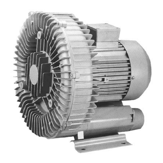
- Page 1 OPERATION/MAINTENANCE INSTRUCTIONS REGENERATIVE BLOWER Registered and approved by one or more of these standards agency RoHS 9001 Compliant All-Star Series and BigBertha Blower Are registered trade marks of All-StarProducts.
- Page 2 Sample Installation Layout Pressure Typical Pressure Pressure ReliefValve Gauge Arrangement Vent Check Line Valve 3 pipe diameters 3 pipe diameters System Pressure +/-1 diameter +/-1 diameter Discharge Blower Inlet Vacuum Min 5pipe Min 2pipe Filter diameters Diameters from Inlet or flowmeter Inlet Filter Flow Meter 1.
- Page 3 “A”. If mounting position “B” is desired, the extra mounting parts can be discarded. Should you have any questions regarding this conversion, feel free to contact All-Star Products at 800-431-8258. DISCHARGE POSITION “A” DISCHARGE POSITION “B”...
- Page 4 Environment (Ambient) Temperature The blower motor rating is based on an ambient temperature of 40 Deg C (104 Deg F). For operation in higher temperature ambients, refer to All-Star Products.
- Page 5 forma nce Spec ific ations All blower motors are 2 pole design and operate at approximately 3450 rpm on 60Hz and 2850 rpm on 50Hz. Motors are suitable for operation on 50Hz at 3/50/220/380 volts. Motor rated current can vary from the table below. It is recommended to use the name plated current values in those cases.
-
Page 6: Operation
OPERATION Transport and Storage When lifted by crane, All-Star blowers must be secured at the eyebolt on the pump casing Attention should be paid to the load bearing capacity of the hoisting equipment (refer to Table 1 for unit weight). Installation All-Star blowers can be installed and mounted in any horizontal or vertical position. -
Page 7: Electrical Connection
The flow noise is reduced by the built-in silencers. In the case of free-gas intake or exhaust, the noise can be further reduced by attaching silencers to the blower. In order to reduce the noise emissions further, the blowers should not be attached onto components that radiate sound, such as thin-walled structural steel or metal plates. - Page 8 Commissioning CAUTION The blower must not be operated with the Intake or outlet closed or blocked. CAUTION If the blower is started without being bolted to a mounting base, the initial starting torque of the motor will cause the blower to move suddenly and possibly topple over.
-
Page 9: Bearing Types
Lubrication DANGER Before any work is performed on the blower, equipment and especially when removing covers on moving parts, the motor is to be disconnected from electrical power. DANGER Do not connect electrical power supply until the blower and other equipment are completely re-assembled. Disassembly Blower models RB8 series and larger and all 2-stage blowers have an external grease fitting for the blower end bearing. - Page 10 TABLE 3.4 Bearing Types, Sizes and Lubricantion Impeller Motor Side Fan End Type Type Deg F Model Deg F Bearing Bearing 6202zz 6201zz RB1 Series Shield Shield RBH2 Series 6203zz Shield 6202zz Shield 6204z Shield Shield 6204zz RBH3 Series 6205zz...
-
Page 11: Maintenance
Covers which prevent contact with rotating parts DANGER are not to be opened during operation. MAINTENANCE DANGER Before any work is performaned on the blower, equipment and especially when removing covers on moving parts, the motor needs to be disconnected from the electrical power supply. -
Page 12: Troubleshooting
Troubleshooting Problem Cause CorrectiveSteps At least two power Eliminatei nterruption by Motor does not start, Supply conductors Means of fuses, No rotor noise. interrupted Terminals or lead feeder. Interruption in one power See"Motor does not start, Motor does not start, Supply conductor No running noise."... - Page 13 SingleStageSampleAssembly -12-...
- Page 14 5.1 Two Stage Sample Assembly -13-...
- Page 16 Thermal Overload Connection Diagrams Thermal protectors are supplied loose as standard in all single phase motors. If you choose to wire the thermal protector into your power circuit, you need to follow the instructions below. Depending on the blower model, the thermal protector can be wired to operate in either an automatic or pilot duty mode only.
- Page 17 A disassembled unit will not be considered as a warranted failure under any circumstances. For more detailed information, visit http://www.all-star-usa.com All-Star Products Inc Sales Office & National Warehouse 2095 Exeter Rd Ste 80-324 Memphis TN 38138 Tel 800-431-8258 Tel 901-755-9613 Fax 901-758-0816 service@all-star-usa.com...
Need help?
Do you have a question about the RB1 Series and is the answer not in the manual?
Questions and answers