Table of Contents
Advertisement
Quick Links
Advertisement
Table of Contents

Related Manuals for iGUIDE IMS-5

Summary of Contents for iGUIDE IMS-5
- Page 1 I MS-5 C amera System System and Software Documentation Revision 1.22 ...
-
Page 2: Table Of Contents
IMS-5 Camera System: ® System and Software Documentation Table of contents Regulatory Information Camera System Overview Camera System Components Camera Handling Tripod Setup Connecting to Camera Collecting Data With Survey Create a Project and Floor Turn Laser ON... - Page 3 Compass Calibration USB Flash Drive Factory Reset Firmware Update Troubleshooting Wi-Fi connectivity Survey browser compatibility Removing reflections in mirrors Ball head drift Miscellaneous Survey issues Wrong camera rotation direction Battery Charging Specifications Canon EOS Rebel T100 Menu Settings...
-
Page 4: Regulatory Information
Regulatory Information This product has been tested and was found to comply with the following standards: · FCC PART 15, SUBPART B, Class B - Unintentional Radiators. · Industry Canada ICES-003, Issue 6, Class B - Information Technology Equipment. · CISPR 11:2009 + A1:2010 / EN 55011:2009 +A1:2010, Class B - Industrial, Scientific and Medical Equipment. -
Page 5: Camera System Overview
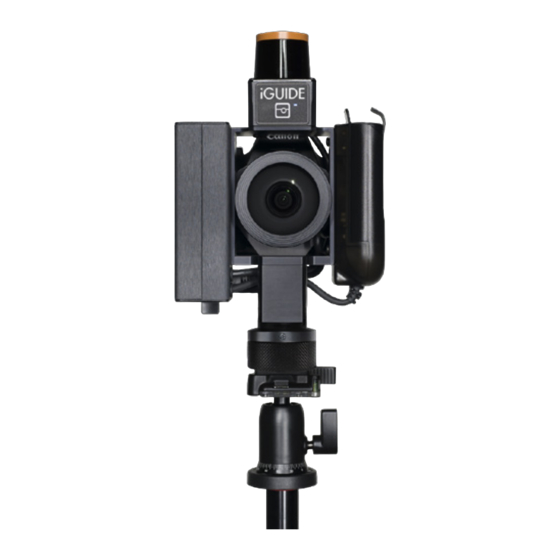
Camera System Overview The iGUIDE Camera System is a unique camera system that measures a space while simultaneously photographing it. Figure 1 shows the main components of the camera system. The camera system uses a l aser scanner for gathering laser measurement data and a D SLR camera with a f isheye lens for shooting ultra wide-angle HDR images that are later stitched into 360-degree panoramas. -
Page 6: Camera System Components
Camera System Components The s ystem controller is the black box on the side of the camera system. On top you will find the power button used to turn the system on. The s ystem battery is located on the side of the camera directly opposite the system controller. It doesn’t need to be removed to be charged and has a charge level indicator on top of the battery itself. -
Page 7: Camera Handling
Camera Handling The camera should be handled by the panoramic rotator and can be additionally supported by a grip onto the system controller. For lens cleaning, the camera can be placed on a table with the fisheye lens facing up and the DSLR camera LCD screen facing down, see Figure 2. The system battery and the DSLR camera battery must be charged before the first use. - Page 8 It is recommended to extend the tripod column at least 10cm (4") to provide enough space for a convenient hand grip, see Figure 3. Raising the column higher will result in too much sway of the camera under its weight when the camera is rotated and will negatively affect quality of panorama alignment and stitching.
-
Page 9: Connecting To Camera
Connecting to Camera The camera is powered on and off by the power button located the top of the system controller. The camera boots in less than 10 seconds, so there is no Sleep mode. After the power LED turns green, navigate to your phone or tablet Wi-Fi settings and connect to the Access Point named planitar-xxxxxx, where xxxxxx is a unique code for each camera. -
Page 10: Collecting Data With Survey
Collecting Data With Survey The Survey user interface is shown in Figure 4. T here are five tabs: Survey, Pano, Floor, Project, and Manage. Each tab represents a separate screen and functions that can be returned to at any time. -
Page 11: Create A Project And Floor
The Stitch application allows manual adjustments to panorama alignment and color, as well as fine-tuning of room positions and floor layout before the iGUIDE data is exported and is ready for upload to the online iGUIDE Portal. Planitar processes the uploaded data to create floor plans from measured data and assemble panoramas and floor plans into a complete iGUIDE. -
Page 12: Shooting Panoramas
If not using the advanced AutoMap mode (described later), ensure the button labeled Mode reads Track. The laser scanner has to be turned on by tapping the button labeled Laser. This must be done prior to capturing any images if measurement data is required. If the laser scanner is not turned on there will be a warning message asking you to do so or proceed with no measurements. -
Page 13: Getting Best Results From Auto Settings
Some panoramas will need to be shot for drafting reference only. They can be selectively disabled in the iGUIDE later if desired. It is possible to shoot only one fisheye image resulting in a partial panorama if it is only needed for reference. In this case you can ignore the warning about incomplete panorama when creating a new panorama after that. - Page 14 You can skip surveying complete floors, such as basements if you do not intend to be showing them in the iGUIDE. Reported Total Interior and Exterior Floor areas for the house will be affected, however. If the Laser is On, each panorama scan will be saved separately from the AutoMap (if using the advanced AutoMap mode explained later) and panorama laser scan data will be shown in blue color.
-
Page 15: Taking Still Pictures
Taking Still Pictures If you want to take a still picture for the iGUIDE image gallery, reposition the camera and tap the Still Image button to take one fisheye image instead of a panorama. You do not need to use the "+1"... -
Page 16: Summary Of Survey Controls And Indicators
Summary of Survey Controls and Indicators System battery indicator shows the system battery charge level and remaining time. The DSLR camera battery indicator shows the remaining charge level in three discrete steps, approximately corresponding to 80%, 50% and 30%. The text in the bottom right corner shows the house, floor, and panorama names. -
Page 17: Summary Of Manage Tab
HDR mode selector. Turn HDR off, select between several HDR bracket presets (Indoor, Outdoor, Beach) or use Custom HDR bracket configurable through the Manage tab. Currently used HDR bracket -/+EV values are shown in the upper right corner of the screen. New panorama location.... - Page 18 The values entered here will affect the custom preset selection found on the Survey tab. Values range from -1 to -7 and +1 to +7.
- Page 19 Safely Remove USB Drive Tapping this button will disconnect the usb drive from the system software. Use this button when removing the usb drive while the camera is running to prevent data loss or corruption. Power Off The camera can be powered off remotely by tapping this button. Calibrate Compass The camera has built in compass that is used for various functions.
-
Page 20: Automatic Mapping Mode (Advanced)
WiFi Password Change the WiFi password used to log into the camera’s WiFi hotspot. WiFi Channel The WiFi channel can be changed to avoid problems when interference is encountered. Acceptable values range from 1 to 11 and Auto. Power Off Timeout Specify the length of time the camera will wait, while inactive, before automatically powering off. -
Page 21: Automatic Mapping Tips
alignment only and is not required for drafting. To use automatic mapping mode follow the steps below: 1. Switch to the Survey tab. 2. Turn the Laser on. 3. Maximize the map view (tap on the resize icon in the upper right corner of the view). 4. -
Page 22: Outdoor And Common Area Scans
If stepping back does not help or if you moved the camera while the laser was off and it lost its position on the map, you can move the scan into correct position manually. Follow these steps. Tap the M ove button under the heading S can . The current scan color will turn yellow. Drag the scan on the screen into place approximately. - Page 23 The scans can also be captured on a separate floor named “Common Areas” or “Exteriors.” This will result in the scans being displayed in the iGUIDE on a separate floor, accessible from the floor selector, that has thumbnails instead of a floor plan for navigation.
-
Page 24: Processing Data With Stitch
360-degree panoramas in two formats – six cubic tiles (always used) and photo spheres (optional). The iGUIDE viewer uses cubic panoramas composed of six square images as the six sides of a cube (cubic tiles) with the view point being at the center of the cube. The cubic panoramas are the most compatible way to display 360-degree images on a wide range of computing devices including mobile phones. -
Page 25: Stitch Workflow
8. Check that panoramas are properly aligned and the verticals are vertical. 9. Adjust panorama colors if desired. 10. H ide panoramas that you do not wish to be shown in the iGUIDE. 11. Review assignment of floors to buildings and wall thickness. - Page 26 The order of floors in the house tree view will determine the order of floors shown in the iGUIDE. The order of scans within each floor determines the order in which scans are visited in iGUIDE Autoplay mode.
-
Page 27: Adding User Panoramas
The initial pano that will appear on iGUIDE load can be set here. An orange dot will appear on the panorama folder indicating that the initial panorama has been set.. - Page 28 It will contain a .tar file with the data to be uploaded to the iGUIDE Portal for drafting the iGUIDE. Move or Rotate Scans. Use this function to drag the active scan to fine-tune its position. A scan can be made active either by selecting it in the project tree view or by holding the Shift key down and clicking on scan points in the main window.
- Page 29 Arrange all panos. All panoramas will be aligned automatically. User input is required to confirm the positions of the data during this process if there are multiple locations where the data might belong. Click Yes to All to skip user input. Arrange selected panos....
- Page 30 Survey app on Manage tab. T ake Snapshots. You can use this tool to snap still pictures for the iGUIDE image gallery from fisheye images. See Figure 10. These pictures will have limited resolution, however. Compose a shot by panning with a mouse.
- Page 31 Figure 10. Stitch Settings. Figure 11. Align Panoramas and Adjust Color.
-
Page 32: Data Quality
Figure 12. Take Snapshots. Data Quality This section will illustrate what is considered good and bad data. Bad data includes insufficient data or data not properly pre-processed for drafting. Planitar drafting team will not be able to draft a property until sufficient data is received and that data is acceptably aligned into correct floor layout. - Page 33 The Ugly data can sometimes be used in drafting, but will have stitching issues in panorama with visible artifacts. Figure 14. Very good and properly aligned data. Planitar drafting team will love you.
- Page 34 Figure 16. Badly positioned and aligned data. Planitar drafting team will not accept this data for drafting until all rooms are positioned on the floor in the correct relationship and are sufficiently aligned. Figure 17. Completely unaligned data. Planitar drafting team will not accept this data for drafting until all panoramas are properly positioned and aligned.
- Page 35 Figure 18. Wrong panorama rotation direction. It must be corrected in Stitch by using the Reverse Camera Rotation option. Figure 19. Missing room data - not all rooms on the floor have image data, so windows and other features cannot be shown properly on the floor plan. Planitar drafting team will not accept this data for drafting.
-
Page 36: Maintenance
Figure 20. Missing data may be easier to see with the coverage mode enabled. Coverage can be visualized in both Survey onsite and in Stitch at home. Maintenance Fisheye Lens Cleaning The fisheye lens should be kept dust-free as dust will appear in images as diffuse circles when shooting against bright objects. -
Page 37: Usb Flash Drive
Reset it is recommended to perform C ompass Calibration . Firmware Update To update system firmware, download a firmware update file f w_update.7z from the iGUIDE Portal Support area. Then follow these steps: E nsure the file is named f w_update.7z... -
Page 38: Troubleshooting
Troubleshooting Wi-Fi connectivity · I f you do not see the camera among available Wi-Fi access points and cannot connect to it, turn Wi-Fi on your smart device off and back on before you try anything else. · I f your connection to camera from Survey seems to timeout, ensure your phone or tablet is still ... -
Page 39: Wrong Camera Rotation Direction
If you run into any issues with Survey, first try re-loading the web app using the Page Reload button from the Survey tab. In case of continued problems, power cycle the camera. When instructed by Planitar, you can save System Log file from the Manage tab and send it to Planitar for further troubleshooting. -
Page 40: Specifications
Specifications Product Name Indoor Mapping System 5 Product Model IMS-5 Performance Measurement range: up to 10m (30ft) Measurement uncertainty: +/- 10mm up to max range (typical, based on at least 60cm wide wall segment) Laser scanner field of view: 270 degrees Lens: 5.6mm, F/5.6, 185 degrees field of view, full circle fisheye... -
Page 41: Canon Eos Rebel T100 Menu Settings
Canon EOS Rebel T100 Menu Settings These are factory settings and should not modified, unless noted. Camera controls Set Mode Dial to M Set ISO to 200. Can set to 100 for sunny locations. Shooting 1 Quality: L 18M Beep: Disable Release shutter without card: Enable Image review: Off Peripheral illumin.
Need help?
Do you have a question about the IMS-5 and is the answer not in the manual?
Questions and answers