Advertisement
MAINTENANCE
Disconnect power source and ensure pressure is removed from pump head prior to
performing any maintenance. Hazardous pressures can result in serious injury or
property damage.
Pump Head Maintenance
Pump Head Assembly (3/16" to 1/2" Plunger Size)
Step 1: Ensure all parts are clean and free from damage (see Inspection section). Lubricate all O-rings
with petroleum based lubricant; lubricate packing and plunger with a Teflon or graphite based packing
lubricant.
Step 7: Install gasket and cover with wing screws. Install and tighten priming valve into body.
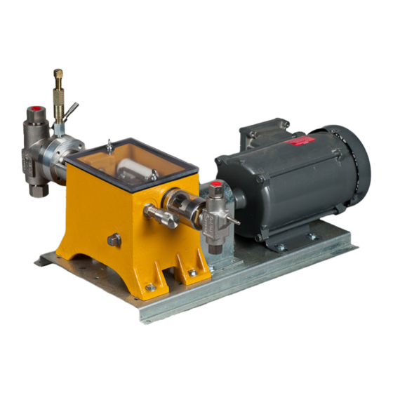
BR4300
Electric Drive Chemical Injection Pump
Step 2: Install O-ring into bottom seat. Place 3/8" ball into bottom seat
(install metal gasket on seat for 3/16" plunger size) and thread seat into
suction end of body utilizing a thread sealant. Tighten bottom seat.
Step 3: Place the 1/4" ball into the discharge end of the body, for plunger
sizes 1/4" to 1/2". Install O-ring into top seat and insert top seat into body.
Place the 3/8" ball and ball check spring into the top bushing. Thread top
bushing into body, utilizing a thread sealant. Tighten top bushing.
Step 4: Install packing in body, ensuring it is installed in the correct order
and orientation. Note: The "V-Ring" point should be pointing outward. Place
plunger packing gland on the packing. Thread yoke lock nut and yoke onto
the body. Loosely thread plunger packing gland nut onto body. Install plunger
wiper ring and yoke packing set into yoke. Insert plunger into yoke and body
ensuring plunger drip ring is installed on plunger.
Step 5: Thread yoke packing nut into yoke finger tight. Install yoke into
housing with Belleville washers in place. Slide plunger into the adjustment
bolt and insert plunger pin.
Step 6: Orientate body in upright position with suction port down and tighten
yoke lock nut. Snugly tighten the plunger packing gland nut, do not over
tighten.
Maintenance
and Inspection
12-19
Advertisement
Table of Contents

Related Manuals for Bruin Pumps BR4300


Summary of Contents for Bruin Pumps BR4300
- Page 1 Maintenance and Inspection BR4300 Electric Drive Chemical Injection Pump MAINTENANCE Disconnect power source and ensure pressure is removed from pump head prior to performing any maintenance. Hazardous pressures can result in serious injury or property damage. Pump Head Maintenance Pump Head Assembly (3/16” to 1/2” Plunger Size) Step 1: Ensure all parts are clean and free from damage (see Inspection section).
- Page 2 Pump Head Disassembly (3/16" to 1/2” Plunger Size) Step 1: Disconnect power source, ensure all pressure is removed from pump head assembly and isolate fluid discharge and suction lines. Open and remove priming valve. Disconnect fluid discharge and suction lines. Step 2: Remove cover and gasket by loosening and removing wing screws.
- Page 3 Step 7: Orientate body in upright position with suction port down. Snugly tighten plunger packing gland nut, do not over tighten. Step 8: Install gasket and cover with wing screws. Install and tighten priming valve into body. Pump Head Disassembly (3/4" and 1” Plunger Size) Step 1: Disconnect power source, ensure all pressure is removed from pump head assembly and isolate fluid discharge and suction lines.
- Page 4 Step 5: Insert cap screw with lockwasher and bottom thrust washer into worm gear. Thread cap with O-ring onto lower bearing. Ensure worm gear rotates freely by hand before proceeding. Step 6: Press needle bearing into housing. Step 7: Press inner race bearing and bearing onto worm and shaft assembly. Install snap rings onto worm and shaft assembly on both sides of bearing.
- Page 5 Step 14: Place the O-ring on the stroke adjustment spindle and thread the stroke adjustment knob into the adjustment spindle. Install gasket onto adjustment spindle and thread into housing. Slide stroke adjustment drive gear onto stroke adjustment assembly, ensuring that the gear teeth mesh with the stroke adjustment gear but do not tighten the two set screws on the stroke adjustment drive gear.
- Page 6 Housing Disassembly Step 1: Disconnect power source, ensure all pressure is removed from pump head assembly and isolate fluid discharge and suction lines. Open and remove priming valve. Disconnect fluid discharge and suction lines. Drain oil from gear box. Step 2: Remove wing screws, washer seals, cover and gasket. Step 3: Remove plunger pin.
Need help?
Do you have a question about the BR4300 and is the answer not in the manual?
Questions and answers