Table of Contents
Advertisement
Quick Links
USER´S MANUAL
Instructions for Operation, Maintenance
and Installation
LPG Dispenser for Dispensing of Liquiefied
Propane-butane
V-line 899x.xxx/LPG
Adast Systems, a.s., 679 04 Adamov No. 496, Czech Republic
T +420 516 519 201, F +420 516 519 102, sales@adastsystems.cz
www.adastsystems.cz
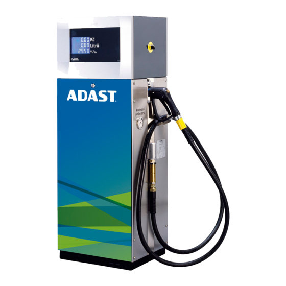
POPULAR LPG
MINOR LPG
OÚ/005/2005/A
XII/2016
Advertisement
Table of Contents

Related Manuals for ADAST POPULAR LPG

Summary of Contents for ADAST POPULAR LPG
- Page 1 Instructions for Operation, Maintenance and Installation LPG Dispenser for Dispensing of Liquiefied Propane-butane POPULAR LPG MINOR LPG V-line 899x.xxx/LPG Adast Systems, a.s., 679 04 Adamov No. 496, Czech Republic OÚ/005/2005/A XII/2016 T +420 516 519 201, F +420 516 519 102, sales@adastsystems.cz www.adastsystems.cz...
-
Page 5: Table Of Contents
4.2.2. Case of the electronic counter – design 2017 (see fig.) ..........4 4.3. Hydraulic system of the LPG fuel dispenser ............... 5 4.3.1. The hydraulic system of the fuel dispenser V-line 899x.xxx/LPG - piston volumetric flow meter ADAST M 406.xxxx ....................... 6 4.4. Electronics ....................... 7 4.5. - Page 6 USER’S MANUAL V-line 899x.xxx/LPG 9.8. Dispensing hose ....................16 9.9. LPG dispensing nozzle ..................16 9.10. Dismantling of covers ..................16 9.11. Maintenance instructions for dispenser body parts ............. 17 9.12. Electronic counter .................... 18 10. DISASSEMBLY AND DISPOSAL ..................18 11.
-
Page 7: Important Notice
USER’S MANUAL V-line 899x.xxx/LPG 1. IMPORTANT NOTICE This document is a guideline for the user how to proceed when installing, attending and maintaining the dispenser. The information included in the present instructions are mandatory and the manufacturer does not accept any responsibility for any damage due to their non-observance. In the complex of the filling station, the dispenser is taken for a component of the dedicated gas equipment subject to checks and revisions in the line of valid regulations anchored in the Filling station operating regulation. -
Page 8: Use
USER’S MANUAL V-line 899x.xxx/LPG 2. USE The liquid fuel dispensers of the V-line 899x.xxx/LPG series with an electronic counter ADP1/L, ADP1/T, ADP2/T L of volume and price, alternatively mechanical counter of volume (for non-public dispensing) described in the present manual have been designed for the dispensing of liquefied propane-butane (LPG). The dispensing is made only by operating staff of the filling station (service mode). -
Page 9: Operation Safety
USER’S MANUAL V-line 899x.xxx/LPG 3.2. Operation safety Responsible for the filling station operation is the keeper who is bound to charge with the station operation the properly trained and authorised personnel only with corresponding qualification. Duty of the operators consists in filling the vehicle LPG pressure tanks in qualified way while respecting all safety regulations, and in checking - in regular intervals - the dispenser and tank for proper conditions, the mechanical equipment for proper run, gas pressure for proper level, and in keeping the prescribed operational records. -
Page 10: Description
4.1. Design of the dispensers The dispensers ADAST POPULAR LPG is produced in two model lines: V-line 899х.ххх/LPG - with a measuring unit ADAST LPG - piston positive displacement flow meter ADAST M 406.xxхх Number of dispensing Type V - line... -
Page 11: Hydraulic System Of The Lpg Fuel Dispenser
USER’S MANUAL V-line 899x.xxx/LPG Above the display is placed IR sensor (5) for controlling and adjusting the dispenser calculator manager or servicing keyboard. On the outer side of the case cover is placed (optional) keyboard local user preferences (4) - an independent keyboard for each dispensing point. -
Page 12: The Hydraulic System Of The Fuel Dispenser V-Line 899X.xxx/Lpg - Piston Volumetric Flow Meter
ME 01-05 or ME 01-05-05 or METRA MTX 075 or ADAST40 Differential valve ADAST V 860.20/LPG Electromagnetic valve Sight glass LPG – ADAST (optionally) Snímač teploty LPG Pt 100 - ZPA Manometer 0/25 bar Ball valve G 1/2― metrological branch In normal operation LPG is always in the liquid phase in the hydraulic system of the LPG dispenser. -
Page 13: Electronics
ME 01-05-05 - type designation M 406.25P, M 403.32EP or with a magnetic pulse transmitter METRA MTX 075 or ADAST 40 - type designation M 406.25P/1, M 406.25EP/1. Meters with the designation of EP in electronic calibration, indicating P mechanical calibration In the hydraulic system of the LPG dispenser during normal operation occurs always LPG in the liquid phase. -
Page 14: Communication To The Control System
USER’S MANUAL V-line 899x.xxx/LPG equipment can be complemented by the ADP1/T, ADP2/T, ADP1/L electronic counter for public dispensing. The fuel dispenser is connected through a communication line to the control system, which controls the operation of the whole filling station (releasing of dispensers, volume preselection, unit price variation, self-diagnosis, etc.). -
Page 15: Identification
6. IDENTIFICATION 6.1. Rating plate of the LPG fuel dispenser V-line 899x.xxx/LPG Measuring device manufacturer and address Adast Systems, a.s., CZ – 679 04 Adamov 496 Name of measuring device LPG dispenser CE marking with the number of the Notified body coopreated in the conformity Assessment and supplementary metrology marking M (xx –... -
Page 16: Filling Of Liquefied Gas Into Motor Vehicles
USER’S MANUAL V-line 899x.xxx/LPG Liquid temperature range – T [°C] –20 to +50 [°C] 10. Mechanical class 11. Electromagnetic class 12. Liquid 13. Maximum flowrate [L/min] 14. Minimum flowrate [L/min] 15. Minimum measured quantity MMQ [L] 16. Maximum pressure [bar] 17. -
Page 17: Self Dispensing
USER’S MANUAL V-line 899x.xxx/LPG 2. Then he checks the connection to the filler of the storage tank which is led to the vehicle surface, the type of the vehicle fuel tank filler and decides either for direct connection of the dispensing nozzle to the filler of for the use of an adapter for different types of vehicle fillers. -
Page 18: Description Of The Preselection Function
USER’S MANUAL V-line 899x.xxx/LPG 7.4. Description of the preselection function The selection of the required value of fuel to be dispensed is carried out with the switch for pump motor start in the position OFF (0)! 1. Connect the dispensing nozzle to the fuelling ending of the vehicle tank. 2.a) Preselect the required quantity to be dispensed according to the price by keys identified 5 and 10 in arbitrary sequence up to the amount of money level. -
Page 19: Manual Setting Of Unit Prices
USER’S MANUAL V-line 899x.xxx/LPG even in case the nozzle has been either hung up again without fuel dispensing or previous transaction has not been deactivated by means of RLS entry. 8.1. Manual setting of unit prices Necessary conditions for the transition to the setting of unit prices –... -
Page 20: Maintenance Of The Dispenser And Its Individual Operating Units
USER’S MANUAL V-line 899x.xxx/LPG 1. Both dispensing points shall be free (transitions are not running at any of the both points and terminated transactions shall be acknowledged). 2. Depress the "+" key to display the volume sum. Depress the "-" key to display the price sum. 3. -
Page 21: Separator
USER’S MANUAL V-line 899x.xxx/LPG counterpressure of gaseous phase as generated by the spring pushing the differential piston into the valve seat from the side of the gaseous phase allows to shift the valve cone of the differential piston off the valve seat so that the flow through the valve is open. -
Page 22: Lpg Sight-Glass
USER’S MANUAL V-line 899x.xxx/LPG 9.7. LPG sight-glass The sight-glass has been designed for the visual checking of the flow of liquefied gas being dispensed. Its design does not require any maintenance. In case of a mechanical defect only a specialist of the service shop can repair it. -
Page 23: Maintenance Instructions For Dispenser Body Parts
USER’S MANUAL V-line 899x.xxx/LPG Dismount the covers, unscrew the bolts connecting the meter to the joining piece. Disconnect the flange connection to electromagnetic valve, dismount the bolts of the integrated detector and remove it from the meter. Reverse procedure is used for remounting the meter. Dismantling of the electromagnetic valve Disassemble the covers of hydraulics, disconnect the joining tube by means of a cap nut. -
Page 24: Electronic Counter
USER’S MANUAL V-line 899x.xxx/LPG 9.12. Electronic counter No maintenance of the electronic counter is performed. Any manipulation with the counter and wiring of the dispenser can be only performed by a qualified person. The electronic counter itself is repaired by replacement at the filling station. DISASSEMBLY AND DISPOSAL ATTENTION! Considering the fact that the residues of fuel always are left in hydraulic distributing systems and in... -
Page 25: Transport
The customer shall agree to the method of dispenser transport from the manufacturer in the contract. In case Adast Systems, a.s. provides the transport for the customer, the product will be delivered to the agreed destination. The manufacturer possesses the necessary knowledge of handling and transportation methods. -
Page 26: Wiring
USER’S MANUAL V-line 899x.xxx/LPG The dispenser requires the connection to the return DN 16 piping. The separator return piping involves a metrological branch provided with a G ½ ‖ spherical cock designed to metrological verification of the dispenser and the servicing purposes. The return piping of DN 16 connected to the storage tank is jointed to the G 1/2"... -
Page 27: Putting Of The Dispenser Into Operation
USER’S MANUAL V-line 899x.xxx/LPG PUTTING OF THE DISPENSER INTO OPERATION Entire hydraulic system of the LPG module has to be subjected to the pressure test by nitrogen of 2,5 MPa pressure. Being the test pressure attained, check all joints of the hydraulic system by a foaming agent. Wiring inspection of the dispenser unit has to be carried out. -
Page 28: Spare Parts Catalogue
USER’S MANUAL V-line 899x.xxx/LPG Defects and deficiencies resulting from the incorrect or careless servising, revision and maintenance of the dispenser and of its various functional units are not subject of guarantee and, therefore, the reclamations of this kind will be never admitted. In the course of operation, the liquefied gas storage tanks have to be checked and water and other impurities have to be removed. - Page 29 ADAST 40 to the electronic counter ADP1 - connector X1 Connection of the magnetic pulse transmitter ME 01-05, MTX 075 and Enclosure No. 18 ADAST 40 to the electronic counter ADP1/T, ADP2/T - connector X2 Enclosure No. 19 Hazard zones of dispensers V-line 899x.xxx/LPG series Enclosure No.
- Page 31 USER’S MANUAL V-line 899x.xxx/LPG Main dimensions of dispensers V-line popular 899x.xxx/LPG Enclosure No.
- Page 32 USER’S MANUAL V-line 899x.xxx/LPG Main dimensions of dispensers V-line minor 899x.xxx/LPG Min. distances of the dispenser from a steady obstacle located at the filling station Enclosure No. 2...
- Page 33 USER’S MANUAL V-line 899x.xxx/LPG View of dispensers V-line 8991.6x2/LPG series View of dispensers V-line 891x.6x3/LPG series Enclosure No.
- Page 34 USER’S MANUAL V-line 899x.xxx/LPG View of dispensers V-line 8992.6x2/LPG series View of dispensers V-line 8995.6x2/LPG series Enclosure No. 4...
- Page 35 USER’S MANUAL V-line 899x.xxx/LPG Installation dimensions of V-line 8991.xxx/LPG and V-line 8995.xxx/LPG dispensers Enclosure No.
- Page 36 USER’S MANUAL V-line 899x.xxx/LPG Installation dimensions of V-line 8994.xxx/LPG and V-line 8994.xxx/LPG dispensers Enclosure No. 6...
- Page 37 USER’S MANUAL V-line 899x.xxx/LPG Installation dimensions of V-line 8991.6x3/LPG Enclosure No.
- Page 38 USER’S MANUAL V-line 899x.xxx/LPG Areas with risk of gas pressure release or residual nitrogen at the separator used in the hydraulic circuit of V-line 899x.xxx/LPG dispensers Enclosure No. 8...
- Page 39 USER’S MANUAL V-line 899x.xxx/LPG Conditions of wiring and operation of UPS for feeding a control system and electronic part of V-line dispensers 1. All the cooperating electronic circuits of the control system and dispensers must be connected to the UPS and for this point of view they are considered as a closed electronic unit.
- Page 40 USER’S MANUAL V-line 899x.xxx/LPG Connection of the fuel dispenser V-line 8991.xxx/LPG, V-line 8993.xxx/LPG and V-line 8995.xxx/LPG to the filling station switchboard Enclosure No. 10...
- Page 41 USER’S MANUAL V-line 899x.xxx/LPG Connection of the fuel dispenser V-line 8992.xxx/LPG and V-line 8994.xxx/LPG to the filling station switchboard Enclosure No.
- Page 42 USER’S MANUAL V-line 899x.xxx/LPG Connection of the fuel dispenser V-line 8991.xx3/LPG with ADP1/L counter to the filling station switchboard Enclosure No. 12...
- Page 43 USER’S MANUAL V-line 899x.xxx/LPG Connection of the fuel dispenser V-line 8991.xx3/LPG with ADP1/T counter to the filling station switchboard Enclosure No.
- Page 44 USER’S MANUAL V-line 899x.xxx/LPG Connection of V-line 8991.623/LPG dispenser without the conduit box to the filling station switchboard Enclosure No. 14...
- Page 45 USER’S MANUAL V-line 899x.xxx/LPG Connection of the fuel dispenser V-line 8991.6x4/LPG with mechanical counter to the filling station switchboard Enclosure No.
- Page 46 USER’S MANUAL V-line 899x.xxx/LPG Connection of the fuel dispenser heating to the filling station switchboard (valid only for the fuel dispenser with electronic case heating) Enclosure No. 16...
- Page 47 USER’S MANUAL V-line 899x.xxx/LPG Connection of the magnetic pulse transmitter ME 01-05, ME 01-05-05, MTX 075 and ADAST 40 to the electronic counter ADP1/L - connector X1 Magnetic pulse Magnetic pulse Magnetic pulse Magnetic pulse transmitter ME 01-05 transmitter ME-01-05-05...
- Page 48 USER’S MANUAL V-line 899x.xxx/LPG Connection of the magnetic pulse transmitter ME 01-05, ME 01-05-05, MTX 075 and ADAST 40 to the electronic counter ADP1/T, ADP2/T - connector X2 Enclosure No. 18...
- Page 49 USER’S MANUAL V-line 899x.xxx/LPG Hazardous zones of LPG dispensers V-line 899x.xxx/LPG series Hazardous zones both inside and outside the fuel dispenser have been defined according to EN 14678-1+ A1. LPG dispenser V-line 899x.6х2/LPG: The inner space of the LPG dispenser hydraulic housing – ZONE 1. The inner space of the LPG dispenser column –...
- Page 50 USER’S MANUAL V-line 899x.xxx/LPG Hazardous zones of LPG dispensers V-line 899х.6х2/LPG Hazardous zones of LPG dispensers V-line 8991.6х2/LPG, V-line 8995.6х2/LPG Hazardous zones of LPG dispensers V-line 8993.6х2/LPG, V-line 8994.6х2/LPG, V-line 8992.6х2/LPG Enclosure No. 20...
- Page 51 USER’S MANUAL V-line 899x.xxx/LPG Hazardous zones of LPG dispensers V-line 899х.6х3/LPG Hazardous zones of LPG dispensers V-line 8991.6х3/LPG Enclosure No.
- Page 52 USER’S MANUAL V-line 899x.xxx/LPG Type marking on the dispenser rating plate – V-line 899x.xxx/LPG Enclosure No. 22...
- Page 53 USER’S MANUAL V-line 899x.xxx/LPG Type marking on the dispenser rating plate – V-line 899x.xxx/LPG/CA Enclosure No.
Need help?
Do you have a question about the POPULAR LPG and is the answer not in the manual?
Questions and answers