Table of Contents
Advertisement
Quick Links
USER´S MANUAL
Instructions for Operation, Maintenance
and Installation
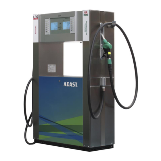
Combined dispenser
for dispensing classic and alternative
liquid fuels and liquefied
propane-butane
V-line 899x.xxx/LPG HYBRID
Adast Systems, a.s., 679 04 Adamov No. 496, Czech Republic
T +420 516 519 201, F +420 516 519 102, sales@adastsystems.cz
www.adastsystems.cz
MKT-001-01-2011/MSS/A
XI/2017
Advertisement
Table of Contents

Related Manuals for ADAST V-line 899 LPG HYBRID Series

Summary of Contents for ADAST V-line 899 LPG HYBRID Series
- Page 1 Installation Combined dispenser for dispensing classic and alternative liquid fuels and liquefied propane-butane V-line 899x.xxx/LPG HYBRID MKT-001-01-2011/MSS/A Adast Systems, a.s., 679 04 Adamov No. 496, Czech Republic T +420 516 519 201, F +420 516 519 102, sales@adastsystems.cz XI/2017 www.adastsystems.cz...
-
Page 3: Table Of Contents
The integrated hydraulic unit for petrol or diesel ............8 4.3.1. The hydraulic system of the fuel dispenser V-line 899x.xxx/LPG - piston volumetric flow meter ADAST M 406.xxxx: ..............12 4.3.2. The hydraulic system of the fuel dispenser V-line 899x.xxx/S/LPG HYBRID with a mass flow meter ................ - Page 4 USER’S MANUAL V-line 899x.xxx/LPG HYBRID 7.1.2. Description of the preselection function ........... 33 DISPENSER OPERATION – LPG ..................33 8.1. Attendance ....................33 8.2. Dispensing with service ..................34 8.3. Self dispensing ....................34 8.4. Dispensing with preselection ................35 8.5.
- Page 5 USER’S MANUAL V-line 899x.xxx/LPG HYBRID 13.6. Rupture coupling ....................43 13.7. LPG sight-glass ....................43 13.8. Dispensing hose ....................43 13.9. LPG dispensing nozzle ..................44 13.10. Dismantling of covers ..................44 13.10.1. Covering of duplex hydraulic modules ............44 13.10.2.
- Page 6 USER’S MANUAL V-line 899x.xxx/LPG HYBRID 21. SPARE PARTS CATALOGUE ..................56 22. ACCESSORIES ......................56 23. DOCUMENTATION DELIVERED ..................56 24. ENCLOSURES ......................56...
-
Page 7: Important Notice
USER’S MANUAL V-line 899x.xxx/LPG HYBRID IMPORTANT NOTICE The instructions for attendance, maintenance and installation serve the user to gain information on the design, correct attendance, maintenance and safe installation. The information included in the present instructions are mandatory and the manufacturer does not accept any responsibility for any damage due to their non-observance. -
Page 8: Use
USER’S MANUAL V-line 899x.xxx/LPG HYBRID o) The servicing interventions should be entrusted to the properly trained personnel of the service firm only. p) When fuels are pumped, basic hygienical precautions shall be adhered. The owner shall enable the customer to use protective gloves. SAVE FOR FUTHER USE! Combined fuel dispensers type series V-line 899x.xxx/LPG HYBRID with electronic counter used for the dispensing of liquid petroleum products - automotive petrol, diesel, kerosene, etc., of... -
Page 9: Operation Safety
USER’S MANUAL V-line 899x.xxx/LPG HYBRID Regular inspection of production quality assurance according to Annexes IV and VII of the Directive 94/9/EC executes FTZÚ, s.p., Ostrava – Radvanice, Notified body no. 1026. Notification of quality assurance: No. FTZÚ 02 ATEX Q 020. Considering legal metrology the dispensers have been EC –... - Page 10 (installation and operation of fuel dispensers). Fuel dispensers ADAST V-line 899x.xxx for dispensing of petrol are equipped with an efficient recovery system (reverse exhaust vapor) that meets the requirements of the "Directive 2009/126/EC of the European Parliament and Council”: Volumetric efficiency of vapor recovery...
-
Page 11: Lpg Delivery Module
USER’S MANUAL V-line 899x.xxx/LPG HYBRID 3.3.2. LPG delivery module A gas leakage detector can be located in the dispenser module area (optional - not a part of the standard delivery) which is connected to the evaluating unit signalling leakage in case of a small leakage (low concentration) and putting the filling system out of operation in case of higher concentration. - Page 12 Sight glass ADAST, ELAFLEX Reducer Transit socket Safety socket Spring Spring Dispensing hose LPG ADAST, ELAFLEX, SEMPERIT Dispensing nozzle LPG OPW-BREVETTI NETTUNO, HEFA, STÄUBLI, ELAFLEX, LPG GROUP Breakage coupling ADAST or rupture coupling ELAFLEX, OPW, LPG GROUP Immediate piece Immediate piece...
-
Page 13: Skeleton
USER’S MANUAL V-line 899x.xxx/LPG HYBRID Dispensing nozzle for Dispensing nozzle petrol or diesel for LPG 4.1. Skeleton Skeleton – a self-supporting structure consisting of parts with high anticorrosive resistance. The base of the dispenser is made of steel sheet, zinc-coated and varnished. Internal parts of the skeleton are made of galvanised sheet. -
Page 14: The Integrated Hydraulic Unit For Petrol Or Diesel
Four-piston all-aluminium meter and an integrated magnetic pulse transmitter ADAST M 403.25P, M 403.32P, M 403.25EP, M 403.32EP, 403.25P/1, M 403.32P/1, M 403.25EP/1, M 403.32EP/1 Magnetic pulse transmitter ADAST 40 or ELTOMATIC ME 01-05 nebo ME 01-05-05, METRA MTX 075 Electromagnetic valve... - Page 15 USER’S MANUAL V-line 899x.xxx/LPG HYBRID The integrated hydraulic unit consists of a pumping monoblok (pos. 1) with an integrated large-surface filter (pos. 2), a meter (pos. 3) with integrated magnetic pulse transmitter (pos. 4) connected with the pumping monoblok (pos. 1) through a special joining piece (pos. 8) and a driving el. motor (pos. 13) of the pump.
- Page 16 Meters are supplied with optional integrated magnetic pulse transmitter or Eltomatic ME 01-05 nebo ME 01-05-05 - type designation M 403.25P, M 403.32P, M 403.25EP, M 403.32EP or with a magnetic pulse transmitter METRA MTX 075 or ADAST 40 - type designation M 403.25P/1, M 403.32P/1, M 403.25EP/1, M 403.32EP/1.
- Page 17 USER’S MANUAL V-line 899x.xxx/LPG HYBRID 4.3. Hydraulic system of the LPG Separator Supply piping Return piping Poition Hydraulics components LPG Ball valve – supply pipe Filter Return valve liquid phase Pressure release valve of the gas phase Safety valve of gaseous phase Hole in the safety valve LPG measurement unit (optional volume or mass) Differential valve...
-
Page 18: The Hydraulic System Of The Fuel Dispenser V-Line 899X.xxx/Lpg - Piston Volumetric
05 or ME 01-05-05 or METRA MTX 075 or ADAST40 Differential valve ADAST V 860.20/LPG Electromagnetic valve Sight glass LPG – ADAST (optionally) Snímač teploty LPG Pt 100 - ZPA Manometer 0/25 bar Ball valve G 1/2― metrological branch In normal operation LPG is always in the liquid phase in the hydraulic system of the LPG dispenser. -
Page 19: The Hydraulic System Of The Fuel Dispenser V-Line 899X.xxx/S/Lpg Hybrid With A Mass Flow Meter
01-05-05 - type designation M 406.25P, M 403.32EP or with a magnetic pulse transmitter METRA MTX 075 or ADAST 40 - type designation M 406.25P/1, M 406.25EP/1. Meters with the designation of EP in electronic calibration, indicating P mechanical calibration. -
Page 20: Elektronics
USER’S MANUAL V-line 899x.xxx/LPG HYBRID Differential valve ADAST V 860.20/LPG Electromagnetic valve Sight glass LPG – ADAST (optionally) Manometer 0/25 bar Coupling safety (breaking or rupture coupling) Ball valve G 1/2― metrological branch Meter LPG – mass flowmeter Micro Motion ® F-Series (Coriolis Flow and Density Meters) nebo Еndress + Hauser –... -
Page 21: Communication To The Control System
4.5. Vapour recovery system Fuel dispensers ADAST POPULAR type line V-line 899x.xxx are supplied in the following modifications of petrol vapor recovery systems : System VRC-M Vapour Recovery Control – Mechanical - control the flow of vapor by hydromechanical proportional valve integrated into nozzle (Elaflex). -
Page 22: Description Of Vapour Recovery System
(dispensing areas), if the fault is not rectified within seven days. 4.5.1. Description of vapour recovery system Pic.1 ADAST MINOR V-line 8991.623 ADAST POPULAR V-line 8991.423 ADAST POPULAR V-line 8995.423 Pos. 7 – vapour recovery system 4.5.2. - Page 23 USER’S MANUAL V-line 899x.xxx/LPG HYBRID Position Unit name Flexible pipe with union nut M 16 x 1,5 for connection to outgoing pipe into storage tank. Piston vacuum pump Flexible connecting pipe between the vacuum pump and coaxial interpiece Coaxial interpiece for connecting of coaxial delivery hose Coaxial delivery hose Delivery nozzle for vapour recovery with integrated hydromechanical proportional valve (ELAFLEX GRVP)
-
Page 24: System Vrc-E
USER’S MANUAL V-line 899x.xxx/LPG HYBRID 4.5.3. System VRC-E Vapour Recovery Control - Electronic - control the flow of vapor through the proportional solenoid valve controlled electronic counter dispenser. Vapour recovery system VRC-E of fuel dispensers V-line 899x.xxx consists of the following basic components (structural layout and design is evident from Figure 1, 2: Position Unit name... -
Page 25: System Vrc-M With Vrms
USER’S MANUAL V-line 899x.xxx/LPG HYBRID Proper function of vapor recovery is indicated by shining symbol of two arrows (Fig. 9) on the display of electronic counter on the appropriate side of the dispenser. Pic. 3 Pic. 4 System VRC non functional System VRC is functional 4.5.4. - Page 26 USER’S MANUAL V-line 899x.xxx/LPG HYBRID Pic. 6 Pic. 7...
- Page 27 USER’S MANUAL V-line 899x.xxx/LPG HYBRID Electronic connection of unit VAPORIX-Control Terminal block for connection of measuring probe VAPORIX-Flow Terminal block for connection of input power Output – communication line for connecting of unit VAPORIX Master Pulse inlet from the module VAP of electronic counter Out A(B) 1 –...
-
Page 28: System Vrc-E With Vrms
USER’S MANUAL V-line 899x.xxx/LPG HYBRID Obr. 9 4.5.5. System VRC-E with VRMS Vapour Recovery Control - Mechanical - flow control vapor through hydromechanical proportional valve integrated into nozzle (ELAFLEX) controlled system VRMS (Vapor Recovery Monitoring System). VRC-M Systems and VRMS working separately (independently). Complete system VRC-E + VRMS contains following components (as pic. - Page 29 USER’S MANUAL V-line 899x.xxx/LPG HYBRID Pic. 15 Pic. 16...
- Page 30 USER’S MANUAL V-line 899x.xxx/LPG HYBRID Pic. 10 Scheme of inputs and outlets of the unit VAPORIX-Control...
-
Page 31: Function Of System Vrc With Vrms
USER’S MANUAL V-line 899x.xxx/LPG HYBRID 4.5.6. Function of system VRC with VRMS Function of system VRC-M with VRMS Function of system VRC-M The vacuum in the VRC-M system is created plunger vacuum pump (Item 2), which is powered via a rubber belt electric pumping monoblock. -
Page 32: Indication Of System Status Vrms
USER’S MANUAL V-line 899x.xxx/LPG HYBRID Optimal flow of vapor is dynamically regulated by the proportional hydromechanical valve depending on the actual flow of liquid petrol trought delivery nozzle. Proper function of vapor recovery is indicated by shining symbol of two arrows (Fig. 9) on the display of electronic counter on the appropriate side of the dispenser. - Page 33 USER’S MANUAL V-line 899x.xxx/LPG HYBRID Pic. 11 2. System VRC works out of settled tolerance – first transaction out of the tolerance System status indication on unit VRMS VAPORIX-Control: In the case, that compared values of realised transaction does not match – it means that declinations of real volume flow measured by system VAPORIX from the set value on proportional vapour recovery valve are not in range from 85 % to 115 % exhausted petrol vapours of delivered liquid petrol from the last transaction –...
-
Page 34: Signalling Of Dispenser Conditions (So)
USER’S MANUAL V-line 899x.xxx/LPG HYBRID Pic. 13 The fault in the revelant system must be fixed by specialised service worker within a period of 7 days (168 hod). 4. VRC system works out of setled tolerance – permanent fault mode – after expire of 7- days time period (168 hours) In the event that the fault of system VRC is not fixed by spealised service worker within a period of 7-days (168 hours) , the functionality of the fuel dispenser will be permanently... -
Page 35: Sopa Design
USER’S MANUAL V-line 899x.xxx/LPG HYBRID 4.7. SOPA design On Client’s special request the dispenser in service mode can be equipped with magnetic release switch (SOPA design). The operator of the filling station can release the dispenser for single filling operation in this mode. - Page 36 USER’S MANUAL V-line 899x.xxx/LPG HYBRID El. motor power supply 3/PE AC 3x 230/400 V ±15 %, 50 Hz Output of pump el. motor 0,55 kW, 0,75 kW, 1,1 kW Output of vacuum pump el. motor 0,18 kW, 0,37 kW Power supply of electronics 1/N/PE AC 230 V ±15 %, 50 Hz příkon 85 VA Power supply of electronic case...
-
Page 37: Identification
All manufactured and delivered dispensers are provided with a rating plate, which includes the following data and is located on a visible point of the dispenser body: Measuring device manufacturer and address Adast Systems, a.s., CZ – 679 04 Adamov 496 Name of measuring device Fuel and LPG dispenser... -
Page 38: Dispenser Operation - Petrol And Diesel
USER’S MANUAL V-line 899x.xxx/LPG HYBRID I: 0,3 – 1 mPa.s II: 1,1 – 8 mPa.s 12.1 Viscosity class III: 8,1 – 17 mPa.s IV: 17,1 – 1000 mPa.s 13.1 Maximum flowrate [L/min] 14.1 Minimum flowrate [L/min] 15.1 Minimum measured quantity MMQ [L] 16.1 Maximum pressure [bar]... -
Page 39: Dispensing With Preselection
USER’S MANUAL V-line 899x.xxx/LPG HYBRID filling is over.předvolené hodnoty. Zákazník může kdykoliv ukončit výdej uvolněním páky výdejní pistole ještě před načerpáním navoleného množství. Po skončení čerpání výdejní pistoli vyjmout z hrdla nádrže a zavěsit do krytu pistole. Preselection keyboard is also equipped with a key with a symbol of a truck, which enables to change the filling rate (it is possible to use only when the fuel dispenseer is equipped with the proportional valve) at the Diesel MIN/MAX dispensing point. -
Page 40: Dispensing With Service
USER’S MANUAL V-line 899x.xxx/LPG HYBRID Controlling of the dispenser V-line 899x.xxx/LPG, V-line 899x.xxx/LPG/М STOP switch Switch Control Button – „SAFETY KEY DEAD MAN― 8.2. Dispensing with service 1. The operator controls the movement of vehicles within the liquefied gas filling area so that the dispensing hose reaches the fuel tank filler of the vehicle. -
Page 41: Dispensing With Preselection
USER’S MANUAL V-line 899x.xxx/LPG HYBRID 2. After connecting the dispensing nozzle to the vehicle filler the operator shall check the connection and then pressing the button (3) resets the counter automatically. After resetting the pump motor is started. The filling can be stopped at any time by releasing the button (3). 3. -
Page 42: Functions Of Kl-Maninf Manager And Kl-Serinf Service Keyboards
USER’S MANUAL V-line 899x.xxx/LPG HYBRID IMPORTANT WARNING: When filling the tank to 80% capacity cut off the mechanical limiter, and regardless of the manual control button or switch. In case the tank is filled to be full (most frequent case) the automatic safety level regulation controlling the filling of the tank to 80 % max. -
Page 43: Setting Of Unit Price Values From The Control System In Auto Mode
USER’S MANUAL V-line 899x.xxx/LPG HYBRID – on the third line of displays the digit, the value of which is being set by the user, is flashing (e.g. on the line of unit price) 3. The user – raises the numerical value of the digit actually set (i.e. the flashing one), (digit 9 passes into 0), by depressing the "+"... -
Page 44: Check Of Vapour Recovery System Function
USER’S MANUAL V-line 899x.xxx/LPG HYBRID 7. The setting of thermal calibration for relevant nozzle is activated by the ATC text. The setting of electronic calibration of the relevant nozzle counter is activated by the EC text. 8. Terminate the scanning by depressing the "0" key and return to the standard mode. 9.4. -
Page 45: Changing The Filter Element
USER’S MANUAL V-line 899x.xxx/LPG HYBRID Possible defects of the monoblock: clogged filter - exchange the filtering sleeve faulty venting, air bubbles appear in the sight glass - it is necessary to check the condition of all sealing parts of the monoblock and complete suction piping ... -
Page 46: Dispensing Nozzle
USER’S MANUAL V-line 899x.xxx/LPG HYBRID 10.6. Dispensing nozzle It is a terminal part of the dispenser by means of which fuels are dispensed. The dispensing nozzle enables: service dispensing - the rate of flow can be controlled up to its full stop by means of control lever –... -
Page 47: Dismounting Of The Electromagnetic Valve
USER’S MANUAL V-line 899x.xxx/LPG HYBRID 10.8.5. Dismounting of the electromagnetic valve Disassemble the covers of hydraulics, disconnect the joining tube by means of a cap nut. Then dismount the fixing bolts of the valve flange. Release the wires of electromagnetic spools in bushings after removing the covers of the hose module. -
Page 48: Maintenance Of The Dispenser And Its Individual Operating Units - Module For Dispensing Lpg
USER’S MANUAL V-line 899x.xxx/LPG HYBRID discharge sediments, water or other contaminants from the tank (containers of fuel) by means of sludge pumps MAINTENANCE OF THE DISPENSER AND ITS INDIVIDUAL OPERATING UNITS – MODULE FOR DISPENSING LPG The user of the dispenser is obliged to operate the device safely, reliably and in economic way. First of all he is obliged to: appoint a worker responsible for the operation and technical conditions of the dispenser and its –... -
Page 49: Electromagnetic Two-Stage Valve
USER’S MANUAL V-line 899x.xxx/LPG HYBRID The cover of the separator filter can be opened when the substance is displaced by nitrogen! Identification of areas exposed to the risk of pressure release of residual nitrogen - see Enclosure No. 10. The safety valve of the gaseous phase in the upper part of the separator (adjusted to 1,8 MPa) prevents the exceeding of the highest working pressure by means of by-passing the liquid phase back to the storage tank. -
Page 50: Lpg Dispensing Nozzle
USER’S MANUAL V-line 899x.xxx/LPG HYBRID ATTENTION! WHEN WOULD BE USED THE NON-CERTIFICATED DISPENSING HOSE, THE EXPLOSION CAN BE INICIATED!!! 13.9. LPG dispensing nozzle The dispensing nozzle for liquefied gas is a final component of the LPG dispensing module. The connecting end of the dispensing nozzle is fitted with a rubber sleeve ensuring tight connection between the dispensing nozzle and the vehicle tank filler. -
Page 51: Maintenance Instructions For Dispenser Body Parts
USER’S MANUAL V-line 899x.xxx/LPG HYBRID 13.11. Maintenance instructions for dispenser body parts Good appearance of dispensers is a part of the filling station standard. Even if the parts of external covering have either been provided with coats of good quality or made of stainless steel, their maintenance should be carried out regularly. -
Page 52: Disassembly And Disposal
USER’S MANUAL V-line 899x.xxx/LPG HYBRID DISASSEMBLY AND DISPOSAL ATTENTION! Considering the fact that the residues of fuel always are left in hydraulic distributing systems and in hydraulic parts of the dispenser it is necessary to pay higher attention to the disassembly and disposal. -
Page 53: Summary Of Principles For Inspection Of Lpg Dispenser
The customer shall agree to the method of dispenser transport from the manufacturer in the contract. In case Adast Systems, a.s. provides the transport for the customer, the product will be delivered to the agreed destination. The manufacturer possesses the necessary knowledge of handling and transportation methods. -
Page 54: Hydraulic Part For Dispensing Petrol And Diesel
USER’S MANUAL V-line 899x.xxx/LPG HYBRID When the dispenser is installed, they shall check the tightness, function of hydraulic equipment of the dispenser, supply piping and fittings. They also check power and communication cables including their lines and fixing. Prior to official metrological testing the dispenser (every dispensing nozzle) has to operate for min. 5 minutes in max. -
Page 55: Installation At The Filling Station With Overground (Aboveground) Tanks
USER’S MANUAL V-line 899x.xxx/LPG HYBRID Greater Pressure system – submersible pump in the tank – than 35 Table 2 – Operating flow rate of the fuel dispenser in relation on the fuel storage tanks parameters for hydraulic unit with Q = 80 dm .min = 130 dm... - Page 56 USER’S MANUAL V-line 899x.xxx/LPG HYBRID check valve prevents permanent supply of stored fuels into the pumping monoblock when the dispenser is out of operation. The pumping monoblock of dispensers (P 640 type) is designed with air separator permanently open to the deaerating chamber formed by the space in the monoblock body and the space of the monoblock cover.
-
Page 57: Mounting Of Spring Of The Spring Hinge
USER’S MANUAL V-line 899x.xxx/LPG HYBRID Fig. 4 Connecting of pipeline output from air separator (OT) in case of connecting fuel dispenser to overground tank. 17.1.3. Mounting of spring of the spring hinge The spring is screwed into the sleeve of the spring hinge lower part on the dispenser column. Then it is secured by tightening the sleeve with the built-in M 6 clamping bolt. -
Page 58: Hydraulic Parts For Dispensing Lpg
USER’S MANUAL V-line 899x.xxx/LPG HYBRID 17.2. Hydraulic parts for dispensing LPG The dispenser can be joined only to process equipment (tanks, piping) of perfect tightness and cleanness. The supplier of the process equipment is responsible for its tightness and cleanness. The dispenser installation is carried out by the organisation authorised by the manufacturer. -
Page 59: Putting Of The Dispenser Into Operation
USER’S MANUAL V-line 899x.xxx/LPG HYBRID Lead-in cables from the switchboard to the dispenser shall answer (number of cores and cross- section) to the specification in enclosures - Connection of dispensers to the switchboard of the filling station. Leads to the dispenser must be sealed to prevent its interior from the penetration of combustible liquids or vapours. -
Page 60: Module For Dispensing Lpg
USER’S MANUAL V-line 899x.xxx/LPG HYBRID – After el. power supply recovery the electronic counter is ready-to-start and fuel filling can continue by lifting the dispensing nozzle. 18.5. Module for dispensing LPG Entire hydraulic system of the LPG module has to be subjected to the pressure test by nitrogen of 2,5 MPa pressure. -
Page 61: Guarantee And Claiming
USER’S MANUAL V-line 899x.xxx/LPG HYBRID GUARANTEE AND CLAIMING Reliable operation and service life of the dispenser depends on correct attendance and maintenance. Therefore it is necessary that every employee maintaining or attending the dispenser is acquainted with all principles of correct attendance and maintenance and related regulations for combustibles handling. Smoking, handling open fire, tanking vehicles with engine running, etc. - Page 62 USER’S MANUAL V-line 899x.xxx/LPG HYBRID SPARE PARTS CATALOGUE Spare parts catalogues of the dispenser are supplied to service organisations. The user can request the spare part catalogues from the manufacturer. ACCESSORIES Parts of the dispenser delivery: Shipping pallet - dismounted at the dispenser shaft site. ...
- Page 63 USER’S MANUAL V-line 899x.xxx/LPG HYBRID Enclosure No. Conditions of wiring and operation of UPS for feeding a control system and electronic part of V–line dispensers Operating conditions of the V-line 899x.xxx/P fuel dispensers (pressure design) Enclosure No. Connection of the fuel V-line 8994.xx2/S/LPG HYBRID, V-line 8996.xx2/S/LPG HYBRID to the filling station switchboard Enclosure No.
- Page 64 USER’S MANUAL V-line 899x.xxx/LPG HYBRID © Adast Systems, a.s., 679 04 Adamov No. 496, Czech Republic Regarding continuous development the producer stipulates the right to pursue technical changes!
- Page 65 USER’S MANUAL V-line 899x.xxx/LPG HYBRID Main dimensions of V-line 899x.4xx/LPG HYBRID dispensers Main dimensions of V-line 899x.6xx/LPG HYBRID dispensers Width of all fuel dispensers is 410 mm Enclosure No. 1...
- Page 66 USER’S MANUAL V-line 899x.xxx/LPG HYBRID Design of the dispenser series V-line 8994.4xx/LPG HYBRID, V-line 8996.4xx/LPG HYBRID Design of the dispenser series V-line 8994.6xx/LPG HYBRID, V-line 8996.6xx/LPG HYBRID Enclosure No. 2...
- Page 67 USER’S MANUAL V-line 899x.xxx/LPG HYBRID View of dispensers V-line 8994.6xx/LPG HYBRID, V-line 8996.6xx/LPG HYBRID Enclosure No. 3...
- Page 68 USER’S MANUAL V-line 899x.xxx/LPG HYBRID Minimum distance betwen the side wal of the fuel dispenser and steady barrier at the location on the filling station Enclosure No. 4...
- Page 69 USER’S MANUAL V-line 899x.xxx/LPG HYBRID Installation dimensions of V-line 899x.xxx/LPG HYBRID Dispensing nozzle for petrol or diesel Dispensing nozzle for LPG Enclosure No. 5...
- Page 70 USER’S MANUAL V-line 899x.xxx/LPG HYBRID Dispensing nozzle for petrol or diesel Dispensing nozzle for LPG LEGENDA: Liquid LPG Supply Line - ISO 228 internal thread - G ¾― Return pipe gaseous phase - internal thread ISO 228 - G ½― Intake of pumped medium - petrol and diesel Vapour recovery Piping Output Cable entry for electrical wiring...
- Page 71 USER’S MANUAL V-line 899x.xxx/LPG HYBRID Connection of V-line 899x.xxx/S/LPG HYBRID – for petrol and diesel, with vapour recovery Connection for Q = 40, 60 dm .min Connection for satelite outlet Connection for Q = 70, 80 dm .min 1 × 40, 60, 80 dm .min Enclosure No.
- Page 72 USER’S MANUAL V-line 899x.xxx/LPG HYBRID Connection of V-line 899x.xxx/P/LPG HYBRID dispensers (petrol and diesel) Connection for Q = 40, 60, 70, 80 dm .min Enclosure No. 8...
- Page 73 USER’S MANUAL V-line 899x.xxx/LPG HYBRID Connection of satellite outlet at the V-line 899x.xxx/LPG HYBRID dispenser (for diesel) Enclosure No. 9...
- Page 74 USER’S MANUAL V-line 899x.xxx/LPG HYBRID Areas with risk of gas pressure release or residual nitrogen at the separator used in the hydraulic circuit of LPG module Enclosure No. 10...
- Page 75 USER’S MANUAL V-line 899x.xxx/LPG HYBRID Dispensing nozzle positions during fuel dispensing (petrol and diesel) Correct position of dispensing nozzle during filling The dispensing nozzle is almost in the horizontal position, the ball does not prevent from air passing, the fuel flows through Incorrect position of dispensing nozzle during filling The dispensing nozzle is diverted from the...
- Page 76 USER’S MANUAL V-line 899x.xxx/LPG HYBRID Conditions of wiring and operation of UPS for feeding a control system and electronic part of V–line dispensers 1. All the cooperating electronic circuits of the control system and dispensers must be connected to the UPS and for this point of view they are considered as a closed electronic unit.
- Page 77 USER’S MANUAL V-line 899x.xxx/LPG HYBRID Connection of the fuel V -line 8994.xx2/S/LPG HYBRID, V-line 8996.xx2/S/LPG HYBRID dispensers to the filling station switchboard Enclosure No. 13...
- Page 78 USER’S MANUAL V-line 899x.xxx/LPG HYBRID Connection of the fuel V-line 8994.xx2/P/LPG HYBRID dispensers with vapour recovery system to the filling station switchboard Enclosure No. 14...
- Page 79 USER’S MANUAL V-line 899x.xxx/LPG HYBRID Connection of V-line 8994.xx2/P/LPG HYBRID, V-line 8996.xx2/P/LPG HYBRID dispensers without vapour recovery system to the filling station switchboard Enclosure No. 15...
- Page 80 USER’S MANUAL V-line 899x.xxx/LPG HYBRID Connection of the fuel dispenser heating to the filling station switchboard (valid only for the fuel dispenser with electronic case heating) Enclosure No. 16...
- Page 81 USER’S MANUAL V-line 899x.xxx/LPG HYBRID Connection of the magnetic pulse transmitter ME 01-05, ME 01-05-05, MTX 075 a ADAST 40 to the electronic counter ADP1/T, ADP2/T - connector X2 Magnetic pulse Magnetic pulse Magnetic pulse Magnetic pulse transmitter ME 01-05...
- Page 82 USER’S MANUAL V-line 899x.xxx/LPG HYBRID A location scheme official marks on the flowmeter M 403.25P for mechanical calibration A location scheme official marks on the flowmeter M 403.25P/1 for mechanical calibration Enclosure No. 18...
- Page 83 USER’S MANUAL V-line 899x.xxx/LPG HYBRID A location scheme official marks on the flowmeter M 403.xxEP for electronic calibration A location scheme official marks on the flowmeter M 403.xxEP/1 for electronic calibration Enclosure No. 19...
- Page 84 USER’S MANUAL V-line 899x.xxx/LPG HYBRID A location scheme official marks on the pumping unit P641.xxx/2/SS A location scheme official marks on the temperature sensor PT 100 Enclosure No. 20...
- Page 85 USER’S MANUAL V-line 899x.xxx/LPG HYBRID A location scheme marks official on the temperature sensor PT 100 – fuel dispenser connected to the central pressure system Enclosure No. 21...
- Page 86 USER’S MANUAL V-line 899x.xxx/LPG HYBRID A location scheme official marks on the flowmeter M 406.25P for mechanical calibration A location scheme official marks on the flowmeter M 406.25P/1 for mechanical calibration Enclosure No. 22...
- Page 87 USER’S MANUAL V-line 899x.xxx/LPG HYBRID A location scheme official marks on the flowmeter M 406.xxEP for electronic calibration A location scheme official marks on the flowmeter M 406.xxEP/1 for electronic calibration Enclosure No. 23...
- Page 88 USER’S MANUAL V-line 899x.xxx/LPG HYBRID A location scheme official marks on the flowmeter ® Micro Motion F-Series for electronic calibration ® Flowmeter Micro Motion F-Series Security barrier – module CNGT A location scheme official marks on the diferencial valve V 860.20/LPG Enclosure No.
- Page 89 USER’S MANUAL V-line 899x.xxx/LPG HYBRID A location scheme official marks on the separator LPG N 821.20/1, N 821.20/1/ATC A location scheme official marks on ADP1/T а ADP2/T calculator Enclosure No. 25...
- Page 90 USER’S MANUAL V-line 899x.xxx/LPG HYBRID A location scheme verification marks on electromagnetic total counter for single-sided fuel dispensers A location scheme verification marks on electromagnetic total counter for multiproduct fuel dispensers Enclosure No. 26...
- Page 91 USER’S MANUAL V-line 899x.xxx/LPG HYBRID A location scheme verification marks on electromagnetic total counter (case version 2017) Enclosure No. 27...
- Page 92 USER’S MANUAL V-line 899x.xxx/LPG HYBRID Hazardous zones of fuel dispensers V-line 899x.4xx/LPG HYBRID Hazardous zones both inside and outside the fuel dispenser have been defined according to EN 13617-1 and EN 14678-1. The inner space of the fuel dispenser hydraulic housing – ZONE 1. The inner space of the fuel dispenser column –...
- Page 93 USER’S MANUAL V-line 899x.xxx/LPG HYBRID Hazardous zones of fuel dispensers V-line 899x.xxx/LPG HYBRID Enclosure No. 29...
- Page 94 USER’S MANUAL V-line 899x.xxx/LPG HYBRID Type identification on the rating plate V-line 899x.xxx/LPG HYBRID dispenser Enclosure No. 30...
- Page 95 USER’S MANUAL V-line 899x.xxx/LPG HYBRID Type identification on the rating plate V-line 899x.xxx/CA/LPG HYBRID dispenser Enclosure No. 31...
Need help?
Do you have a question about the V-line 899 LPG HYBRID Series and is the answer not in the manual?
Questions and answers