
Related Manuals for Forcefield DUALGIZER DG1

Summary of Contents for Forcefield DUALGIZER DG1
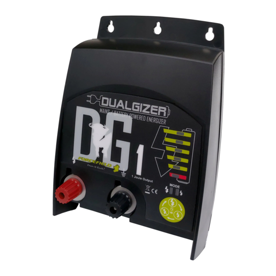
- Page 1 AC/DC Dual Power Electric Fence Energiser Installation & Operation Instructions MOUNTING HOLES OUTPUT DISPLAY MODE DISPLAY NAVI-BUTTON Adapter or Battery Input SAVE THESE INSTRUCTIONS...
- Page 2 Blank page...
- Page 3 READ BEFORE YOU INSTALL YOUR ELECTRIC FENCE ENERGISER Page 1 WARNINGS READ ALL INSTRUCTIONS BEFORE INSTALLATION AND USE. ● Only use this electric fence energiser for the purpose indicated in this manual. ● RISK OF ELECTRIC SHOCK! To reduce the risk of electric shock do not open the energiser.
- Page 4 READ BEFORE YOU INSTALL YOUR ELECTRIC FENCE ENERGISER Page 2 ● Any part of an electric animal fence that is installed along a public road or pathway shall be identified at frequent intervals by warning signs securely fastened to the fence posts or firmly clamped to the fence wires. ~ The size of the warning sign shall be at least 100 mm ×...
- Page 5 READ BEFORE YOU INSTALL YOUR ELECTRIC FENCE ENERGISER Page 3 ● DO NOT connect simultaneously to a fence and any other device such as a cattle trainer or poultry trainer. Otherwise, lightening striking your fence will be conducted to all other devices. ●...
- Page 6 READ BEFORE YOU INSTALL YOUR ELECTRIC FENCE ENERGISER Page 4 ● Electric animal fences intended for deterring birds, household pet containment or training animals such as cows need only be supplied from low output energisers to obtain satisfactory and safe performance. ●...
- Page 7 KEYS TO SUCCESSFUL ENERGISER INSTALLATION Page 5 Take care of the 5 following recommendations: 1. Grounding - Carefully install a complete ground system. Most electric fence failures are caused by an improper ground system (see Diagram 1). 2. Connections – Carefully connect lead out wire, ground wire and fence line splices.
- Page 8 ENERGISER INSTALLATION (Steps 1-6) Page 6 Step 1: Mount The Energiser Using the energiser's 3 upper mounting keyholes and the 2 lower mounting holes, drive either screws or nails into a wall or stable wooden surface to securely mount the energiser. Not all energiser mounting holes are needed, but use as many as possible to ensure the energiser is stable and will not move if the fence or power wires are pulled.
- Page 9 ENERGISER INSTALLATION continued. Page 7 Step 2 continued: The “ground system” consists of 1 or more highly conductive ground rods driven into the soil and then connected by wire to the ground terminal of your fence energiser. The ground system allows current to flow through the soil to complete the circuit needed for delivering an effective shock.
- Page 10 ENERGISER INSTALLATION continued. Page 8 Step 3: Connect the fence live (hot) terminal Note: Ensure the energiser is OFF before making this connection or you may receive a shock. 1. Unscrew the red fence terminal knob ( ) and remove it together with the top washer.
- Page 11 ENERGISER INSTALLATION continued. Page 9 Step 4 continued Properly connect the hook-up wire from the energiser to the fence line(s) using appropriate connection methods to ensure a good connection. Joints along the fence line also need to be well made to ensure a good electrical connection.
- Page 12 ENERGISER INSTALLATION continued. Page 10 Step 6: Restrain the DC Plug and Cable To avoid unwanted power disconnection or damage to the DC plug and socket, it is recommended to use the incorporated Plug Lock. This is the part attached below the DC socket. With the Plug Lock to the right, insert the DC plug into the socket.
- Page 13 ENERGISER TEST (Steps 7-8) Page 11 Step 7: Test Energiser ● With the energiser off, press and release the “Navi-Button” once. The unit will start in Full-Power Mode, putting a high voltage pulse onto the fence. The unit is in Full-Power Mode so the larger lightening bolt ( ) mode LED is lit.
- Page 14 ENERGISER TEST continued. Page 12 Step 7: Test Fence Condition Now that the energiser is turned on, you want to look for one of two conditions on the front panel LEDs (lights) to know the condition of your fence. Either green LEDs or the single red LED will flash with each fence pulse.
- Page 15 ENERGISER TEST continued. Page 13 Step 8: Test Battery Condition (continued) Battery Life Fence Indicator Battery Indicator Approx Output Approx Battery This energiser gives you many options for Voltage Charge what rechargeable battery amp hour (Ah) capacity to use. Refer to the below chart, as an example, when selecting a lead-acid 8000 green...
- Page 16 Product Specifications: Product type: Battery-Operated Electric Fence Energiser for Connection to Mains Input: External 12V DC battery or 12V Separate Power Supply Output: Up to 10kV pulsed, 1.0J, 3.0J, 5.0J Output over 3 variants IP Rating: IP44 Insulation Class: Class 2 Enclosure: ABS - UV stabilised Separate Power Supply: 100-240VAC Input.
Need help?
Do you have a question about the DUALGIZER DG1 and is the answer not in the manual?
Questions and answers