Sign In
Upload
Download
Table of Contents
Contents
Add to my manuals
Delete from my manuals
Share
URL of this page:
HTML Link:
Bookmark this page
Add
Manual will be automatically added to "My Manuals"
Print this page
×
Bookmark added
×
Added to my manuals
Manuals
Brands
MyLight Manuals
Measuring Instruments
Smart Master G3
Installation manual
MyLight Smart Master G3 Installation Manual
Smart meter for energy monitoring and management solutions
Hide thumbs
1
2
Table Of Contents
3
4
5
6
7
8
9
10
11
12
13
14
15
16
17
18
19
20
21
22
23
24
page
of
24
Go
/
24
Contents
Table of Contents
Bookmarks
Table of Contents
Table of Contents
Safety of Goods and Persons
Correct Use
Country Certification and Authorisation
Qualified Technicians
Product Markings
Contents of the Box
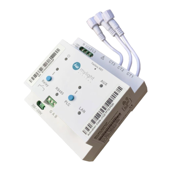
Description of the Smart Master G3
Installation Conditions
Internet Connectivity Options
Ethernet Cable Connection
PLC Plug Connection
Ethernet Cable on the Internet Router
Wi-Fi Connection on the Internet Router
Connection over an Existing PLC Circuit
Connection through a Cellular Modem
Ethernet Connection to the Cellular Modem
PLC Connection on the Cellular Modem
Electrical Connections
Power Supply Connection
Single-Phase Power Supply
Three-Phase Power Supply
Relay Connection
Extension and Current Transformer Connections
Extension Connections
Current Transformer Connections
Connection of the RS485 Accessory
Ethernet Connection
Example of Final Connections
Commissioning
Prerequisites
Switching on the Smart Master G3
Connection of the Power Line Communication (PLC)
Addition of a Mylight Systems PLC Device
Connection of an External PLC Device
Registration of the System
Maintenance and Cleaning
Commissioning
Disassembly
Recycling
Faq
Glossary
Advertisement
Quick Links
Download this manual
Installation manual
Smart Master G3 (MG3)
ENGLISH
MAI-0005- MG3 Installation manual-V1
Table of
Contents
Previous
Page
Next
Page
1
2
3
4
5
Advertisement
Table of Contents
Need help?
Do you have a question about the Smart Master G3 and is the answer not in the manual?
Ask a question
Questions and answers
Related Manuals for MyLight Smart Master G3
Measuring Instruments MyLight MC3D01RM User Manual
Three phase four wire energy meter (10 pages)
This manual is also suitable for:
Mg3
Table of Contents
Print
Rename the bookmark
Delete bookmark?
Delete from my manuals?
Login
Sign In
OR
Sign in with Facebook
Sign in with Google
Upload manual
Upload from disk
Upload from URL


Need help?
Do you have a question about the Smart Master G3 and is the answer not in the manual?
Questions and answers