Table of Contents
Advertisement
Quick Links
1
STAGE
INDICATORS
1
2
STAGE COUNT
3
4
5
6
7
8
STAGE GATE
MODE
?
?
? ? ?
TEMPO
PORTAMENTO
STAGES
GATE TIME
/ CH2 CV SET
RUN / STOP
/ MENU
2
3
4
5
1
2
3
4
5
6
7
8
?
?
? ? ?
?
?
4
5
6
3
2
7
1
8
RESET
PREV
NEXT
6
7
8
STAGE CV
1
2
3
4
5
6
7
8
CH1 CV OUT
? ? ?
?
?
? ? ?
CH1 GATE OUT
CH2 CV/GATE OUT
/ SYNC OUT
MIDI OUT
MIDI IN / RESET IN
CLOCK IN/OUT
MODE
SPLIT MODE
VOLTAGE MODE
/ GLIDE PROG
Advertisement
Table of Contents

Related Manuals for RYK Modular M185

Summary of Contents for RYK Modular M185
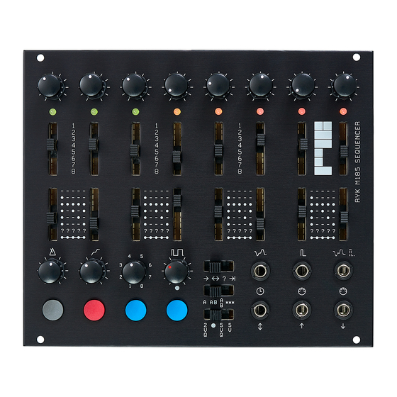
- Page 1 STAGE CV STAGE INDICATORS STAGE COUNT STAGE GATE MODE CH1 CV OUT ? ? ? ? ? ? ? ? ? ? ? ? CH1 GATE OUT TEMPO CH2 CV/GATE OUT PORTAMENTO / SYNC OUT STAGES MIDI OUT GATE TIME / CH2 CV SET MIDI IN / RESET IN CLOCK IN/OUT...
- Page 2 CV Output. [ This can be set on or off per stage, in GLIDE PROG, see VOLTAGE MODE page5 ]. stage, then low for The M185 requires a +/- 12V power supply via remaining clock pulses of the supplied standard 2x5 pin-socket ribbon STAGES the stage.
-
Page 3: Settings Menu
RUN / STOP Forward: Plays forwards SPLIT MODE Press this button to start in ascending order. Slide this switch to select or stop the internal Sequence will reset after and set the Split Mode sequence clock . the last stage set by the Stages-Control. settings [NB If using an external clock, it is a good idea to stop the internal clock first ! ]... -
Page 4: Clock In / Out
SERIAL SPLIT MODE TIP: To set up an AAAB When the sequencer is stopped, the GATE TIP: If using only the CV of CH2, a standard TIME control is used to adjust the Stored CV type structure, where Sequence A plays mono jack cable can be used instead. -
Page 5: Settings Menus
2.1 SETTINGS MENUS 1. Scale Quantise Sub Menu 5. Clock multiply ON/OFF [see page 5 for sub menu] When set ON the sequencer clock [ internal or RESET To access the settings menus, push external ] is doubled, enabling 16th notes from 2. - Page 6 2.3 LEVEL 2 SUB MENUS 2. Programmable Gate Pattern Sub Menu Once the required settings have been chosen, RUN /STOP to exit the menu back to Allows setting of custom gate patterns for push GATE MODE “?????” The level 2 SUB MENUS are indicated by Red Level 1 menu, push again to return to toggle ON/OFF LEDS, and a Green cursor LED.
-
Page 7: Utility Menu
PREV / NEXT to move the Red LED to Push Push the LEDs stop moving, before releasing the the required stage to select the subdivide With this mode the M185 can be used as a button. amount. MIDI to CV converter. The UTILITY MENU is indicated by Green Each stage represents a multiple of 6, Toggle ON/OFF LEDs, and a Red cursor LED.
Need help?
Do you have a question about the M185 and is the answer not in the manual?
Questions and answers