Advertisement
Quick Links
Advertisement

Related Manuals for SMARC SC106


Summary of Contents for SMARC SC106
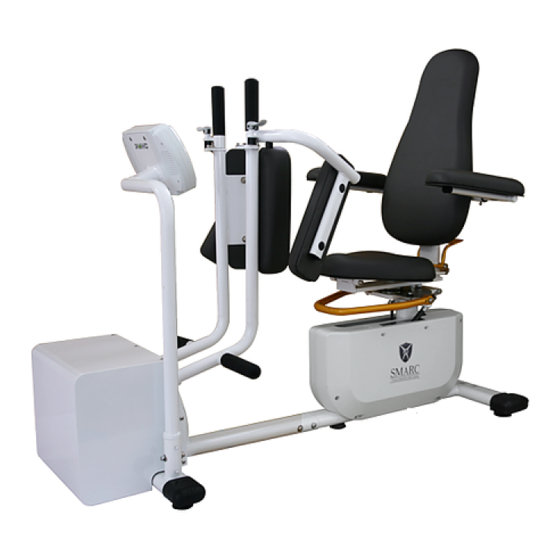
- Page 1 SC106 Core Hip Service Manual...
-
Page 2: Table Of Contents
Content Serial Number Location Safety Instruction Preventive Maintenance Specification and Assembly Guide Console and Program Description Engineer Mode Troubleshooting Parts Replacement... -
Page 3: Ch1 Serial Number Location
CH1 Serial Number Location... -
Page 4: Ch2 Safety Instruction
6. WARNING: To avoid the risk of electric shock, the equipment must only be connected to supply mains with protective earth. 7. SMARC products forms a ME SYSTEM when connected to a power supply, and can be operated at a voltage of 115V or 230 V. - Page 5 3. Avoid over-stretching to prevent strain of soft tissues and joint instability. FOR PATIENTS WITH MEDICAL NEEDS Patients may operate SMARC products under supervision of physicians or physical therapists. Users with following medical and therapeutic needs (especially over 40 years old) should consult physician or physical therapist before operating.
-
Page 6: Ch3 Preventive Maintenance
CH3 Preventive Maintenance 1. General Maintenance 1) SMARC products require only the most basic general maintenance, performed on an as- needed basis every 6~8 months. 2) Minimum qualifications of SERVICE PERSONNEL: Only technicians trained by PMHC and associated distributors are supposed to do maintenance. Please contact PMHC factory or local authorized dealer for maintenance. - Page 7 Chain Maintenance and Tightness Adjustment Applying grease Chain maintenance must be held at least once ever 6 months, depending on the frequency of use. Please apply grease to chain links and sprocket area as indicated on the left.
- Page 8 Chain Maintenance and Tightness Adjustment Tightness (tension) adjustment Step1:Loosen the nuts above and beneath the “Turn Buckle” Turn Buckle Step2:Adjust the tightness (tension) of chain via turning the “Turn Buckle”...
- Page 9 Chain Maintenance and Tightness Adjustment Step3:Check the tightness (tension) by pressing the chain. The standard tightness (tension) is 5~10 mm flexibility when pressed. Step4:Tighten the nuts...
-
Page 10: Ch4 Specification And Assembly Guide
CH4 Specification and Assembly Guide... -
Page 12: Ch5 Console And Program Description
CH5 Console and Program Description... -
Page 25: Ch6 Engineer Mode
CH6 Engineer Mode Model Setting Mode Setting... -
Page 30: Ch7 Troubleshooting
CH7 Troubleshooting Lower Control Board Wires Installation Lower Control Encoder Wire Board Power Wire Generator Power Cord Console Wire... - Page 31 1) No console display when powered on 1.1 Check the “Voltage Switch” if it has been switched to the appropriate voltage, to 115V or 230V 1.2 Check the fuse if it is functioning...
- Page 32 1.3 Change a new console to eliminate console breakdown 1.4 Check if the Transformer wires and cables are loosened or damaged Check if there is power output 1.5 Check the “Lower Control Board Power Wire is still in place Make sure the wires are properly connected (the power wire is inside the main frame tube)
- Page 33 1.6 Check if the Console Wire has been properly connected to the “Lower Control Board” 1.7 Check if the Console Wire has been properly connected to the Console...
- Page 34 2) Console angle display error Angle display breakdown or abnormal angle displayed during exercise 2.1 Check if Console Wire has been properly connected to “Lower Control Board” 2.2 Check if Encoder Wire has been properly connected to the “Lower Control Board”...
- Page 35 2.3 Check if Encoder Wire has been properly connected to the Encoder 2.4 Change Encoder or Encoder Set and see if the problem has been solved upon changing...
- Page 36 3) Resistance output error 3.1 Check if the Generator Power Cord has been properly connected 3.2 Check if power output is normal Check if there is power output Adjust Resistance (Load)
- Page 37 3.3 Change another piece of “Lower Control Board” to see if the problem has been solved upon changing 3.4 Change another piece of Generator to see if the problem has been solved upon changing.
-
Page 38: Ch8 Parts Replacement
CH8 Parts Replacement I. Tools list • Hex wrench x1 Set • Diagonal pliers x1 pcs • Needle-nose pliers x1 pcs • Phillips screwdriver x1 pcs • 10 mm Open ring wrench x2 pcs • 13 mm Open ring wrench x2 pcs •... - Page 39 II. Cover Removal Anterior Case removal Step 1: Remove the Fixation Screws (left, right and bottom) Step 2: Remove Anterior Case Fixation Screws to remove Anterior Case.
- Page 40 Seat Side Cover (left) removal Step 1: Position the seat to the very back of the frame. Step 2: Remove the Fixation Screws of Gas Spring.
- Page 41 Step 3: Remove Fixation Screws on Seat Side Cover. Step 4: Remove Seat Side Cover.
- Page 42 III. Chain Replacement Loosen the Generator Screws (no need remove). Remove Chain Lock and remove chain.
- Page 43 Ensure the Chain Gear is in parallel with Frame Gear (can be observed looking sideway), then install the chain. 4. Adjust the chain tightness by adjusting the Socket Set Screw, then lock the screw with a nut...
- Page 44 IV. Generator and Generator Chain Replacement Generator removal Step 1: Loosen the Socket Set Screw. Step 2: Remove Chain Lock and remove chain.
- Page 45 Step 3: Remove Generator Fixation Screws. Step 4: Remove the Generator towards the direction of the arrow (as indicated below).
- Page 46 Generator and generator chain installation Step 1: Position the Generator on the frame, apply Fixation Screw to attach the Generator. Step 2: Ensure the Chain Gear is in parallel with Frame Gear (can be observed looking sideway).
- Page 47 Step 3: Install the chain and fix the Chain Lock. Step 4: Adjust the chain tightness by adjusting the Upper Socket Set Screw, then lock the screw with a nut.
- Page 48 Step 6: Fix the Generator with Hex Head Cap Screws, apply torque force of 150 Kgf/cm to the screws.
- Page 49 Apply Grease to Chain: Step 1: After replacing the chains, apply grease to the chain and sprocket keys.
- Page 50 V. Gas Spring Replacement Gas Spring removal Step 1: Position the seat to the very back of the frame. Step 2: Remove the Fixation Screw of the Gas Spring.
- Page 51 Step 3: Remove Phillips Screws. Step 4: Remove the Seat Side Cover (Left).
- Page 52 Step5: Loosen the Fixation Screw Cap of gas spring.
- Page 53 VI. Wires and Parts Diagram Wires and Parts connection diagram...
- Page 54 Parts position Parts Name Quantity WEE-0000102-9 Electro-Magnetic System – Long Axis Version WCM-0000475-7 Encoder Control Set (A) WEE-0000139-6 Console Set WEE-0000147-8 Power Supply Unit - short WEE-0000172-1 Transformer WEE-0000084-6 Electro-Magnetic System Cable-L400 WEE-0000157-4 Encoder Cable-L500 WEE-0000111-8 Console Cable-L1800 WEE-0000159-8 Power Cord-L900 WEE-0000164-9 LCB Extension Cable-L700 WEE-0000055-5...
Need help?
Do you have a question about the SC106 and is the answer not in the manual?
Questions and answers