
Related Manuals for Tecmec Sirio HH Series

Summary of Contents for Tecmec Sirio HH Series
- Page 1 Sirio HH Use and maintenance manual Page 1 of 28 Instruction n° - Rev. of 06/07/2016 Sirio HH Use and maintenance manual Copyright © 2016 Tecmec S.r.l. Translated from the original instructions...
-
Page 2: Table Of Contents
ECHNICAL FEATURES STANDARD ECHNICAL FEATURES OF THE MODEL ATEX ECHNICAL FEATURES OF THE MODEL IRING DIAGRAMS 10.1 IRING ELECTRICAL PANEL STANDARD MOTOR SINGLE PHASE 10.2 ATEX IRING SINGLE PHASE MOTOR ISPOSAL Copyright © 2016 Tecmec S.r.l. Translated from the original instructions... - Page 3 Sirio HH Use and maintenance manual Page 3 of 28 Instruction n° - Rev. of 06/07/2016 PARE PARTS 12.1 TANDARD ASEMENT 12.2 ASEMENT 12.3 ODULE 12.4 RANSMISSION SHAFT Copyright © 2016 Tecmec S.r.l. Translated from the original instructions...
-
Page 4: Eneral Information
The identification label, is located on the left side of the structure, with the below mentioned data: Safety and Health Requirements Symbols Manufacturer Data CE Mark Production Year Serial Number Univocal Machine Code Motor Protection Class Electrical Characteristics Copyright © 2016 Tecmec S.r.l. Translated from the original instructions... -
Page 5: Ce Declaration
Sirio HH Use and maintenance manual Page 5 of 28 Instruction n° - Rev. of 06/07/2016 1.3 CE Declaration Copyright © 2016 Tecmec S.r.l. Translated from the original instructions... -
Page 6: Reference Standards
In particular, the warranty will not cover any damage due to the transport, or non compliance with the installation and operating instructions, or usage by unauthorized personnel, or for reasons not caused by the manufacturer. Copyright © 2016 Tecmec S.r.l. Translated from the original instructions... -
Page 7: Equipment Description
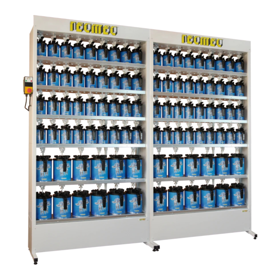
The unique feature of this equipment is to maintain homogeneous, over time, the colorants contained in the cans (provided with suitable lids provided separately from Tecmec). In order to avoid accidents or injury to person, or and things, the equippment have to be used by trained personnel. -
Page 8: Safety
It's important to make the necessary assessment of the site, and follow the requiring and characteristic rules of the electrical system, to ensure that they are not a cause of accidents or injuries. Copyright © 2016 Tecmec S.r.l. Translated from the original instructions... -
Page 9: Working Zones
The dispenser is designed to handle colorant / pastes of various types. Prior to their use, follow the instructions warning and safety instruction on each individual can / package, and on the data sheet issued by the producer. Copyright © 2016 Tecmec S.r.l. Translated from the original instructions... -
Page 10: Symbols Shown On The Eqiupmet
3.7 Intended use of the equipment The unique feature of this equipment is to maintain homogeneous, over time, the colorants contained in the cans (provided with suitable lids provided separately from Tecmec). 3.8 Non intended use Any other use of this equipment that are not described in this manual are considered improper and therefore prohibited. -
Page 11: Transport And Handling
For obvious safety reason it is forbidden to move the assembled equipment. For movement over long distance, the equipment MUST be packed and secured on pallets, as when it was delivered. Copyright © 2016 Tecmec S.r.l. Translated from the original instructions... -
Page 12: Installation
Secure the extension support using the M8 screws and nuts. Screw without over tighten the 4 feet and nuts. Secure the control panel to the control panel using the M4 screws. Copyright © 2016 Tecmec S.r.l. Translated from the original instructions... - Page 13 Tighten the grain / screw of the joint with the supplied key. Slide the protections between them, until they go in contact with the structure. Copyright © 2016 Tecmec S.r.l. Translated from the original instructions...
- Page 14 Repeat the operation H for all the agitated modules. Connect on the rear part of the dispenser the various structure modules, with the ground plate. Copyright © 2016 Tecmec S.r.l. Translated from the original instructions...
- Page 15 It is mandatory to execute this operation. Not performing the above operation carries risks for the end user. Secure the frontpanel (optional) at the top of the last module. Copyright © 2016 Tecmec S.r.l. Translated from the original instructions...
- Page 16 Remove the front panel of the basement Secure the two structure using toothed washer and M6 srews. Connect the reducers through the shaft and transmission joints. Overlap and secure the successive G-H-I-L. modules as step Copyright © 2016 Tecmec S.r.l. Translated from the original instructions...
- Page 17 Page 17 of 28 Instruction n° - Rev. of 06/07/2016 Connect the two columns with the M6 screws and nuts, using the holes in the module posts. Complete the installation by performing points Copyright © 2016 Tecmec S.r.l. Translated from the original instructions...
-
Page 18: Use
Cycle mode active ( agitation motor off ready to start ) Note: To restart the motor during the pause period, press the red STOP button, wait a few seconds and press the green START button. Copyright © 2016 Tecmec S.r.l. Translated from the original instructions... -
Page 19: Costumized Agitation And Pause Settings
When placing the can make sure that the lid is properly positioned. The reference point are 2: the spout against the anti rotation "nail", and the fork against the reference points. Copyright © 2016 Tecmec S.r.l. Translated from the original instructions... -
Page 20: Aintenance
2- Once the procedure is done, restore the equipment by pressing the START button. For any other kind of issues, or doubts, please contact the Customer Service Dep. in Tecmec. 7.2 Non use periods... -
Page 21: Roubleshooting
The panel is on, but the motor Fuse blown. Change fuse. is not working. For any other kind of issues, or doubts, please contact the Customer Service Dep. in Tecmec. Copyright © 2016 Tecmec S.r.l. Translated from the original instructions... -
Page 22: Echnical Features
MEC 80–0,75kW 4 poli 220/240V–50Hz Construction: Thermal protection: Thermal probe inside the winding NC-250V-25A Capacitor: 40µF inside the terminal box Reference standards: IEC 34-1 - 73/23 CEE – 89/336 CEE Copyright © 2016 Tecmec S.r.l. Translated from the original instructions... -
Page 23: Technical Features Of The Atex Model
Thermal probe inside the winding PTC 120°C Capacitor: 2x12,5 µF inside the terminal box Reference standards: EN 60079-0 2004; EN60079-1 2004; EN60079-4 2003; EN61241-0 2006;EN61241-12004;EN60529 Ottobre 1991; EN 60034-5 Ottobre 1991 Copyright © 2016 Tecmec S.r.l. Translated from the original instructions... -
Page 24: Wiring Diagrams
Sirio HH Use and maintenance manual Page 24 of 28 Instruction n° - Rev. of 06/07/2016 IRING DIAGRAMS 10.1 Wiring electrical panel standard motor single phase Copyright © 2016 Tecmec S.r.l. Translated from the original instructions... -
Page 25: Wiring Atex Single Phase Motor
Sirio HH Use and maintenance manual Page 25 of 28 Instruction n° - Rev. of 06/07/2016 10.2 Wiring ATEX single phase motor Copyright © 2016 Tecmec S.r.l. Translated from the original instructions... -
Page 26: Disposal
For the disposal of colorants, or parts of machine contaminated by them, see to the safety data sheets of the respective products. Copyright © 2016 Tecmec S.r.l. Translated from the original instructions... - Page 27 103831 EMERGENCY BUTTON 103833 MOTOR ADPE V220 ATEX 103584 REDUCER U40FP 7,5/1 ATEX 103613 REDUCER U40FP 10/1 ATEX 102527 TOOTHED BELT A18 102001 TOOTHED BELT A19 017312 JOINT Ø14/ESAG. 12 Copyright © 2016 Tecmec S.r.l. Translated from the original instructions...
- Page 28 Shaft Al L=658,5 019583 Shaft Al L=248,5 019584 Shaft Al L=508,5 019585 Shaft Al L=767 019586 Shaft Al L=841.5 019587 Shaft Al L=993.5 019588 Shaft Al L=1025 019589 Shaft Al L=258 Copyright © 2016 Tecmec S.r.l. Translated from the original instructions...
Need help?
Do you have a question about the Sirio HH Series and is the answer not in the manual?
Questions and answers