
Related Manuals for ENC EDS300 Series


Summary of Contents for ENC EDS300 Series
- Page 1 ISO9001:2015 Quality Management System Authentication EDS300 Series Ver.1.1 0.2-3.7KW Users’ Manual SHENZHEN ENCOM ELECTRIC TECHNOLOGIES CO., LTD...
- Page 2 Assembling wiring, parameter setting, troubleshooting and daily maintenance notice are available in this manual. To make sure that you can correctly assemble and operate EDS300 series inverters to exert their excellent performance, please read this user manual detailedly before you assemble the device and conserve the manual appropriately before the end-user get them.
-
Page 3: Table Of Contents
Contets Contents 1 Safety information and use notice points .............. 1 1.1 Safety Precautions .................... 1 1.2 Use Range ......................2 1.3 Use Notice Points ..................... 2 1.4 Scrap Notice Points ..................3 2 Type and specification of the inverter ..............4 2.1 Incoming Inverter Inspect ................ - Page 4 Contets 6 Maintenance ......................35 6.1 Routine maintenance ..................35 6.2 Inspection and replacement of damageable parts .......... 35 6.3 Repair guarantee ..................... 36 6.4 Storage ......................36 7 Modbus Communication Protocol ............... 37 7.1 Summarization ....................37 7.2 Networking mode for communication networking ........37 7.3 Communication mode ..................
-
Page 5: Safety Information And Use Notice Points
Safety information and use notice points 1 Safety information and use notice points In order to ensure the safety of your personal and equipment, before using the inverter please read this chapter of contents conscientiously. 1.1 Safety Precautions There are three kinds of safe relevant warnings in this service manual, they are as follows: Symbol Symbol description... -
Page 6: Use Range
1.3 Use Notice Points (1) EDS300 series inverter is voltage-type inverter, so temperature, noise and vibration slightly increasing compared to power source running when using, belongs to normal phenomenon. -
Page 7: Scrap Notice Points
Safety information and use notice points inverter output and the motor, please guarantee the inverter is switched on/off without output, otherwise may damage the inverter. (8) The inverter may meet with mechanical resonance of the load within certain range of frequency output, can set up jumping frequency to evade. (9) Before using, should confirm the voltage of the power is within the working voltage range allowed, otherwise should vary voltage or order special inverter. -
Page 8: Type And Specification Of The Inverter
Type and specification of the inverter 2 Type and specification of the inverter 2.1 Incoming Inverter Inspect (1) Check if there is damage during transportation and inverter itself has damage or fall-off parts. (2) Check if parts presented in packing list are all ready. (3) Please confirm rated data of the inverter is in line with your order requirement. -
Page 9: Series Type Explanation
Type and specification of the inverter 2.4 Series type explanation Table 2-1 series type explanation Rated power Rated output Adapted motor Inverter type (KVA) current(A) (KW) EDS300-2S0002 EDS300-2S0004 EDS300-2S0007 0.75 EDS300-2S0015 EDS300-2S0022 EDS300-4T0007 0.75 EDS300-4T0015 EDS300-4T0022 EDS300-4T0037 2.5 Appearance and parts name explanation top cover analog potentiometer keypad... -
Page 10: Outer Size And Gross Weight
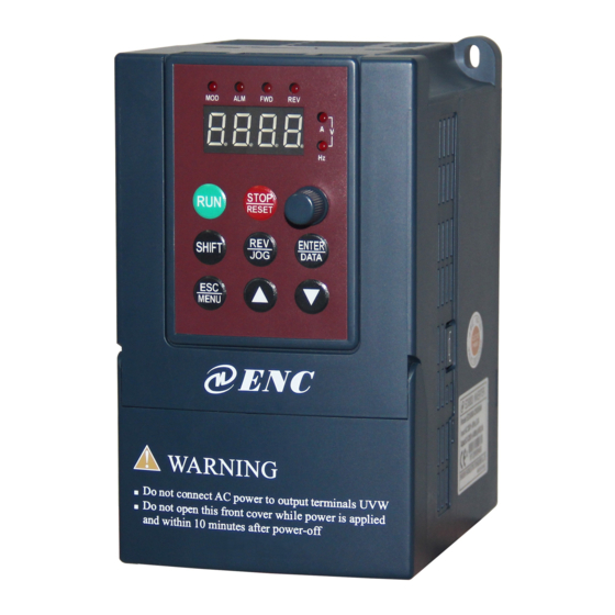
Type and specification of the inverter 2.6 Outer size and gross weight WARNING Do not connect AC power to output terminals UVW Do not open this front cover while power is applied and within 10 minutes after power-off Fig.a Fig.b Fig.2-4 Outline Image Table 2-2 EDS300-2S0002N~EDS300-4T0015N Mounting size Fixing... -
Page 11: Product Technic Index And Spec
Type and specification of the inverter 2.8 Product Technic Index And Spec. Item Item description 3 phase 380V, 50Hz/60Hz; Rating volt. frequency Single phase 220V, 50Hz/60Hz Input 3 phase voltage: 320V~460V; Allowed work volt. range Single phase voltage: 200V~260V Voltage 400V grade: 0~380V;... - Page 12 Type and specification of the inverter Can display setting frequency, output frequency, output voltage, output LED display current etc. in total 14 kinds of parameter Keypad Lock the button Lock all or part of the buttons(analog potentiometer can’t be locked) Over-current protection, over-voltage protection, lack-voltage protection, Protection function over-heat protection, over-load protection, missing phase protection (in...
-
Page 13: Installation And Wiring
Installation and wiring 3 Installation and wiring 3.1 Installation ambient 3.1.1 Demand for installation ambient (1) Installed in drafty indoor place, ambient temperature within -10ºC~40ºC, need external compulsory heat sink or reduce the volume if temperature exceeds 40ºC. (2) Avoid installing in place with direct sunlight, much dust, floating fibre and metal powder. -
Page 14: Parts Disassembly And Installation
Installation and wiring 3.2 Parts disassembly and installation 3.2.1 Key board disassembly and installation (1) Disassembly Let the forefinger press finger inlet on the keypad, Depress fixing flexible plate on the top lightly, Draw it outward, then you can disassemble the keypad. (2) Assembly First place the fixing hook at the bottom of keypad onto mounting claw on keypad mounting hole, let forefinger press fixing flexible plate on top of keypad and... -
Page 15: Main Loop Terminal Wiring
Installation and wiring Inverter Fig.3-3 Banned magnetic control conductor and absorbing capacitance between inverter and motor 3.4 Main loop terminal wiring 3 Phase Breaker EDS300 Power Supply Fig.3-4 Main loop simple wiring 3.4.1 Connection between inverter and fitting parts (1) Must assemble disjunction device such as isolation switch etc. between power source and the inverter to assure personal safety when repairing the inverter and needing compulsory power off. -
Page 16: Main Loop Terminal Wiring
Installation and wiring (6) Output side EMI filter Can use EMI filter to inhibit emission disturbance noise and wire leakage current from output side. Isolation switch (7) AC output reactor Breaker or fuse Advise assembling AC output reactor to avoid motor insulation damage, too large AC input reactor (in option) over current and inverter frequent protection when connecting wire from inverter to... -
Page 17: Basic Running Wiring Diagram
Installation and wiring L1 、 L2 、 L3 3 phase AC input end DC volt. Positive terminal External connect to brake EDS300-4T0022 resistor reverse terminal EDS300-4T0037 L1 L2 L3 P+ PB U 、 V 、 W 3 phase AC output end Grounding terminal 3.5 Basic running wiring diagram Braking unit(External,fitting part,interface at the right side of inverter) -
Page 18: Control Loop Collocation And Wiring
Installation and wiring 3.6 Control loop collocation and wiring 3.6.1 Location & function of terminal and jump-wire: For location of terminal and switch on the CPU board, please see Fig.3-7. Function description of terminal provided for the user, please see Table 3-2 , function and setup description of switch, please see Table 3-3. - Page 19 Installation and wiring (2) CN2 terminal function description as Table 3-4. Table 3-4 CPU board CN2 terminal function table Item Symbol Name Function description Spec Forward run Forward reverse run command, command see F5.08 group double-wire and command three-wire control function Reverse run description command...
-
Page 20: Analog Input Output Terminal Wiring
Installation and wiring 3.6.3 Analog input output terminal wiring (1) CCI terminals accept analog voltage signal input, input voltage(0-10V), input current(0-20mA). Wiring as follow: +10V 0~+10V EDS300 ― Shielded wire close end grounded Fig.3-8 CCI terminal wiring diagram (1) When input analog signal , can connect filter capacitor or common module inductance between CCI and GND. - Page 21 Installation and wiring 232/485 Converter Shielded Signa Pin No. Terminal Name cable Shell Power supply Sending Receiving 5V Grounding Terminal Name Name Terminal Negative end Negative Positive end Positive Fig. 3-10 RS485 communication wiring (4) Multiple inverters can be connected together per RS485 and 31pcs inverter can be connected together at most.
-
Page 22: Function Parameter Schedule Graph
Function parameter schedule graph 4 Function parameter schedule graph 4.1 Symbol description Parameter can’t be changed in process of running × ---- Parameter can be changed in process of running ○ ---- Read-only parameter, unmodifiable * ---- 4.2 Function parameter schedule graph F0-Basic run function parameter group Function Factory... - Page 23 Function parameter schedule graph F0.07 Accelerating 0: Second × decelerating time unit 1: Minute F0.08 Acce time 1 0.1 ~ 6000.0 20.0 ○ F0.09 Dece time 1 0.1 ~ 6000.0 20.0 ○ F0.10 Upper limit freq. Lower limit freq. ~ 400.00Hz 0.01Hz 50.00Hz ×...
- Page 24 Function parameter schedule graph F2-Auxiliary run function parameter group Function Modifi Factory Name Set range Unit default code -cation F2.00 Analog filter time 0.00 ~ 30.00s 0.01s 0.20s ○ constant F2.01 Forward reverse run 0.0 ~ 3600.0s 0.1s 0.1s ○ dead-section time F2.02 Automatic energy...
- Page 25 Function parameter schedule graph F2.12 LED display 0000 ~ 1111 0110 ○ control 2 LED Units digit: Reserved LED Tens digit: Analog input CCI 0: Not display 1: Display LED Hundreds digit: Reserved LED Thousands digit: Reserved F2.13 Parameter operation LED Units digit: ×...
- Page 26 Function parameter schedule graph F2.22 Acce time 4 0.1 ~ 6000.0 20.0 ○ F2.23 Dece time 4 0.1 ~ 6000.0 20.0 ○ F2.24 Acce time 5 0.1 ~ 6000.0 20.0 ○ F2.25 Dece time 5 0.1 ~ 6000.0 20.0 ○ F2.26 Acce time 6 0.1 ~...
- Page 27 Function parameter schedule graph 2: CCI analog provision 3: Keypad potentiometer provision Feedback 0: Reserved ○ F3.02 channel selection 1: CCI analog input Specified value 0.000 ~ 9.999V (SetF3.00=1 , F3.21=9.999) 0.001 0.200 ○ digital setting F3.03 Target pressure 0.000 ~ F3.21Mpa (set F3.00=2) 0.001 0.200 ○...
- Page 28 Function parameter schedule graph supervision parameter 1: Output frequency selection 2: Output current 3: Output voltage 4: DC bus bar voltage 5: Motor speed 6: Heat sink temperature 7: Run time 8: Accumulative run time 9: Input terminal status 10: Output terminal status 11: Analog input VCI/PID provision 12: Analog input CCI/PID feedback 13: Reserved...
- Page 29 Function parameter schedule graph LED Tens digit: 0: Start again from first section 1: Continue to run at mid-section frequency 2:Continue to run from operation frequency of interruption moment LED Hundreds digit: PLC run time unit 0: Second 1: Minute LED Thousands digit: PLC running state power off treatment method 0: Power off no memory...
- Page 30 Function parameter schedule graph function selection 1: Multi-step speed control terminal 1 2: Multi-step speed control terminal 2 3: Multi-step speed control terminal 3 4: Multi-step speed control terminal 4 5: External forward run jog control 6: External reverse run jog control 7: Accel / Decel time selecting terminal 1 8: Accel / Decel time selecting terminal 2 9: Accel / Decel time selecting terminal 3...
- Page 31 Function parameter schedule graph F5.08 FWD/REV operation 0: two-line control mode 1 × mode selection 1: two-line control mode 2 2: three-line control mode 1 3: three-line control mode 2 F5.09 UP/DOWN rate 0.01 ~ 99.99Hz/s 0.01 1.00 ○ Hz/s Hz/s F5.10 Reserved...
- Page 32 Function parameter schedule graph F6.05 Triangle wave rising 0.0 ~ 98(%) (Triangle wave rising time) 0.1(%) 50.0(%) ○ time F6.06 Traverse preset 0.00 ~ 400.00Hz 0.01Hz 0.00Hz ○ frequency F6.07 Traverse preset 0.0 ~ 6000s 0.1s 0.0s ○ frequency latency time F7-Frequency provision function parameter group Function Factory...
- Page 33 Function parameter schedule graph interval F9.03 Motor overload protection 0: No action × mode selection 1: Inverter cut off output at once F9.04 Motor overload protection 20.0 ~ 120.0 ( % ) 0.1(%) 100.0 × coefficient F9.05 Overload alarm checkout 20 ~...
- Page 34 Function parameter schedule graph FF.02 Manufacturer special parameter FF.0X C-Monitoring function parameter group Function Factory modifi Name Set range code unit default cation C-00 Set frequency Current set frequency 0.01HZ C-01 Output frequency Current operating frequency 0.01HZ C-02 Output current Set current effective value 0.1A C-03...
-
Page 35: Trouble Shooting
Trouble shooting 5 Trouble Shooting 5.1 Failure and countermeasure Possible failure types in EDS300 are shown in Table 5-1 and failure code is from E001 to E023. Some failure code is reserved for intelligent automatic diagnosis function which will be executed continuously in future. When failure takes place in the inverter, the user should check according to note of this table first and record failure phenomena detailedly. - Page 36 Trouble shooting speed process Input voltage change abnormally Assemble reactor Use energy consumption Load inertia is a bit big subassembly Control power Check input power supply or look E007 supply Unwonted input voltage for service overvoltage Accel time is set to too short Prolong accelerating time Reduce DC injection braking DC injection braking is too big...
- Page 37 Trouble shooting control board loose Unwonted current wave caused by Check wiring missing output phase etc. Assistant power supply damaged Look service from and drive voltage lacking manufacturer or agent Look service from Unwonted control board manufacturer or agent Use sudden stop STOP Look up operation mode in non-keypad run mode...
-
Page 38: Failure Record Lookup
Trouble shooting P.OFF Under voltage Under voltage check spot input voltage 5.2 Failure record lookup This series inverter can record the latest 6 times failure code and inverter run parameter of the last fault, to search these information can contribute to finding out fault cause. -
Page 39: Maintenance
6 Maintenance 6.1 Routine maintenance When you use EDS300 series you must assemble and operate it according to demand listed in this 《 service manual 》 strictly. During run state, temperature, humidity, vibration , parts aging and wearing may affect it and potential fault occur. -
Page 40: Repair Guarantee
Maintenance Abnormal noise, even oscillation sound may occur if the fan have wearing bearing, aging blade, here replacement of the fan should be considered. (2) Filter electrolyte capacitance When frequent load-changing causes pulsating current increasing and aging electrolyte under high ambient temperature, the electrolyte capacitance may be damaged and here should replace it. -
Page 41: Modbus Communication Protocol
Modbus Communication Protocol 7 Modbus Communication Protocol 7.1 Summarization We provide general RS485 communication interface in our inverters for the user. This interface can communicate with upper device (such as HMI, PC, PLC controller and etc.), To centralized monitoring to the inverter (such as to set inverter parameter, control inverter running, read working condition of the inverter). -
Page 42: Rtu Communication Mode
Modbus Communication Protocol 7.4 RTU Communication Mode 7.4.1 Data frame format Using RTU mode, messages are start to send in no less than 3.5 character time interval pause. The first field transmitted is device address, the character you can transfer is hexadecimal 0x00 ~ 0xFF. Network equipment Continuously monitor the bus, including pauses time. -
Page 43: Data Communication Address Allocation
Modbus Communication Protocol CRC check value low byte Be calculated CRC check value high byte Be calculated The contents of slave answer package : number of parameter value bytes Address 0000H content high byte Address 0000H content low byte Address 0001H content high byte Address 0001H content low byte CRC check value low byte Be calculated... - Page 44 Modbus Communication Protocol corresponding to function code parameter’s group internal code. For example: F3.21 function code’s communication address is 0315H, 03H is the hex form of group number 3, 15H is the hex form of group internal code 21. F0.00~F9.11 communication address is 0000H~090BH, fault record parameter initial address of Fd group is 0D00H.
-
Page 45: Communication Error Processing
Modbus Communication Protocol C-09 Input terminal status 1009H C-10 Output terminal status 100AH C-11 Reserved C-12 Analog input CCI value 100CH C-13 Reserved C-14 Reserved 7.6 Communication error processing Inverter receiving data packet detecting error, when it finds read-write parameter address or parameter value illegal, answer to the host with communication error answer packet. - Page 46 Modbus Communication Protocol 7.7.2 Stop 1# inverter running Host command frame Slave respond frame 7.7.3 Set 1# inverter specified value to 50Hz Host command frame Slave respond frame 7.7.4 Read 1# inverter running state Host command frame (Number of Slave respond respond value frame bytes ) 02...
-
Page 47: Crc Check Mode
Modbus Communication Protocol 7.8 CRC check mode CRC checksum value calculating function written by C language is as follows: unsigned int cal_crc_value (unsigned char *pval, unsigned char len) unsigned int crc_value=0xFFFF; unsigned int i; while(len--) crc_value ^= *pval++; for(i=0; i<8; i++) if(crc_value &... -
Page 48: Appendix A Serial Port 485 Communication Protocol
Appendix A Serial port 485 communication protocol Appendix A Serial port 485 communication protocol A.1 Summarization We provide general RS485/RS232 communication interface in our Inverters for the user. Through this communication interface upper device (such as PC, PLC controller etc.) can perform centralized monitor to the inverter (such as to set inverter parameter,control run of inverter, read work state of the inverter) and also long-distance control keypad can be connected to realize various usage requirement of the user. - Page 49 Appendix A Serial port 485 communication protocol A.2.3 Transport mode Asynchronous serial , semiduplex transport mode. Default format and transport rate: 8-N-1, 9600bps.For specific parameter setting please see description for F2.14 ~ F2.17 group function code. (Remark: Below definition is only effective under series port RS485 communication mode, and definition for other parameters are the same as original) F2.14 Communication LED first bit: baud rate selection...
- Page 50 Appendix A Serial port 485 communication protocol response Definition head address Index area Setting data area Checkout area End area Sending byte Fig. A-2 Command/response frame format Remark: (1) “Setting data area” and “run data area” may not be existent in some command/data frame format, so in protocol command list it’s marked with“nothing”.
- Page 51 Appendix A Serial port 485 communication protocol Get ready Don’t allow Don’t allow Get ready Don’t allow Don’t allow Frame error Species 2>: command code= “11” ~ “15 ” , 5 kinds of function command which mainframe send to auxiliary device, for detail please see protocol command list. Table A-2 Response code meanings for command code “11~15”...
- Page 52 Appendix A Serial port 485 communication protocol Decelerating run over voltage reserved Constant speed run over voltage reserved Controller power supply over voltage Under voltage Inverter overload System disturbance Motor overload reserved Inverter over heat reserved reserved PROM read and write error reserved (5) Checkout sum Data meanings: frame checkout,4 byte, ASCII.
- Page 53 Appendix A Serial port 485 communication protocol Read inverter state 11 00 0F -010B000F01A9/r Auxiliary device 12 00 00 -010C00000194/r run command Set current run 12 00 01 -010C00010FA00 0.01Hz Set freq.=40.00Hz frequency 27C/r provision of -010C00020FA00 0.01Hz Auxiliary device Auxiliary device 12 00 02 0Hz-hig run with run freq.
- Page 54 Appendix A Serial port 485 communication protocol Accelerating time1 14 00 09 0~8CA0 ~010E000E03E80 0.1S Set function code F0.08 28B\r F0.08 to 10.0s Decelerating time1 14 00 0A 0~8CA0 ~010E000F03E80 0.1S Set function code F0.09 28C\r F0.09 to 10.0s Query auxiliary device software 15 00 00 ~010F00000197\r...
- Page 55 Appendix A Serial port 485 communication protocol If want to read parameter of F2.11 function code, order index=020B; If want to read parameter of F2.15 function code, order index=0212; If want to read parameter of F2.13 function code, order index=0210; Function Decimal Function...
-
Page 56: Appendix B Braking Resistance
As all the energy is consumed by the braking resistance. EDS300 series’ the built-in braking unit is optional and you can add external braking resistance , But the external resistance need booking. - Page 57 Shenzhen Encom Electric Technologies CO., LTD. Address: 5F, Bldg.4, Minqi Technology Park, Lishan Rd., Nanshan Area, Shenzhen 518055, China Website: www.encvfd.com E-mail: encvfd@encvfd.com encvfd@enc.net.cn Tel: +86-755-26984485 Fax: +86-755-26985120...
Need help?
Do you have a question about the EDS300 Series and is the answer not in the manual?
Questions and answers