Table of Contents
Advertisement
Quick Links
Advertisement
Table of Contents

Related Manuals for Terumo BCT Quantum Cell Expansion System


Summary of Contents for Terumo BCT Quantum Cell Expansion System
- Page 1 Quantum ® Cell Expansion System SOFTWARE VERSION 2.1 Operator’s Manual...
- Page 2 Quantum Cell Expansion System ® Operator's Manual for Software Version 2.1 Part No. 104101-164 Reorder No. 720394-002 2016-01...
- Page 3 Terumo BCT is either a registered trademark or a trademark of Terumo Corporation. Quantum is a registered trademark of Terumo BCT, Inc. The Quantum Cell Expansion System is covered by one or more of the following patents: United States: 7718430; 8163555; 8309347; 8321145;...
-
Page 4: Table Of Contents
Contents 1: Preface About this Manual ............................. 1-2 Document Conventions ............................. 1-2 Warning, Caution, and Note Definitions ......................1-3 Intended Use ..............................1-3 Warnings for Use ............................... 1-4 System Warnings ............................1-4 Service Warnings ............................1-5 Electrical Warnings ............................ 1-5 Cell Expansion Process Warnings ...................... - Page 5 Quantum System Cell Expansion Sets ......................2-13 Accessory Sets ............................2-14 About User Authentication ..........................2-15 User Role ..............................2-15 Signing In to the System .......................... 2-16 Signing Out of the System ........................2-16 Changing Your Password ......................... 2-16 Turning On the Quantum System ........................2-18 Turning Off the Quantum System ........................
- Page 6 Entering Pump Rates ............................6-7 Automatically Calculated Pump Rates ....................... 6-7 Outlet ................................. 6-9 Selecting an Outlet ............................ 6-9 Rocker ................................6-11 In Motion ..............................6-11 Stationary ..............................6-13 Selecting Stationary as the Rocker Setting ....................6-13 Stop Condition ..............................6-14 Manual ..............................
- Page 7 Attach Cells ..............................10-7 Load Cells With Uniform Suspension ......................10-9 11: Feed and Add Tasks Feed Cells With Ultrafiltration ......................... 11-2 Feed Cells ................................. 11-4 Add Bolus ................................. 11-6 Add Bag Contents ............................11-8 Add Fluid Continuously ..........................11-10 Add Fluid Continuously With Ultrafiltration ....................
- Page 8 Maintaining the Quantum System ........................16-2 Cleaning the System ............................16-2 Disinfecting the System ............................ 16-3 Performing Preventive Maintenance ......................... 16-3 17: System Specifications System Specifications ............................17-2 Environmental Specifications ........................17-2 Electrical Power and Safety Specifications ....................17-2 Physical Specifications ..........................17-3 Touch Screen Specifications ........................
- Page 9 Quantum Cell Expansion System • Operator's Manual for Software Version 2.1 ®...
- Page 10 Preface Quantum Cell Expansion System • Operator's Manual for Software Version 2.1 ®...
-
Page 11: About This Manual
Preface About this Manual ® This manual is written for personnel who are responsible for operating the Quantum Cell Expansion System. It includes information and instructions on how to operate, troubleshoot, and maintain the system. You should read and understand the information in this manual before operating the system. Document Conventions This document uses certain conventions to help you identify information. -
Page 12: Warning, Caution, And Note Definitions
Expanded cell products for use in human subjects or patients must comply with all applicable country-specific regulatory requirements. The Quantum Cell Expansion System, a functionally closed cell expansion system, may be used to grow adherent and suspension cells in laboratory, clinical, and manufacturing environments. -
Page 13: Warnings For Use
13. It is the responsibility of the user to determine any effect residual EtO may have on cells that are cultured in the Quantum system. 14. Use only power cords specified by Terumo BCT. The use of inadequately rated cords could possibly cause property damage or bodily harm. -
Page 14: Service Warnings
Service Warnings 1. Only a qualified service representative should service or modify the device. Any modifications must be approved in writing by Terumo BCT. 2. Turn off the primary power switch and unplug the device before cleaning. 3. Use a cleaning technique that does not place your finger in a vulnerable position. For example, you can clean the area around the valve with a cotton swab or by using a flossing technique. -
Page 15: Cautions For Use
9. At least two people are needed to lift the Quantum system. Use proper lifting techniques when lifting the Quantum system. 10. Use only the cell expansion sets and the accessory sets that Terumo BCT manufactures for the Quantum system. - Page 16 Cautions for Use 3. It is very important that the operator address any leaks that arise when a cell expansion set is in use because a set may occasionally fail. If a cell expansion set fails, it could result in the loss of cell products or the introduction of air into the set.
-
Page 17: Service Information
Terumo BCT. Return of Used Product If for any reason this product must be returned to Terumo BCT, Inc., a returned goods authorization (an RGA number) is required from Terumo BCT prior to shipping. -
Page 18: Use Of Additional Devices And Supplies During Cell Expansion
Use of Additional Devices and Supplies During Cell Expansion Use of Additional Devices and Supplies During Cell Expansion You need some or all of the following devices and supplies when using the Quantum system: • A tubing pump • A tubing sealer •... - Page 19 Preface 1-10 Quantum Cell Expansion System • Operator's Manual for Software Version 2.1 ®...
- Page 20 Introduction Quantum Cell Expansion System • Operator's Manual for Software Version 2.1 ®...
-
Page 21: Quantum System Overview
Introduction Quantum System Overview The Quantum Cell Expansion System is an automated system for growing adherent and suspension cells in a functionally closed environment. The term “functionally closed” is often used in the FDA‑regulated blood and blood component industry to describe systems that are closed at the point of manufacture except for tubing with pre‑connected sterile barrier filters on spike and port connections, and/or... -
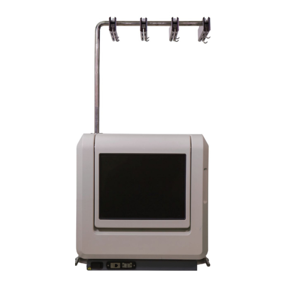
Page 22: Quantum System Components
Quantum System Components Quantum System Components This section describes the components of the Quantum system. Operators should become familiar with the location and function of the components before using the system. Device Front Figure 2-1: Device (external front view) Table 2-1: Components on the front of the device Location Component Function... - Page 23 Introduction Table 2-1: Components on the front of the device (continued) Location Component Function Auxiliary power switch Allows you to turn on and turn off the pumps, valves, heater, computer, and touch screen, but does not affect the internal power. Ethernet port Allows service personnel to connect the Quantum system to an external device for the purpose of transferring data.
- Page 24 Quantum System Components Table 2-2: Components on the back of the device Location Component Function Rear Ethernet port Allows you to connect the Quantum system to an external device or a local network for the purpose of transferring data. External gas connector Connects the external gas supply to the system.
- Page 25 Introduction Table 2-3: Components inside the incubator Location Component Function Mounting plate Contains the pumps, the valves, the rocker and rocker arm, the external mounting clips, the internal mounting clips, and all the fluid detectors. External mounting clips Hold the tubing organizer in place. The external mounting clips are located along the perimeter of the mounting plate.
-
Page 26: Pumps
Quantum System Components Pumps There are four pumps located on the mounting plate, as shown in Figure 2-4. Table 2-4 describes the function of each pump. Figure 2-4: Location of the pumps Table 2-4: Function of the pumps Location Component Function EC inlet pump Pumps fluid from an inlet bag to the EC circulation loop. - Page 27 Introduction Parts of a Pump Figure 2-5 shows the parts of a pump, and Table 2-5 describes each part. Figure 2-5: Parts of a pump Table 2-5: Parts of a pump Location Component Function Rotor latch Contains a locking mechanism that holds the rotor cover in place over the pump rotor.
-
Page 28: Valves
Quantum System Components Valves There are 11 valves located on the mounting plate, as shown in Figure 2-6. Table 2-6 describes the function of each valve. Figure 2-6: Location of the valves Table 2-6: Function of the valves Location Component Function Air removal valve Allows air into the ARC. - Page 29 Introduction Table 2-6: Function of the valves (continued) Location Component Function Harvest valve Controls the flow of fluid from the IC circulation loop into the harvest line and subsequently into the harvest bag. IC circulation valve Controls the flow of fluid through the IC circulation loop. IC outlet valve Controls the flow of fluid into the IC outlet line.
-
Page 30: Sensors And Fluid Detectors
Quantum System Components Sensors and Fluid Detectors There are four sensors and three fluid detectors located on the mounting plate, as shown in Figure 2-7. Table 2-7 describes the function of each sensor and each fluid detector. Figure 2-7: Location of the sensors and the fluid detectors Table 2-7: Function of the sensors and the fluid detectors Location Component... -
Page 31: Hydraulic Layout
Introduction Hydraulic Layout This section contains a diagram of the Quantum system hydraulic layout. Figure 2-8 shows the hydraulic layout after the cell expansion set has been primed. Figure 2-8: Diagram of the Quantum system hydraulic layout after prime 2-12 Quantum Cell Expansion System •... -
Page 32: Quantum System Cell Expansion Sets
Quantum System Cell Expansion Sets Cell expansion sets are functionally closed tubing sets for use with the Quantum Cell Expansion System. Figure 2-9 shows an example of a cell expansion set; the cell expansion set you use may look slightly different. -
Page 33: Accessory Sets
Introduction Figure 2-9: Example of a cell expansion set Accessory Sets The Quantum system includes the following types of accessory sets: • Cell inlet bags: Bags that are used to add an amount of fluid less than 0.5 L to the system. The bags include a sample bulb. -
Page 34: About User Authentication
Run reports record when a user signs in or out of the system, as well as any tasks that a user performed or alarms that occurred while that user was signed in to the system. For instructions on configuring user authentication, see the Quantum Cell Expansion System Administrator’s Guide. -
Page 35: Signing In To The System
Introduction • View reports • Send reports • Perform all tasks • Clear alarms • Change his or her own password Signing In to the System Complete the following steps to sign in to the system: 1. Touch Sign In The Sign In window appears. - Page 36 About User Authentication Figure 2-10: Change Password window 3. Touch the Current Password field. A data entry pad appears. 4. Use the data entry pad to enter your current password, and touch Enter The data entry pad closes. 5. Touch the New Password field. A data entry pad appears.
-
Page 37: Turning On The Quantum System
Introduction Turning On the Quantum System Perform the following steps to turn on the Quantum system. 1. Open the incubator door. 2. Confirm that the rotor covers are closed and that the rotor latches are locked on the four pumps on the mounting plate. -
Page 38: 3: Touch Screen
Touch Screen Quantum Cell Expansion System • Operator's Manual for Software Version 2.1 ®... -
Page 39: About The Touch Screen
Touch Screen About the Touch Screen Caution: Do not use a stylus with the Quantum system touch screen. The touch screen contains buttons that you touch to enter data or to command the system to perform a specific action. The touch screen also displays information about the condition of the system that you can use to monitor and troubleshoot the system. - Page 40 Home Screen Figure 3-2: Home screen when the system is performing a task Table 3-1: Home screen buttons, icons, and sections Name Function Screen name Shows the name of the screen that the system is currently displaying. When the home screen is displayed, the screen name is either Idle (when the system is idle) or the name of the task that the system is currently performing.
- Page 41 Touch Screen Table 3-1: Home screen buttons, icons, and sections (continued) Name Function Displays the following information: Pressure window • The current pressure readings at the IC inlet, the IC outlet, the EC inlet, and the EC outlet. These pressure readings are measured values. •...
-
Page 42: Status Bar
Home Screen Status Bar The status bar, located at the bottom of the touch screen, displays the current status of the device, as well as the buttons and icons that allow you to monitor basic functions. The status bar appears continuously on the touch screen. - Page 43 Touch Screen Table 3-2: Status bar sections, buttons, and icons (continued) Name Function Alarm button When there are no alarms, this button is gray, and when an alarm occurs, this button changes to orange. If you clear an alarm by touching Continue, the alarm button changes back to gray.
-
Page 44: General Navigation Buttons
General Navigation Buttons General Navigation Buttons This section describes the general navigation buttons that appear on the Quantum system touch screen. These buttons help you navigate the system and execute basic functions within the system, such as entering data or confirming a menu selection. Table 3-3: Description of the general navigation buttons Name Function... - Page 45 Touch Screen Table 3-3: Description of the general navigation buttons (continued) Name Function When touched, allows you to confirm an action. This button appears on all confirmation dialog boxes. When touched, allows you to sign in to the system. This button Sign In appears on the home screen only if user authentication is enabled and the touch screen has locked after a period of inactivity.
-
Page 46: Touch Screen Views
Touch Screen Views Touch Screen Views The touch screen has two views: a diagram view and a tabular view. The system defaults to the diagram view. You can switch from the diagram view to the tabular view by touching the select tabular view button, shown in Figure 3-4. - Page 47 Touch Screen Figure 3-4: Home screen set to the diagram view 1 IC side shown in yellow 2 Outlet shown in green 3 Select tabular view button 4 EC side shown in blue Tabular View The tabular view displays the same system information as the diagram view, but it does not include a diagram of the Quantum system.
- Page 48 Touch Screen Views Figure 3-5: Home screen set to the tabular view showing the select diagram view button Quantum Cell Expansion System • Operator's Manual for Software Version 2.1 3-11 ®...
-
Page 49: Utilities Screen
Touch Screen Utilities Screen Access the Utilities screen by touching on the home screen. The Utilities screen displays a list of Utilities buttons. Table 3-4 describes the buttons that appear on the Utilities screen. Table 3-4: Utilities screen buttons Name Function When touched, displays the Reports window. -
Page 50: Task Selection Screen
Task Selection Screen Task Selection Screen Access the Task Selection screen by touching on the home screen. The Task Selection screen Task displays a list of buttons that allow you to view the available tasks by type, as shown in Figure 3-6. Figure 3-6: Task Selection screen For example, to view a list of the Set Management tasks, touch Set Management... - Page 51 Touch Screen Figure 3-7: Task Selection screen displaying the available Set Management tasks Table 3-5: Task Selection screen buttons Name Function When touched, allows you to access the Set Management tasks. Set Management When touched, allows you to access the System Management tasks. System Management When touched, allows you to access the Washout tasks.
-
Page 52: Setup Confirmation Screen
Setup Confirmation Screen Setup Confirmation Screen When you select a task, the Setup Confirmation screen appears and lists the settings for each step of the task. The name and number of a step is listed at the top of each column of settings, as shown in Figure 3-8. - Page 53 Touch Screen Table 3-6: Setup Confirmation screen buttons and sections Name Function When touched, allows you to modify a task. Modify Scroll buttons When touched, allow you to scroll through the setup information for all of the steps of a task. The Setup Confirmation screen automatically displays the setup information for the first three steps of a multi-step task.
-
Page 54: Setup Screen
Setup Screen Setup Screen The Setup screen allows you to manually enter task settings either for a single‑step task or for one step in a multi‑step task. The buttons that are enabled on the Setup screen vary depending on the task you are performing. - Page 55 Touch Screen Table 3-7: Setup screen buttons (continued) Name Function EC Inlet Rate When touched, allows you to enter the flow rate for the EC inlet pump. When touched, allows you to enter the flow rate EC Circulation Rate for the EC circulation pump. Confirm When touched, allows you to confirm a selection or an entry and to save that...
- Page 56 Setup Screen Table 3-7: Setup screen buttons (continued) Name Function Not shown Maximum IC Inlet Rate When touched, allows you to enter a value for the Maximum IC Inlet Rate up to a specified limit. This button appears only on the Setup screen when High Density Washout is selected.
-
Page 57: Help Window
Touch Screen Help Window When setting up a task, you must resolve any settings issues before the system can start that task. For example, if you have set the IC Inlet Rate higher than 0 mL/min but have not selected an IC Inlet, you must resolve the issue by either setting the IC Inlet Rate to 0 mL/min or selecting an IC Inlet. -
Page 58: Using The Data Entry Pad
Using the Data Entry Pad Using the Data Entry Pad When you touch a data entry field that requires you to enter a numeric value, the system displays a data entry pad, as shown in Figure 3-11. The data entry pad shows an initial value of 0.0. The acceptable numeric range for the setting you are entering is listed beneath the data display window. - Page 59 Touch Screen Figure 3-11: Data entry pad 1 Data display window 2 Default value (dependent on the setting you are entering) 3 Acceptable numeric range 4 Number buttons 5 Plus/minus button 6 Decimal button Enter 8 Clear button Cancel 3-22 Quantum Cell Expansion System •...
- Page 60 Troubleshooting Quantum Cell Expansion System • Operator's Manual for Software Version 2.1 ®...
-
Page 61: Troubleshooting Alarms
Troubleshooting Troubleshooting Alarms Warning: Use caution when interacting with the Quantum device, because it has moving parts that could injure fingers and entangle hair, clothing, or other personal articles. Warning: Avoid pinching your fingers when opening and closing the incubator door. The Quantum system monitors itself throughout a task, and if the system detects a condition that requires attention, it sounds a critical alarm or a non‑critical alarm, depending on the level of severity. - Page 62 Troubleshooting Alarms Figure 4-1: Alarm window displaying a critical alarm Table 4-1: Alarm window buttons and sections Name Function Alarm header Displays how many alarms are occurring at one time and which alarm you are currently viewing. Alarm name Displays the alarm identification number and the alarm name. Possible Cause/Operator Lists the possible causes of the alarm.
- Page 63 Troubleshooting Table 4-1: Alarm window buttons and sections (continued) Name Function Scroll buttons When touched, allows you to scroll through the list of alarms. System Response Explains what the system did when the alarm occurred. For example, the system might pause a task in response to an alarm. Alarm Description Provides a brief explanation of the condition that caused the alarm.
-
Page 64: Clearing An Alarm
About Remote Alarm Notification Clearing An Alarm If an alarm occurs, perform the following steps: 1. Read the alarm identification number and name, the Alarm Description, and the System Response. 2. Read all of the possible causes and the operator actions for the alarm. 3. -
Page 65: Power Fail Recovery
Troubleshooting Power Fail Recovery If a power failure occurs during operation, the Quantum system restarts and undergoes a system recovery. During recovery, the system is restored to the state it was in at the time the power failure occurred. • If the system was idle when the power failure occurred, it restarts and displays the home screen in the idle state. -
Page 66: 5: Operator Procedures
Operator Procedures Quantum Cell Expansion System • Operator's Manual for Software Version 2.1 ®... -
Page 67: Preparing The System
Operator Procedures Preparing the System This section contains instructions for filling the media bags and the cell inlet bags. You should have the following supplies: • A media bag – Fluid – A tubing pump • A cell inlet bag –... -
Page 68: Filling The Cell Inlet Bags
Replacing a Bag Filling the Cell Inlet Bags The cell inlet bag has a female luer, which allows you to connect a syringe or a similar device that has a male luer. Use this port to add a product to the bag in an aseptic manner. Replacing a Bag The following instructions describe how to replace a bag, such as an inlet bag or an outlet bag, while the system is performing a task. -
Page 69: Using The In-Line Filter 200 Micron Accessory Set
Operator Procedures Using the In‑line Filter 200 Micron Accessory Set Caution: When you attach a bag to the cell expansion set, ensure that the bag is attached to the proper line and that the sterile weld is completely open before starting any tasks. Caution: When using the In‑line Filter 200 Micron Accessory Set, sterile weld to the blue luer end first or you may lose the cell product. -
Page 70: Taking A Sample From The Sample Coil
Taking a Sample from the Sample Coil Figure 5-2: In-line filter in use Taking a Sample from the Sample Coil 1. Touch Pause 2. Open the incubator door. 3. Remove the sample coil strain relief from the rocker assembly by lifting one tab. Figure 5-3 shows the sample coil and the sample coil strain relief located on the cell expansion set. - Page 71 Operator Procedures 5. Remove the sample coil strain relief from the sample coil line, as shown in Figure 5-4. Figure 5-4: Removing the sample coil strain relief 6. Load the sample coil line 1 to 2 inches from the midpoint into the sterile tubing welder, as shown in Figure 5-5, and complete the sterile weld with the sterile tubing welder.
-
Page 72: Taking A Sample From The Sample Port
Taking a Sample from the Sample Port Taking a Sample from the Sample Port 1. Open the incubator door. 2. Use a cleansing wipe that contains an appropriate laboratory disinfectant to clean the sample port surface that will interface with the syringe. 3. - Page 73 Operator Procedures Quantum Cell Expansion System • Operator's Manual for Software Version 2.1 ®...
-
Page 74: 6: Performing Tasks
Performing Tasks Quantum Cell Expansion System • Operator's Manual for Software Version 2.1 ®... -
Page 75: About Tasks
However, you can configure the default settings for a task so that each time you select a task, it uses the default settings you have configured instead of the factory default settings. For more information about configuring the default settings for tasks, see the Quantum Cell Expansion System Administrator’s Guide. - Page 76 About Tasks Figure 6-1: Task Finished window How Tasks Appear in this Operator’s Manual In this operator’s manual, each task includes instructions for completing that task. Some tasks include a table of settings for each step of the task, and each table includes the factory default and any additional options for each setting.
-
Page 77: About Settings
Performing Tasks About Settings Each task has multiple settings for each step of the task, including IC Inlet, IC Inlet Rate, IC Circulation Rate, EC Inlet, EC Inlet Rate, EC Circulation Rate, Outlet, Rocker, and Stop Condition. These settings determine what happens during each step of a task. You can modify the settings for some tasks. For those tasks, the instructions in this operator’s manual include a table of settings for each step that lists the factory default for each setting and the additional options for each setting. - Page 78 About Settings Figure 6-2: Setup screen Quantum Cell Expansion System • Operator's Manual for Software Version 2.1 ®...
-
Page 79: Selecting The Ic Inlet Or Ec Inlet
Performing Tasks Selecting the IC Inlet or EC Inlet The following instructions explain how to select the IC Inlet or the EC Inlet. From the Setup screen: 1. Touch the button for the inlet that you wish to select, such as IC Inlet A menu of inlet settings appears, and the button that you touched, in this example, changes... -
Page 80: Entering Pump Rates
Entering Pump Rates Entering Pump Rates There are four task settings that require you to enter a pump rate: the IC Inlet Rate, the IC Circulation Rate, the EC Inlet Rate, and the EC Circulation Rate. Each setting corresponds to a button that appears on the Setup screen. - Page 81 Performing Tasks The highlighted row in Table 6-3 is an example of how an automatically calculated pump rate that you cannot override appears in a table of settings in this operator's manual. Table 6-3: Example of an automatically calculated pump rate (override not available) Setting Factory Default Setting Options...
-
Page 82: Outlet
Outlet Outlet Outlet designates a pathway from the bioreactor to an outlet destination during a task or a step of a task. The outlet destination is either the bag attached to the outlet line or the harvest bag. The following list describes all the possible setting options for Outlet: •... - Page 83 Performing Tasks Figure 6-4: Menu of Outlet setting options 2. Touch the desired setting in the menu. changes to green and displays the setting you selected. Outlet Note: If you select Harvest, changes to purple, not green. Outlet 6-10 Quantum Cell Expansion System •...
-
Page 84: Rocker
Rocker Rocker The rocker determines the position and movement of the bioreactor throughout a task. When the system is in an idle state, the bioreactor is in the home position of 0°, as shown in Figure 6-5. Figure 6-5: Bioreactor in the home position 1 EC inlet and EC outlet ports facing upward 2 Sample port facing downward The rocker has two settings: In Motion or Stationary. - Page 85 Performing Tasks Figure 6-6: Setup: Rocker window 2. Touch In Motion Three data entry fields appear, and changes to black. In Motion 3. Touch the Start Position field. A data entry pad appears. 4. Use the data entry pad to enter the desired number of degrees from the home position of 0°. 5.
-
Page 86: Stationary
Rocker Stationary The Stationary rocker setting includes a single value, which denotes the fixed position the bioreactor holds for the duration of a step of a task. The position is a certain number of degrees from the home position of 0°, and it must fall within the range of −180° to 270°. The following example shows how this operator's manual denotes Stationary as the rocker setting: Stationary (45°) Selecting Stationary as the Rocker Setting... -
Page 87: Stop Condition
Performing Tasks Stop Condition The stop condition determines how and when the system stops performing the current task or step of a task. There are eight stop conditions: Manual, Time, IC Volume, EC Volume, Exchange, Empty Bag, Inlet Volume, and System. You must select a stop condition for each task or step of a task. Each stop condition is based on specific criteria that the system must meet before the system stops and ends a task or a step of a task. -
Page 88: Time
Stop Condition Figure 6-7: Setup: Stop Condition window 2. Touch Manual changes to black. Manual 3. Touch Confirm The Setup: Stop Condition window closes, and the stop condition you selected appears to the right Stop Condition Time The Time stop condition allows you to specify the total number of minutes that must elapse before the system ends the step. -
Page 89: Exchange
Performing Tasks Selecting the Time Stop Condition The following instructions explain how to select Time as the stop condition for a task or a step of a task. For information about using the data entry pad, see “Using the Data Entry Pad” on page 3-21. From the Setup screen: 1. -
Page 90: Ic Volume
Stop Condition Selecting the Exchange Stop Condition The following instructions explain how to select Exchange as the stop condition for a task or a step of a task. For information about using the data entry pad, see “Using the Data Entry Pad” on page 3-21. From the Setup screen: 1. -
Page 91: Ec Volume
Performing Tasks EC Volume The EC Volume stop condition allows you to specify the total EC inlet volume that must be added before the system ends the step. The following example shows how this operator's manual denotes the EC Volume stop condition: EC Volume (50 mL) Selecting the EC Volume Stop Condition The following instructions explain how to select EC Volume as the stop condition for a task or a step of a... -
Page 92: System
Stop Condition pre‑selects the Inlet Volume stop condition, and you cannot modify the task to use any of the other stop conditions. The following example shows how this operator's manual denotes the Inlet Volume stop condition: Inlet Volume (1000 mL) System The System stop condition is used when the system performs an internal process that is required to complete a task. -
Page 93: Table Of Tasks
Performing Tasks Table of Tasks Table 6-5 contains a list of all the tasks, except for the Custom tasks, that are available on the Quantum system. This table is meant as a reference for you in determining which tasks to perform and for what purpose. - Page 94 Table of Tasks Table 6-5: Tasks available on the Quantum system (continued) Suspension Task Name Adherent Cells Purpose Page Cells Load Cells With Allows you to load the cells from the cell inlet page 10-2 Circulation bag into the IC circulation loop until the bag is empty, and uses IC circulation to distribute the cells.
- Page 95 Performing Tasks Table 6-5: Tasks available on the Quantum system (continued) Suspension Task Name Adherent Cells Purpose Page Cells Release Adherent Allows you to release cells from the membrane, page 12-2 Cells leaving the cells in the IC circulation loop. Release Adherent Allows you to release and harvest cells.
-
Page 96: 7: Set Management Tasks
Set Management Tasks Quantum Cell Expansion System • Operator's Manual for Software Version 2.1 ®... -
Page 97: Load Cell Expansion Set
Set Management Tasks Load Cell Expansion Set Warning: Use caution when interacting with the Quantum device, because it has moving parts that could injure fingers and entangle hair, clothing, or other personal articles. Warning: Do not use excessive force when loading or unloading the cell expansion set, because this could lead to operator injury. - Page 98 Load Cell Expansion Set 6. Unlock the rotor latches, and open the rotor covers on the pumps, as shown in Figure 7-1. Note: The rotor cover on the EC inlet pump cannot remain open because of hindrance from the incubator wall. Figure 7-1: Rotor covers open 7.
- Page 99 Set Management Tasks 9. Peel back the tray cover from the cell expansion set package. 10. Place the tubing organizer on the mounting plate: • Grasp the sides of the tubing organizer with both hands, lift the tubing organizer up to the mounting plate, align the hole in the center of the tubing organizer with the rocker arm on the mounting plate, and partially slide the tubing organizer onto the rocker arm.
- Page 100 Load Cell Expansion Set 12. Grasp the top internal mounting clip, bend it up, and rotate the base of the mounting clip one‑quarter turn counter‑clockwise to secure the tubing organizer to the mounting plate, as shown in Figure 7-4. Figure 7-4: Securing the tubing organizer with an internal mounting clip 13.
- Page 101 Set Management Tasks 16. Pull the tubing over the center of the pump rotor, through the prong, and in behind the notch, as shown in Figure 7-6. Figure 7-6: Loading the tubing into the pump 1 Blue collar correctly loaded behind the notch 17.
- Page 102 Load Cell Expansion Set 18. Close the rotor cover and lock the rotor latch. Figure 7-8 shows tubing properly loaded onto a pump. Figure 7-8: Tubing properly loaded onto a pump 19. Repeat steps 15 through 18 to load all four pumps. 20.
- Page 103 Set Management Tasks 22. Push the rocker assembly into the rocker arm until it is completely inserted. The bioreactor will be in the home position with the EC inlet and EC outlet ports facing upward and the sample port facing downward, as shown in Figure 7-10. Note: The lines going into the rocker assembly should not wrap around the rocker arm;...
- Page 104 Load Cell Expansion Set Figure 7-12: Connecting the gas inlet line 30. Ensure that all lines are clear of the incubator door. 31. Close the incubator door. Caution: If you have loaded a cell expansion set but you do not plan to prime the set until the following day, turn off the external gas supply to avoid excess gas buildup in the waste bag.
-
Page 105: Prime Cell Expansion Set
Set Management Tasks Prime Cell Expansion Set The purpose of this task is to remove air from the set. Before you begin this task, you should have a media bag available that contains at least 2 L of desired electrolyte solution, such as PBS (phosphate buffered saline) or HBSS (Hank's Buffered Salt Solution), to use for priming the cell expansion set. -
Page 106: Separating The Tubing Lines
Prime Cell Expansion Set Separating the Tubing Lines Note: Each line has two white tags that state the name of that line. After the system primes the cell expansion set, you must manually separate the lines of the EC media/ reagent loop and the IC media/wash loop, as outlined in the following instructions. -
Page 107: Unload Cell Expansion Set
Set Management Tasks Unload Cell Expansion Set The purpose of this task is for the system to open all the valves, which allows you to unload the cell expansion set. Note: All seals should be double seals. When the task is completed: 1. -
Page 108: Connect Sampling Coil
Connect Sampling Coil Connect Sampling Coil The purpose of this task is to attach a sampling coil accessory set to the cell expansion set after the existing sample coil on the cell expansion set has been used. 1. Touch Task 2. - Page 109 Set Management Tasks 9. When the screen prompts you to connect the sampling coil, open the incubator door, remove the sample coil strain relief from the rocker assembly by lifting one tab, and uncoil the existing sample coil from the rocker assembly. 10.
-
Page 110: 8: System Management Tasks
System Management Tasks Quantum Cell Expansion System • Operator's Manual for Software Version 2.1 ®... -
Page 111: Remove Ic Air
System Management Tasks Remove IC Air Caution: Periodically inspect the IC (intracapillary) inlet header and the IC outlet header for air, and if either header contains visible air, remove the air by performing the Remove IC Air task. The purpose of this task is to remove any visible air from the inlet port and the outlet port of the IC side of the bioreactor. - Page 112 Remove IC Air Figure 8-2: Setup: Remove IC Air screen 4. Touch the Inlet Source field. A menu of inlet source options appears, and the Inlet Source field changes to black. The available inlet source options for this task include IC Media, Reagent, EC Media, and Wash. 5.
-
Page 113: Remove Ec Air
System Management Tasks Remove EC Air Caution: Periodically inspect the EC (extracapillary) inlet port and the EC outlet port for air, and if either port contains visible air, remove the air by performing the Remove EC Air task. The purpose of this task is to remove any visible air from the inlet port and outlet port of the EC side of the bioreactor. - Page 114 Remove EC Air Figure 8-4: Setup: Remove EC Air screen 4. Touch the Inlet Source field. A menu of inlet source options appears, and the Inlet Source field changes to black. The available inlet source options for this task include IC Media, Reagent, EC Media, and Wash. 5.
-
Page 115: Condition Media
System Management Tasks Condition Media Note: Use the information in “Performing Tasks” to complete this task. The purpose of this task is to allow the media to reach equilibrium with the provided gas supply before loading the cells. This task includes two separate steps: •... - Page 116 Condition Media Table 8-2: Step 1 Settings for Condition Media (continued) Setting Factory Default Setting Options Outlet EC Outlet Rocker Stationary (0°) Stationary (−180° to 270°) Stop Condition Time (10 min) Time (6 to 15 min) 2. Confirm the settings for step 2 shown in Table 8-3. Table 8-3: Step 2 Settings for Condition Media Setting Factory Default...
-
Page 117: Coat Bioreactor
System Management Tasks Coat Bioreactor The purpose of this task is to coat the bioreactor membrane with a reagent. • Step 1: loads a reagent into the IC circulation loop until the bag is empty. • Step 2: chases the reagent from the ARC into the IC circulation loop. •... - Page 118 Coat Bioreactor Table 8-5: Step 1 Settings for Coat Bioreactor (continued) Setting Factory Default Setting Options Outlet EC Outlet Rocker Stationary (0°) In Motion (−180° to 270°, 0 to 3600 sec), Stationary (−180° to 270°) Stop Condition Empty Bag 2. Confirm the settings for step 2 shown in Table 8-6. Table 8-6: Step 2 Settings for Coat Bioreactor Setting Factory Default...
- Page 119 System Management Tasks Table 8-7: Step 3 Settings for Coat Bioreactor (continued) Setting Factory Default Setting Options Outlet EC Outlet Rocker Stationary (0°) Same as step 1 Stop Condition Manual Manual, Time (0.1 to 2880 min) 4. Touch Start 5. Check the status line to confirm that the task has started. 6.
-
Page 120: 9: Washout Tasks
Washout Tasks Quantum Cell Expansion System • Operator's Manual for Software Version 2.1 ®... -
Page 121: High Density Washout
Washout Tasks High Density Washout The purpose of this task is to remove any non‑adhered cells from the bioreactor after loading 25 mL to 62 mL of bone marrow. The types of cells removed include red blood cells, platelets, and non-adherent mononuclear cells. -
Page 122: Rapid Ic Washout
Rapid IC Washout Rapid IC Washout The purpose of this task is to remove non‑adherent cells from the bioreactor. This task imposes ultrafiltration onto the fiber across the entire fiber length. Table 9-3 describes the types of solution that are needed to attach to each line when performing Rapid IC Washout. - Page 123 Washout Tasks Table 9-4: Settings for Rapid IC Washout (continued) Setting Factory Default Setting Options Stop Condition Exchange (2.5 IC Volumes) Time (0.1 to 60 min), IC Volume (1 to 4000 mL), (N/A for EC Volumes) Exchange (0.5 to 5.0 IC Volumes) (N/A for EC Volumes) 2.
-
Page 124: Ic Ec Washout
IC EC Washout IC EC Washout The purpose of this task is to replace the fluid in both the IC circulation loop and the EC circulation loop. The replacement volume is specified by the number of IC Volumes and EC Volumes exchanged. Table 9-5 describes the types of solution that are needed to attach to each line when performing IC EC Washout. - Page 125 Washout Tasks Table 9-6: Settings for IC EC Washout (continued) Setting Factory Default Setting Options EC Circulation Rate −1.7 mL/min The system automatically calculates this rate based on the EC Inlet Rate for this task. Outlet IC and EC Outlet Rocker In Motion (−90°, 180°, 1 sec) In Motion (−180°...
-
Page 126: Ic Ec Washout Through Membrane
IC EC Washout Through Membrane IC EC Washout Through Membrane The purpose of this task is to replace small molecule components on the IC side that pass through the membrane either by diffusion or by ultrafiltration. IC components retained by the membrane are not removed from the IC circulation loop. - Page 127 Washout Tasks Table 9-8: Settings for IC EC Washout Through Membrane (continued) Setting Factory Default Setting Options EC Inlet Rate 148 mL/min The system automatically calculates this rate based on the number of IC Volumes and EC Volumes used for the Exchange stop condition for this task.
-
Page 128: Inlet Line Washout
Inlet Line Washout Inlet Line Washout The purpose of this task is to wash a line or to add fluid to a bag using fluid from another bag. For example, following a bone marrow load, you could wash the droplets left in the cell line back into the cell inlet bag, which would leave a clean line for future use. - Page 129 Washout Tasks 6. Touch the Inlet Destination field. A menu of inlet destination options appears, and the Inlet Destination field changes to black. The available destination options for this task include Cell, IC Media, Reagent, EC Media, and Wash. 7. Select the desired inlet destination from the menu. The Inlet Destination field displays the option you selected, and the Inlet Destination field changes to gray.
-
Page 130: 10: Load And Attach Tasks
Load and Attach Tasks Quantum Cell Expansion System • Operator's Manual for Software Version 2.1 10-1 ®... -
Page 131: Load Cells With Circulation
Load and Attach Tasks Load Cells With Circulation The purpose of this task is to load the cells into the bioreactor from the cell inlet bag until the bag is empty and to use IC circulation to distribute the cells. This task includes three separate steps: •... - Page 132 Load Cells With Circulation Table 10-2: Step 1 Settings for Load Cells With Circulation (continued) Setting Factory Default Setting Options EC Inlet Rate 0 mL/min EC Circulation Rate 30 mL/min 10 to 300 mL/min Outlet EC Outlet Rocker In Motion (−90°, 180°, 1 sec) In Motion (−180°...
- Page 133 Load and Attach Tasks Table 10-4: Step 3 Settings for Load Cells With Circulation (continued) Setting Factory Default Setting Options EC Inlet None EC Inlet Rate 0 mL/min EC Circulation Rate 30 mL/min Same as step 1 Outlet EC Outlet Rocker In Motion (−90°, 180°, 1 sec) Same as step 1...
-
Page 134: Load Cells Without Circulation
Load Cells Without Circulation Load Cells Without Circulation The purpose of this task is to load the cells into the bioreactor from the cell inlet bag until the bag is empty. This task does not use IC circulation to distribute the cells. This task includes two separate steps: •... - Page 135 Load and Attach Tasks Table 10-6: Step 1 Settings for Load Cells Without Circulation (continued) Setting Factory Default Setting Options Outlet EC Outlet Rocker In Motion (−90°, 180°, 1 sec) In Motion (−180° to 270°, 0 to 3600 sec), Stationary (−180°...
-
Page 136: Attach Cells
Attach Cells Attach Cells The purpose of this task is to allow adherent cells to attach to the bioreactor membrane while allowing flow in the EC circulation loop. The pump flow rate to the IC circulation loop is set to zero. Table 10-8 describes the types of solution that are needed to attach to each line when performing Attach Cells. - Page 137 Load and Attach Tasks 5. Touch The home screen appears, the system changes to an idle state, and the status line displays Idle. 10-8 Quantum Cell Expansion System • Operator's Manual for Software Version 2.1 ®...
-
Page 138: Load Cells With Uniform Suspension
Load Cells With Uniform Suspension Load Cells With Uniform Suspension The purpose of this task is to load the cells into the bioreactor from the cell inlet bag until the bag is empty and to use IC circulation to create uniform cell suspension. This task includes three separate steps: •... - Page 139 Load and Attach Tasks Table 10-11: Step 1 Settings for Load Cells With Uniform Suspension (continued) Setting Factory Default Setting Options EC Inlet None EC Inlet Rate 0 mL/min EC Circulation Rate 30 mL/min 10 to 300 mL/min Outlet EC Outlet Rocker In Motion (−90°, 180°, 1 sec) In Motion (−180°...
- Page 140 Load Cells With Uniform Suspension Table 10-13: Step 3 Settings for Load Cells With Uniform Suspension (continued) Setting Factory Default Setting Options EC Inlet None EC Inlet Rate 0 mL/min EC Circulation Rate 30 mL/min Same as step 1 Outlet EC Outlet Rocker In Motion (−90°, 180°, 1 sec)
- Page 141 Load and Attach Tasks 10-12 Quantum Cell Expansion System • Operator's Manual for Software Version 2.1 ®...
-
Page 142: 11: Feed And Add Tasks
Feed and Add Tasks Quantum Cell Expansion System • Operator's Manual for Software Version 2.1 11-1 ®... -
Page 143: Feed Cells With Ultrafiltration
Feed and Add Tasks Feed Cells With Ultrafiltration The purpose of this task is to add fluid at a low flow rate to the IC circulation loop and/or the EC circulation loop. If you use the factory default settings for this task and the solution volumes based on those defaults, large molecules could become concentrated in the IC circulation loop. - Page 144 Feed Cells With Ultrafiltration Table 11-2: Settings for Feed Cells With Ultrafiltration (continued) Setting Factory Default Setting Options Stop Condition Manual Time (0.1 to 21600 min), Manual, IC Volume (1 to 4000 mL), EC Volume (1 to 4000 mL) 2. Touch Start 3.
-
Page 145: Feed Cells
Feed and Add Tasks Feed Cells The purpose of this task is to continuously add fluid at a low flow rate to the IC circulation loop and/or the EC circulation loop. There are several outlet settings that you can use to remove the fluid added to the system during this task. - Page 146 Feed Cells Table 11-4: Settings for Feed Cells (continued) Setting Factory Default Setting Options Stop Condition Manual Time (0.1 to 21600 min), Manual, IC Volume (1 to 4000 mL), EC Volume (1 to 4000 mL) 2. Touch Start 3. Check the status line to confirm that the task has started. 4.
-
Page 147: Add Bolus
Feed and Add Tasks Add Bolus The purpose of this task is to quickly add a selected volume of reagent into the IC circulation loop; you can also add a bolus into the EC circulation loop at the same time. Table 11-5 describes the types of solution that are needed to attach to each line when performing Add Bolus. - Page 148 Add Bolus Table 11-6: Settings for Add Bolus (continued) Setting Factory Default Setting Options Stop Condition IC Volume (10 mL) IC Volume (1 to 200 mL), EC Volume (1 to 300 mL), Time (0.1 to 20 min) 2. Touch Start 3.
-
Page 149: Add Bag Contents
Feed and Add Tasks Add Bag Contents The purpose of this task is to load a fluid, such as a reagent, into the IC circulation loop until the bag that contains the fluid is empty. The IC outlet valve is closed during this task. This task includes two separate steps: •... - Page 150 Add Bag Contents Table 11-8: Step 1 Settings for Add Bag Contents (continued) Setting Factory Default Setting Options EC Circulation Rate 30 mL/min 0 to 300 mL/min Outlet EC Outlet IC Outlet, EC Outlet Rocker Stationary (0°) In Motion (−180° to 270°, 0 to 3600 sec), Stationary (−180°...
-
Page 151: Add Fluid Continuously
Feed and Add Tasks Add Fluid Continuously The purpose of this task is to continuously add fluid at a low flow rate to the IC circulation loop and/or the EC circulation loop. There are several outlet settings that you can use to remove the fluid added to the system during this task. - Page 152 Add Fluid Continuously Table 11-11: Settings for Add Fluid Continuously (continued) Setting Factory Default Values Setting Options Stop Condition Manual Time (0.1 to 1440 min), Manual, IC Volume (1 to 4000 mL), EC Volume (1 to 4000 mL) 2. Touch Start 3.
-
Page 153: Add Fluid Continuously With Ultrafiltration
Feed and Add Tasks Add Fluid Continuously With Ultrafiltration The purpose of this task is to continuously add fluid at a low flow rate to the IC circulation loop and/or the EC circulation loop. If you use the factory default settings for this task and the solution volumes based on those defaults, large molecules could become concentrated in the IC circulation loop. - Page 154 Add Fluid Continuously With Ultrafiltration Table 11-13: Settings for Add Fluid Continuously With Ultrafiltration (continued) Setting Factory Default Values Setting Options Rocker Stationary (0°) In Motion (−180° to 270°, 0 to 3600 sec), Stationary (−180° to 270°) Stop Condition Manual Time (0.1 to 1440 min), Manual, IC Volume (1 to 4000 mL), EC Volume (1 to 4000 mL) 2.
- Page 155 Feed and Add Tasks 11-14 Quantum Cell Expansion System • Operator's Manual for Software Version 2.1 ®...
-
Page 156: 12: Release And Harvest Tasks
Release and Harvest Tasks Quantum Cell Expansion System • Operator's Manual for Software Version 2.1 12-1 ®... -
Page 157: Release Adherent Cells
Release and Harvest Tasks Release Adherent Cells The purpose of this task is to release cells from the bioreactor membrane, leaving the cells in the IC circulation loop. This task includes four separate steps: • Step 1: performs the IC EC Washout task in preparation for adding a reagent. For example, the system replaces IC media and EC media with PBS to remove protein, Ca++, and Mg++ in preparation for adding trypsin. - Page 158 Release Adherent Cells Table 12-2: Step 1 Settings for Release Adherent Cells (continued) Setting Factory Default Setting Options IC Circulation Rate −17 mL/min The system automatically calculates this rate based on the IC Inlet Rate for this step. EC Inlet Wash Reagent, IC Media, Wash, EC Media EC Inlet Rate...
- Page 159 Release and Harvest Tasks 3. Confirm the settings for step 3 shown in Table 12-4. Table 12-4: Step 3 Settings for Release Adherent Cells Setting Factory Default Setting Options IC Inlet Wash IC Media, Wash, EC Media IC Inlet Rate 50 mL/min Same as step 2 IC Circulation Rate...
-
Page 160: Release Adherent Cells And Harvest
Release Adherent Cells And Harvest Release Adherent Cells And Harvest The purpose of this task is release and harvest cells. This task begins with the Release Adherent Cells task followed by the Harvest Cells task. This task includes five separate steps: •... - Page 161 Release and Harvest Tasks 1. Confirm the settings for step 1 shown in Table 12-7. Table 12-7: Step 1 Settings for Release Adherent Cells And Harvest Setting Factory Default Setting Options IC Inlet Wash Reagent, IC Media, Wash, EC Media IC Inlet Rate 100 mL/min The system automatically calculates this rate based on the EC Inlet Rate...
- Page 162 Release Adherent Cells And Harvest Table 12-8: Step 2 Settings for Release Adherent Cells And Harvest (continued) Setting Factory Default Setting Options EC Circulation Rate 30 mL/min 0 to 300 mL/min Outlet EC Outlet Rocker In Motion (−90°, 180°, 1 sec) In Motion (−180°...
- Page 163 Release and Harvest Tasks Table 12-10: Step 4 Settings for Release Adherent Cells And Harvest (continued) Setting Factory Default Setting Options Outlet EC Outlet Rocker In Motion (−90°, 180°, 1 sec) Same as step 2 Stop Condition Time (4.0 min) Time (0.1 to 20 min) 5.
-
Page 164: Harvest Cells
Harvest Cells Harvest Cells The purpose of this task is to transfer cells in suspension from the IC circulation loop, including cells in the bioreactor, to the harvest bag. Table 12-12 describes the types of solution that are needed to attach to each line when performing Harvest Cells. - Page 165 Release and Harvest Tasks Table 12-13: Settings for Harvest Cells (continued) Setting Factory Default Setting Options EC Circulation Rate 30 mL/min 0 to 300 mL/min Outlet Harvest Rocker In Motion (−90°, 180°, 1 sec) In Motion (−180° to 270°, 0 to 3600 sec) Stop Condition IC Volume (378 mL) IC Volume (50 to 1000 mL)
-
Page 166: Custom Tasks
Custom Tasks Quantum Cell Expansion System • Operator's Manual for Software Version 2.1 13-1 ®... - Page 167 However, you can configure the default settings for each Custom task. For more information about configuring the default settings, see the Quantum Cell Expansion System Administrator’s Guide. Table 13-1 shows the settings for all the Custom tasks.
-
Page 168: Quantum System Configuration
Quantum System Configuration Quantum Cell Expansion System • Operator's Manual for Software Version 2.1 14-1 ®... - Page 169 From the Configuration Selection screen, you can select the type of settings you want to configure. All of the configuration screens in the Quantum system include a purple border and wrench symbol. For instructions on how to configure specific settings, see the Quantum Cell Expansion System Administrator’s Guide.
- Page 170 Quantum System Configuration Figure 14-1: Configuration Selection screen 1 Configuration selection buttons 2 Purple border and the wrench symbol that indicate configuration screens , which allows you to close the Configuration Selection screen Close Quantum Cell Expansion System • Operator's Manual for Software Version 2.1 14-3 ®...
- Page 171 Quantum System Configuration 14-4 Quantum Cell Expansion System • Operator's Manual for Software Version 2.1 ®...
- Page 172 Reports Quantum Cell Expansion System • Operator's Manual for Software Version 2.1 15-1 ®...
-
Page 173: About Reports
You can configure the system to generate a new run report each time you start Load Cell Expansion Set. You can also configure the system so it automatically sends the report to an FTP server. For more information about configuring reports, see the Quantum Cell Expansion System Administrator’s Guide. Figure 15-1 shows an example run report. -
Page 174: User Reports
About Reports Run Report Report Name: 20130808-000001 Quantum System: 1C00064 Software Version: 2.1 Started: 08-08-2013 14:42:55 Ended: 08-08-2013 16:03:36 Last Modified: 08-08-2013 16:0336 User Event Date Time 08-08-2013 14:42:55 1111 Report Started 08-08-2013 14:42:55 1111 Task Started Load Cell Expansion Set 08-08-2013 14:43:08 1111... -
Page 175: Configuration Reports
Reports Configuration Reports The configuration report contains information about how a Quantum system is configured. It records the configuration baseline and any changes made to the configuration once the baseline is set. The configuration report also records the date and time when each configuration change was made. If user authentication is enabled, the system also records the user who made the change. -
Page 176: Viewing Reports
Viewing Reports Viewing Reports The Quantum system allows you to view the current report for any of the three report types, but only run reports are stored and can be viewed later. The system does not store configuration reports or user reports. -
Page 177: Sorting Stored Run Reports
Reports Figure 15-2: Manage Run Reports screen 4. Touch the check box for the report that you want to view. 5. Touch View The system displays the report. 6. Touch to close the report and return to the Manage Run Reports screen. Close Sorting Stored Run Reports On the Manage Run Reports screen, shown in Figure 15-2, you can sort the list of stored run reports by... -
Page 178: Deleting Stored Run Reports
Deleting Stored Run Reports Deleting Stored Run Reports The Quantum system allows you to delete stored run reports. You cannot delete the current run report that is in progress. You can delete one or more stored reports at a time. If user authentication is enabled, only an administrator can delete reports. -
Page 179: Sending Reports
You can also configure the system so it automatically sends run reports to a server when they are completed. For more information see the Quantum Cell Expansion System Administrator’s Guide. Sending a Current Report Complete the following steps to send a current report to an FTP server: 1. -
Page 180: Editing The Name Of The Current Run Report
Editing the Name of the Current Run Report Editing the Name of the Current Run Report The system assigns a default name to the new run report that is generated each time you start Load Cell Expansion Set. The default name uses the following format: <date>-<unique ID for the day>-<machine serial number>... -
Page 181: Recording Temperature And Pressure On A Run Report
For more information, see the Quantum Cell Expansion System Administrator’s Guide. You can also complete the following steps at any time during a run to record temperature and pressure on a run report. -
Page 182: 16: Maintaining The Quantum System
Maintaining the Quantum System Quantum Cell Expansion System • Operator's Manual for Software Version 2.1 16-1 ®... -
Page 183: Installing The Quantum System
Maintaining the Quantum System Installing the Quantum System Warning: Only trained and qualified personnel should move the Quantum device. Caution: Do not block access to the primary power switch, which is located on the back of the device, during installation. Installation information is included in the shipping container of each Quantum system. -
Page 184: Disinfecting The System
Performing Preventive Maintenance Disinfecting the System Caution: To disinfect the device, use only a 0.25% sodium hypochlorite (bleach) solution. Using a stronger bleach solution may damage or discolor the device. Note: The bleach solution may leave streaks on the touch screen. A mild, non-abrasive detergent or water can be used to remove the streaks. - Page 185 Maintaining the Quantum System 16-4 Quantum Cell Expansion System • Operator's Manual for Software Version 2.1 ®...
-
Page 186: System Specifications
System Specifications Quantum Cell Expansion System • Operator's Manual for Software Version 2.1 17-1 ®... -
Page 187: Environmental Specifications
System Specifications System Specifications This section describes the specifications for the Quantum system. Environmental Specifications Table 17-1: Environmental Specifications Characteristic Specification Ambient operating temperature 16 °C to 27 °C (60.8 °F to 80.6 °F) at a temperature set point of 37 °C (98.6 °F) Degree of protection provided by enclosure IPX0... -
Page 188: Physical Specifications
System Specifications Table 17-2: Electrical power and safety specifications (continued) Characteristic Specification Rear Ethernet port Allows you to connect the Quantum system to an external device or a local network for the purpose of transferring data. USB port Allows service personnel to connect the Quantum system to an external device for the purpose of transferring data. -
Page 189: Touch Screen Specifications
System Specifications Table 17-3: Physical specifications (continued) Characteristic Specification • Connector location: when facing the back of the device, the connector is located on Gas supply requirements the back on the bottom‑left corner. • Inlet pressure range: regulated between 40 psi and 60 psi. Set point pressure is 45 +15/−5 psi. -
Page 190: Electromagnetic Compatibility (Emc) Information
System Specifications Electromagnetic Compatibility (EMC) Information The Quantum Cell Expansion System is intended for use in the electromagnetic environment specified in Table 17-5. The customer or the user of the Quantum system should ensure that it is used in such an environment. - Page 191 System Specifications The Quantum system is intended for use in the electromagnetic environment specified in Table 17-6. The customer or the user of the Quantum system should ensure that it is used in such an environment. Table 17-6: EMC Electromagnetic Immunity Electromagnetic IEC 61326 Immunity Test...
- Page 192 System Specifications The Quantum system is intended for use in the electromagnetic environment specified in Table 17-7. The customer or the user of the Quantum system should ensure that it is used in such an environment. Table 17-7: Guidance and Manufacturer’s Declaration—Electromagnetic Immunity (1 of 2) IEC 61326 Electromagnetic Environment Immunity Test...
- Page 193 System Specifications The Quantum system is intended for use in the electromagnetic environment specified in Table 17-8. The customer or the user of the Quantum system should ensure that it is used in such an environment. Table 17-8: Guidance and Manufacturer’s Declaration—Electromagnetic Immunity (2 of 2) Immunity IEC 61326 Compliance...
- Page 194 System Specifications The Quantum system is intended for use in an electromagnetic environment in which radiated RF disturbances are controlled. Based on immunity test data, it is unlikely that commonly used communication devices such as cell phones or WiFi or Bluetooth equipped devices meeting 802.11g/n will adversely affect the Quantum system.
-
Page 195: Symbols
System Specifications Symbols The symbols shown in Table 17-10 may appear on the Quantum system, as applicable. Table 17-10: Quantum system symbols Symbol Description Indicates that the machine requires an alternating supply current. Indicates a protective earth ground. The symbol is located near the chassis’ main grounding location and at other protective ground points. -
Page 196: Glossary
The abbreviation for calcium ions. Cell expansion set A sterile, functionally closed tubing set for use with the Quantum Cell Expansion System. Chase The process of flushing a line of the cell expansion set with fluid to displace the existing contents and to move the contents from one location to another. - Page 197 Electromechanical (EM) chamber The compartment that holds the electrical and mechanical components of the device. Extracapillary (EC) circulation loop The tubing loop used to circulate fluids on the extracapillary (EC) side of the bioreactor. Extracapillary (EC) side The space outside the hollow fibers of the bioreactor. The abbreviation for fetal bovine serum.
- Page 198 Remote alarm notification A feature that allows you to connect your Quantum system to an existing alarm notification system at your facility so that you can receive notification of alarms that occur on the Quantum system when an operator is not present at the device.
- Page 199 User ID A unique sequence of numerical characters that the Quantum system uses to identify a user when user authentication is enabled. User report A report that contains a list of all the current users in the system, including the User Role that is assigned to each user. User Role When user authentication is enabled, this setting determines the level of access a user has on the Quantum system.
-
Page 200: Index
Index cell expansion set 1-6, 2-2, 2-13, 7-2, 7-10, 7-12 cell inlet bag 5-2, 5-3, 9-9, 10-2, 10-5, 10-9, 11-8, 12-5 accessory set 2-14, 5-4, 7-13 cell line 2-9, 5-4, 9-9 in-line filter 200 micron 2-14, 5-4 sampling coil 2-14, 7-13 cell valve 2-9 Add Bag Contents 11-8 Change Password window 2-16... - Page 201 door icon 3-5 dwell time 6-11 harvest bag 2-10, 2-13, 12-9 Harvest Cells 12-9 harvest line 2-10, 2-13 EC circulation loop 2-10, 2-11, 3-9, 9-5, 10-7, 11-2, 11-4, harvest valve 2-10, 6-9 11-6, 11-10, 11-12 HBSS 7-10 EC circulation pump 2-7, 3-18 Help Window 3-20 EC fluid detector 2-11, 3-4, 7-7 High Density Washout 6-18, 9-2...
- Page 202 reagent 8-8, 11-6, 11-8, 12-2, 12-5 reagent line 2-9 lactate 1-9 reagent valve 2-9 leak detector 2-6 Release Adherent Cells 12-2 Load and Attach tasks 6-20 Release Adherent Cells And Harvest 12-5 Load Cell Expansion Set 7-2 Release and Harvest tasks 6-20 Load Cells With Circulation 10-2 remote alarm notification 4-5 Load Cells With Uniform Suspension 10-9...
- Page 203 stop condition 3-7, 3-18, 6-14, 6-16–6-19 Time stop condition 6-15 EC Volume 6-18 touch screen 2-2, 2-3, 3-2, 3-9, 17-4 Empty Bag 6-18 troubleshooting alarms 4-2 Exchange 6-16 IC Volume 6-17 trypsin 12-2, 12-5 Inlet Volume 6-18 tubing line guide 2-6, 7-8 Manual 3-7 System 6-19 tubing organizer 2-6, 7-4, 7-5...
- Page 204 Operator’s Manual Quantum Cell Expansion System ® SOFTWARE VERSION 2.1 Terumo BCT, Inc. Terumo BCT (Asia Pacifi c) Ltd. 10811 West Collins Avenue Room 3903-3903A, 39/F Lakewood, Colorado 80215-4440 ACE Tower, Windsor House 311 Gloucester Road Causeway Bay, Hong Kong USA Phone: 1.877.339.4228...
Need help?
Do you have a question about the Quantum Cell Expansion System and is the answer not in the manual?
Questions and answers