Advertisement
Quick Links
Amflow
Copyright
2015 A & H Enterprises, Inc.
©
All rights reserved
Kirkland, WA 98034 USA
®
QUICK START: H1 WIRING
AMFLOW
A6 VALVE ACTUATOR
00000329-0900-013 * Rev. C, 09/15
A & H Enterprises, Inc.
11812 NE 116th Street
www.amflow.com
®
+425.883.4040
TEL:
+425.823.1962
FAX:
ah@amflow.com
EMAIL:
Page 1 of 17
Advertisement

Related Manuals for A & H AMFLOW A6

Summary of Contents for A & H AMFLOW A6
- Page 1 A & H Enterprises, Inc. 11812 NE 116th Street +425.883.4040 TEL: Kirkland, WA 98034 USA +425.823.1962 FAX: Amflow ® www.amflow.com ah@amflow.com EMAIL: QUICK START: H1 WIRING AMFLOW ® A6 VALVE ACTUATOR Copyright 2015 A & H Enterprises, Inc. © 00000329-0900-013 * Rev. C, 09/15 Page 1 of 17 All rights reserved...
-
Page 2: Table Of Contents
A6 Quick Start: H1 AMFLOW ® CONTENTS Contents 1. What is Included 2. Installation: Actuator 3. Installation: Valve 4. Wiring: H1 5. Caution Information 6. Safety Information 7. Support 8. Representatives Copyright 2016 A & H Enterprises, Inc. © 00000329-0900-013 * Rev. A, 07/16 Page 2 of 17 All rights reserved... -
Page 3: What Is Included
A6 Quick Start: H1 AMFLOW ® WHAT IS INCLUDED Amflow ® What is included with your product? ☐ ACTUATOR: A6 Actuator Adjustment Handle Adjustment Handle Mounting Screw & Lockwasher Installation Manual & Service Manual Copyright 2016 A & H Enterprises, Inc. ©... -
Page 4: Installation: Actuator
A6 Quick Start: H1 AMFLOW ® INSTALLATION Installation: Actuator Step 1 Cut-out panel for mounting per instructions in Installation Manual. Copyright 2016 A & H Enterprises, Inc. © 00000329-0900-013 * Rev. A, 07/16 Page 4 of 17 All rights reserved... - Page 5 A6 Quick Start: H1 AMFLOW ® INSTALLATION Step 2 Attach actuator base plate assembly to front of panel. Step 3 Mount actuator to base plate assembly using M6x16 SHCS. Copyright 2016 A & H Enterprises, Inc. © 00000329-0900-013 * Rev. A, 07/16 Page 5 of 17 All rights reserved...
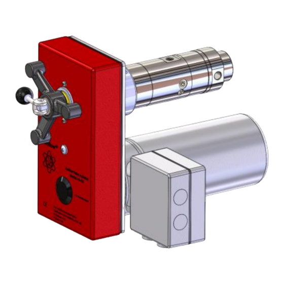
- Page 6 A6 Quick Start: H1 AMFLOW ® INSTALLATION Step 4 Prior to installing valve, confirm handle is in manual position. MANUAL MODE AUTOMATION MODE (Handle at Front) (Handle at Side) Copyright 2016 A & H Enterprises, Inc. © 00000329-0900-013 * Rev. A, 07/16 Page 6 of 17 All rights reserved...
-
Page 7: Installation: Valve
A6 Quick Start: H1 AMFLOW ® INSTALLATION Installation: Valve Step 1 Place FLANGE ADAPTOR onto VALVE STEM prior to installation. FLANGE ADAPTOR VALVE ADAPTOR LINK Step 2 Insert VALVE ADAPTOR LINK into FLANGE ADAPTOR. Place valve into BEARNG HOUSING. BEARING HOUSING VALVE ADAPTOR LINK Copyright... - Page 8 A6 Quick Start: H1 AMFLOW ® INSTALLATION Step 3 While valve is being inserted into BEARING HOUSING; rotate valve to align VALVE ADAPTOR LINK while handle is in manual mode. Step 4 Once properly aligned and engaged, tighten three (3) SETSCREWS to lock valve in place.
- Page 9 A6 Quick Start: H1 AMFLOW ® INSTALLATION Controls: Applicable to AM7E-001 Valve Only There are two controls used to operate the AM7E-001 flow control valve: The first control is the SWITCH by which the operator can select a high or low flow range. ...
-
Page 10: Wiring: H1
A6 Quick Start: H1 AMFLOW ® WIRING ACTUATOR WIRING: H1 Step 1 Provide 24VDC supply capable of providing up to 3 amps current. Step 2 Requires a minimum of 5 connections for H-1 operation. Step 3 Requires a minimum of 9 connections for set-up , Industrial Ethernet and H-1 communication. - Page 11 A6 Quick Start: H1 AMFLOW ® COMMUNICATIONS H1 COMMUNICATION SET-UP CAUTION Parameters are pre-set at the manufacturer. NOTE DHCP “Dynamic Hosting Configuration Protocol” is a method that automatically assigns IP addresses to devices connected to a network without manually configuring everything connected to a computer or server. Due to the wide variety of computers, networks, servers, routers and operating systems, a “DHCP”...
- Page 12 A6 Quick Start: H1 AMFLOW ® COMMUNICATIONS FOR FULL ACTUATOR INSTALLATION INSTRUCTIONS REFERENCE INSTALLATION & OPERATION MANUAL Copyright 2016 A & H Enterprises, Inc. © 00000329-0900-013 * Rev. A, 07/16 Page 12 of 17 All rights reserved...
- Page 13 A6 Quick Start: H1 AMFLOW ® CAUTION Caution CAUTION IMPROPER INSTALLATION AND START-UP MAY CAUSE DAMAGE VALVE INSTALLATION RECOMMENDATION Amflow ® valve should be connected to a “return to The purge port on an tank line” with a needle valve. This aids in the following: ...
- Page 14 A6 Quick Start: H1 AMFLOW ® CAUTION PROCEED with CAUTION This is very important, especially at high system pressures to prevent potential damage to seals and other internal components of valve. Step 4 VERY SLOWLY open Outlet Isolation Valve. Step 5 ...
-
Page 15: Safety Information
A6 Quick Start: H1 AMFLOW ® SAFETY Safety SAFETY INFORMATION Usage Use products only within range of pressure and temperature conditions indicated on product data sheet. Do not use with chemicals which are incompatible with 316SS or with seal materials. -
Page 16: Support
A6 Quick Start: H1 AMFLOW ® SUPPORT Support To order Amflow® products, spare parts or to receive assistance contact: ® A & H Enterprises, Inc. (Amflow +425.883.4040 ADDRESS CORRESPONDENCE TO: A & H Enterprises, Inc. 11812 NE 116 Street Kirkland, WA. 98033 E-mail: ah@amflow.com Fax: +425.823.1962... -
Page 17: Representatives
A6 Quick Start: H1 AMFLOW ® REPRESENTATIVES Representatives ® AMFLOW NORGE Norway, Sweden, Denmark, Netherlands, Germany, U.K., Italy Prinsens vei 12 4315 Sandnes Norway Telephone: +47.922.19.656 Fax: +47.520.00.591 E-mail: leif.egil.pettersen@amflow.no AMFLOW CONTROLS ASIA SDN. BHD. Malaysia, Indonesia, Singapore, India, Thailand, Vietnam No.
Need help?
Do you have a question about the AMFLOW A6 and is the answer not in the manual?
Questions and answers