Table of Contents
Advertisement
Quick Links
Amflow
INSTALLATION, OPERATION & SERVICE MANUAL
Reference the "As Built" data sheet supplied with order for specific actuator configuration.
A & H Enterprises, Inc. reserves the right to make modifications and/or improvements to
without prior notice.
DANGER AND/OR WARNING
The exclamation point within an equilateral triangle surrounded by red is intended to alert the user to the presence of
important operating and maintenance instructions that may cause personal injury or harm to the system.
CAUTION AND/OR IMPORTANT
The exclamation point within an equilateral triangle that is solid yellow with an exclamation point is intended to alert the user
to use caution or contains important information.
Copyright
2015 A & H Enterprises, Inc. All rights reserved
©
US & INTERNATIONAL PATENTS PENDING
®
11812 NE 116th Street
Kirkland, WA 98034 USA
AMFLOW
A2-ACM VALVE ACTUATOR
(BELT DRIVE)
Part Number: 00000222-0501
Explanation of Graphic Symbols
00000222-0904-000 * Rev. C, 09/15
A & H Enterprises, Inc.
www.amflow.com
EMAIL:
®
NOTE
TEL:
+425.883.4040
+425.823.1962
FAX:
ah@amflow.com
Amflow
®
products
Page 1 of 35
Advertisement
Table of Contents

Related Manuals for A & H AMFLOW A2-ACM

Summary of Contents for A & H AMFLOW A2-ACM
- Page 1 A & H Enterprises, Inc. Amflow ® 11812 NE 116th Street TEL: +425.883.4040 Kirkland, WA 98034 USA +425.823.1962 FAX: www.amflow.com ah@amflow.com EMAIL: INSTALLATION, OPERATION & SERVICE MANUAL AMFLOW ® A2-ACM VALVE ACTUATOR (BELT DRIVE) Part Number: 00000222-0501 NOTE Reference the “As Built” data sheet supplied with order for specific actuator configuration. Amflow ®...
-
Page 2: Table Of Contents
AMFLOW ® A2-ACM Installation, Operation & Service Manual TABLE OF CONTENTS SECTION 1: INFORMATION ......................................4 1.01 DESCRIPTION ........................................4 1.02 DESIGN FEATURES ......................................4 1.03 MECHANICAL FEATURES ....................................4 1.04 COMMUNICATION PROTOCOLS ..................................4 1.05 SAFETY INFORMATION ....................................5 1.06 ASSEMBLY VIEW ...................................... - Page 3 AMFLOW ® A2-ACM Installation, Operation & Service Manual TABLE OF CONTENTS SECTION 9: SERVICE: Pulley Assembly .................................. 29 9.01 REPLACEMENT: Bearing ....................................30 9.02 REPLACEMENT: Belleville Springs ................................. 30 9.03 REPLACEMENT: Pulley Belt ................................... 31 SECTION 11: TROUBLESHOOTING ................................... 32 11.01 No Power ........................................
-
Page 4: Section 1: Information
AMFLOW ® A2-ACM Installation, Operation & Service Manual INFORMATION SECTION 1: INFORMATION 1.01 DESCRIPTION ® Amflow A2-ACM Actuator is a DC gear driven motor actuator designed to accommodate a variety of ® Amflow products in hazardous area usage. Part compatibility includes; AM7 Series, AM8, AM11A flow control valves and the PR7 Series and PR-HF-SSSP back pressure regulators. -
Page 5: Safety Information
AMFLOW ® A2-ACM Installation, Operation & Service Manual INFORMATION 1.05 SAFETY INFORMATION SAFETY INFORMATION Follow IEC when working with electrical units. When handling product avoid dropping, damaging, or submerging. Ensure proper wiring. Person(s) handling circuit board should be properly grounded. ... -
Page 6: Assembly View: Transparent
AMFLOW ® A2-ACM Installation, Operation & Service Manual INFORMATION 1.07 ASSEMBLY VIEW: Transparent ® AMFLOW A2-ACM ACTUATOR Transparent View with Motor Housing ® AMFLOW A2-ACM ACTUATOR Transparent View with Motor Housing and Optional Cable Glands Copyright 2015 A & H Enterprises, Inc. All rights reserved ©... -
Page 7: Ga Drawing
AMFLOW ® A2-ACM Installation, Operation & Service Manual INFORMATION 1.08 GA DRAWING Copyright 2015 A & H Enterprises, Inc. All rights reserved © US & INTERNATIONAL PATENTS PENDING 00000222-0904-000 * Rev. C, 09/15 Page 7 of 35... -
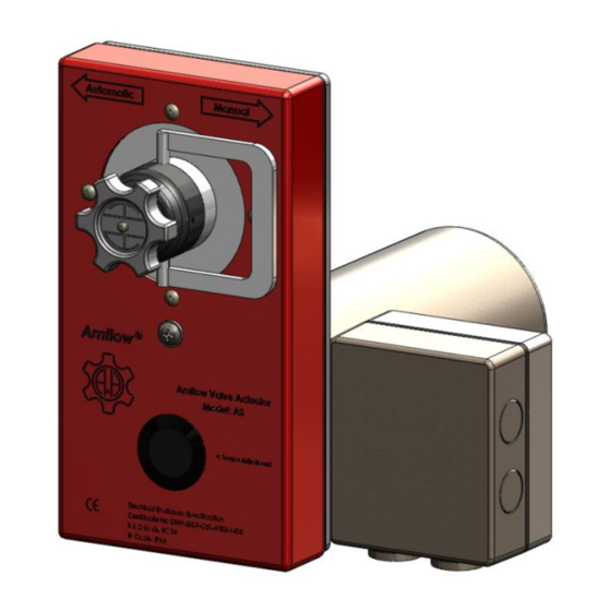
Page 8: Full View
AMFLOW ® A2-ACM Installation, Operation & Service Manual INFORMATION 1.09 FULL VIEW BASE PLATE FRONT GASKET CARRIER PULLEY Ex MOTOR HOUSING ASSEMBLY ASSEMBLY ADJUSTMENT HANDLE ASSY DC MOTOR KNOB MOTOR GASKET BELT ACM CIRCUIT BOARD EExe COVER RED COVER HOUSING EExe GASKET LINE BUSHINGS EExe CARRIER... -
Page 9: Cut-Away View: Belt Drive Assembly (Red Box)
AMFLOW ® A2-ACM Installation, Operation & Service Manual INFORMATION 1.10 CUT-AWAY VIEW: Belt Drive Assembly (Red Box) COVER HOUSING M4x8 PANHEAD SCREW BASE PLATE HANDLE SET SCREW ADJUSTMENT KNOB M3x10 PANHEAD SCREW BELLEVILLE SPRINGS PULLEY M4x8 PANHEAD SCREW M6x12 FLATHEAD M6x10 PANHEAD SCREW SCREW... -
Page 10: Exploded View: Belt Drive Assembly (Red Box)
AMFLOW ® A2-ACM Installation, Operation & Service Manual INFORMATION 1.11 EXPLODED VIEW: Belt Drive Assembly (Red Box) Copyright 2015 A & H Enterprises, Inc. All rights reserved © US & INTERNATIONAL PATENTS PENDING 00000222-0904-000 * Rev. C, 09/15 Page 10 of 35... -
Page 11: Bom: Belt Drive Assembly (Red Box)
AMFLOW ® A2-ACM Installation, Operation & Service Manual INFORMATION 1.11a BOM: Belt Drive Assembly (Red Box) ITEM # PART # DESCRIPTION 00000805-0501-000 A2-DCM Belt Drive Housing 00000254-0401-000 Carrier Assembly 1.1.1 00000241-0301-000 Carrier 1.1.2 00000243-0301-000 Carrier Ring 1.1.3 00000264-0401-000 Shaft Assy 1.1.3.1 00000262-0301-000 Shaft... - Page 12 AMFLOW ® A2-ACM Installation, Operation & Service Manual INFORMATION ITEM # PART # DESCRIPTION 00000822-0301-000 Carrier Gasket 00000256-0301-001 Cover Plug 00001500-7104-008-00 M4x8 Panhead 00000122-0301-000 Adjustment Knob 00001500-7103-010-00 M3x10 Panhead 1.11 00001500-8003-000-00 M3 Lockwasher 1.12 00000832-0401-000 Clutch Drive Shaft Assy 1.12.1 00000350-0401-000 Drive Pulley Assembly 1.12.1.1...
-
Page 13: Assembly View: Motor Housing Assembly
AMFLOW ® A2-ACM Installation, Operation & Service Manual INFORMATION 1.12 ASSEMBLY VIEW: Motor Housing Assembly BELL HOUSING EEx de CARRIER EXTERIOR DC MOTOR LINE BUSHINGS INTERIOR CIRCUIT BOARD DIN TERMINAL BLOCK Copyright 2015 A & H Enterprises, Inc. All rights reserved ©... -
Page 14: Exploded View: Motor Housing Assembly
AMFLOW ® A2-ACM Installation, Operation & Service Manual INFORMATION 1.12a EXPLODED VIEW: Motor Housing Assembly Copyright 2015 A & H Enterprises, Inc. All rights reserved © US & INTERNATIONAL PATENTS PENDING 00000222-0904-000 * Rev. C, 09/15 Page 14 of 35... -
Page 15: Bom: Motor Housing Assembly
AMFLOW ® A2-ACM Installation, Operation & Service Manual INFORMATION 1.12b BOM: Motor Housing Assembly ITEM PART DESCRIPTION 00000471-0401-000 EEx de Housing Assy 00000469-0301-000 EEx de Carrier 00000470-0301-000 Bell Housing 00000328-0301-000 Bearing 00000327-0301-000 Circlip 00000326-0301-000 Shaft Adaptor 00000473-0301-000 Motor Plate Adaptor 00001410-0401-001 DC Motor Assy w/Circuit Board 3.7.1... -
Page 16: Cut-Away View: Panel Mount
AMFLOW ® A2-ACM Installation, Operation & Service Manual INFORMATION 1.13 CUT-AWAY VIEW: Panel Mount FRONT of PANEL BACK of PANEL CUT-AWAY OF ® AMFLOW A2-ACM ACTUATOR PANEL MOUNT INSTALLATION CUT-AWAY OF ® AMFLOW A2-ACM ACTUATOR PANEL MOUNT INSTALLATION Shown without front cover and with ®... -
Page 17: Panel Mount: Cut-Out Dimensions
AMFLOW ® A2-ACM Installation, Operation & Service Manual INFORMATION 1.13a PANEL MOUNT: Cut-out Dimensions Mount A2-ACM Actuator using four 6 mm holes located on Ref. Diagram 1 (Item 1.3). BASE PLATE ASSEMBLY (Item 1.3) DIAGRAM 1: A2-ACM Actuator BASE PLATE ASSEMBLY END OF SECTION Copyright 2015 A &... -
Page 18: Section 2: Installation: Actuator
AMFLOW ® A2-ACM Installation, Operation & Service Manual INSTALLATION: Actuator SECTION 2: INSTALLATION: Actuator 2.01 INSTALLATION PRECAUTIONS Be careful when handling actuator, if dropped internal electronics may be damaged. Do not change manufacturer’s torque settings or unit may function incorrectly. ... -
Page 19: Installation Procedure: Actuator
AMFLOW ® A2-ACM Installation, Operation & Service Manual INSTALLATION: Actuator 2.04 INSTALLATION PROCEDURE: Actuator ® The fully assembled AMFLOW A2-ACM Actuator includes: (1) Belt Drive Assembly Ref. FIGURE 1 (1) EEx de Assembly Ref. FIGURE 2 FIGURE 1 FIGURE 2 Step 1 ... -
Page 20: Section 3: Installation: Valve
AMFLOW ® A2-ACM Installation, Operation & Service Manual INSTALLATION: Valve SECTION 3: INSTALLATION: Valve 3.01 VALVE INSTALLATION PRECAUTIONS Amflow ® Good system design is critical to the optimum operation of the Valves. At a minimum, the design should include: Amflow ®... -
Page 21: Section 4: Service: Valve Removal
AMFLOW ® A2-ACM Installation, Operation & Service Manual SERVICE: Valve Removal SECTION 4: SERVICE: Valve Removal BEFORE CARRYING OUT NEXT ACTIONS 1. Close down system or isolate valve to be removed. 2. Vent all pressure. 4.01 VALVE REMOVAL FROM SYSTEM Step 1 ... -
Page 22: Section 5: Service: Adjustments
AMFLOW ® A2-ACM Installation, Operation & Service Manual SERVICE: Adjustments SECTION 5: SERVICE: Adjustments 5.01 CHECK TORQUE Step 1 (Item 1.15). Unscrew and remove M6x10 FH SCREW Remove COVER HOUSING (Item 1.2) (Item 1.8). by removing all four (4) M4x8 PH SCREWS Step 2 ... -
Page 23: Torque Adjustment
AMFLOW ® A2-ACM Installation, Operation & Service Manual SERVICE: Adjustments 5.02 TORQUE ADJUSTMENT (if needed) Step 1 (Item 1.12.9): Using a 2.5mm Allen wrench, loosen M4x6 BH SCREW Adjust M4x10 FH SCREW (Item 1.12.8) located on front of clutch assembly. ... -
Page 24: Section 6: Service: Replacements - Gaskets
AMFLOW ® A2-ACM Installation, Operation & Service Manual SERVICE: Replacements SECTION 6: SERVICE: REPLACEMENTS - Gaskets 6.01 REPLACEMENT: Front Gasket Step 1 (Item 1.3). Remove BASE PLATE ASSEMBLY Step 2 (Item 1.1.11) (Item 1.3). Apply FRONT GASKET onto front of BASE PLATE ASSEMBLY ... -
Page 25: Replacement: Motor Gasket
AMFLOW ® A2-ACM Installation, Operation & Service Manual SERVICE: Replacements 6.02 REPLACEMENT: Motor Gasket Step 1 (Item 1.3). Remove BASE PLATE ASSEMBLY Step 2 (Item 1.3) Turn BASE PLATE ASSEMBLY over to the opposite of the side with laser markings, then; ... -
Page 26: Section 7: Service: Replacements
AMFLOW ® A2-ACM Installation, Operation & Service Manual SERVICE: Replacements SECTION 7: SERVICE: REPLACEMENTS 7.01 REPLACEMENT: Set Screw Step 1 (Item 1.3). Locate BASE PLATE ASSEMBLY Step 2 (Item 1.3) Turn BASE PLATE ASSEMBLY over to the opposite of the side with laser markings. ... -
Page 27: Section 8: Service: Clutch Drive Components
AMFLOW ® A2-ACM Installation, Operation & Service Manual SERVICE: Replacements SECTION 8: SERVICE: Clutch Drive Components 8.01 CLUTCH DRIVE: Disassembly & Replacement Step 1 (Item 1.12). Identify CLUTCH DRIVE ASSEMBLY Step 2 (Item 1.12.9). Using a 2.5mm hex wrench loosen M4x6 BH SCREW Step 3 ... - Page 28 AMFLOW ® A2-ACM Installation, Operation & Service Manual SERVICE: Replacements 8.01 CLUTCH DRIVE: Disassembly, continued Step 4 Remove parts in order: SPRING LOADER RETAINER (Item 1.12.3) Ref. FIGURE 1 SPRING LOADER (Item 1.12.4) Ref. FIGURE 2 BELLEVILLE SPRINGS (Item 1.12.5) (NOTE CONFIGURATION OF SPRINGS) Ref.
-
Page 29: Section 9: Service: Pulley Assembly
AMFLOW ® A2-ACM Installation, Operation & Service Manual SERVICE: Replacements SECTION 9: SERVICE: Pulley Assembly Step 1 (Item 1.2). Remove COVER HOUSING Step 2 Remove following parts in order: CARRIER CAP CARRIER CAP (Item 1.1.5) Ref. FIGURE 1 ... -
Page 30: Replacement: Bearing
AMFLOW ® A2-ACM Installation, Operation & Service Manual SERVICE: Replacements 9.01 REPLACEMENT: Bearing Step 1 (Item 1.1.9). Remove and replace BEARING(s) BEARING #1 BEARING #2 FIGURE 8 FIGURE 9 9.02 REPLACEMENT: Belleville Springs Step 1 (Item 1.1.15). Remove and replace BELLEVILLE SPRINGS ... -
Page 31: Replacement: Pulley Belt
AMFLOW ® A2-ACM Installation, Operation & Service Manual SERVICE: Replacements 9.03 REPLACEMENT: Pulley Belt Step 1 (Item 1.4). Remove old PULLEY BELT Step 2 (Item 1.4) (Item 1.1); Place new PULLEY BELT onto CARRIER ASSEMBLY then onto DRIVE PULLEY ASSEMBLY (Item 1.12.1). -
Page 32: Section 11: Troubleshooting
AMFLOW ® A2 ACM Installation, Operation & Service Manual TROUBLESHOOTING SECTION 11: TROUBLESHOOTING 11.01 No Power Issue: Actuator not responding. Cause: Blown fuse. Correction: Check and replace fuse. 11.02 Torque Slippage Issue: Valve not operating. Cause: Incorrect torque setting. Correction #1: Check that there is between 6.7 and 9 newton meters (60-80 in lbs.) rolling torque without PULLEY BELT slipping. -
Page 33: Standards & Certifications
AMFLOW ® A2 ACM Installation, Operation & Service Manual STANDARDS & CERTIFICATIONS STANDARDS A&H Enterprises designs its products to meet the applicable ASME, and API standards for valve design and pressure vessels. Products are also CE marked and ATEX approved for Hazardous area installations. MEMBERSHIPS CERTIFICATIONS ATEX DIRECTIVE (94/9/EC) -
Page 34: Limited Warranty
AMFLOW ® A2 ACM Installation, Operation & Service Manual WARRANTY LIMITED WARRANTY Amflow ® Each product is warranted to be free from defects in material and workmanship under normal use and service. The warranty period is three (3) years and begins on the date of original purchase. - Page 35 AMFLOW ® A2 ACM Installation, Operation & Service Manual REPRESENTATIVES ® AMFLOW NORGE Norway, Sweden, Denmark, Netherlands, Germany, U.K., Italy Prinsens vei 12 4315 Sandnes Norway Telephone: +47.922.16.656 Fax: +47.520.00.591 E-mail: leif.egil.pettersen@amflow.no AMFLOW CONTROLS ASIA SDN. BHD. Malaysia, Indonesia, Singapore, India, Thailand, Vietnam No.
Need help?
Do you have a question about the AMFLOW A2-ACM and is the answer not in the manual?
Questions and answers