Table of Contents
Advertisement
Quick Links
1. General
RF50 demo board is developed for RF50 chip (which is integrated MCU and RF circuit in single chip) to
demonstrating function, testing distance and debugging software.
2. Board characters
4 keys, UP key, DOWN key, ENTER key and RST key. RST key is used to reset MCU, the other 3 keys is
used to parameter setup and TX control. A piece of LCD is used to display the parameters and result of test.
3 indication LED, the first is power, the second is TX, the third is RX..
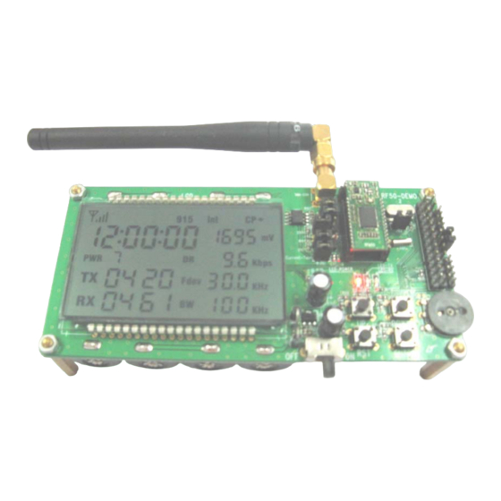
Power on, LCD display as follows:
RSSI RTC FREQ CLK AD compare RF50 antenna test port ISP UART
PWR DR FDEV BW power SW LEDTX LEDRX KEY VR101
3. A/D function
As top displaying, rotate the variable resistor(VR101)to adjust the input voltage of A/D port, the LCD
display 's A/D voltage result is change from 0 to 3300mV.
4. RTC function
As top displaying, can display and setup the current time, using 24 hour mode.
5. Compare function
As top displaying, rotate the variable resistor(VR101)to adjust the input voltage of A/D port, when the
input voltage higher than 1650mV (VDD/2) the LCD display "CP+", when lower than 1650mV(VDD/2) the
LCD display "CP_".
Tel: +86-755-82973805
Fax: +86-755-82973550
E-mail: sales@hoperf.com
RF50 Demo V1.1
http://www.hoperf.com
1
Advertisement
Table of Contents

Related Manuals for HopeRF RF50 Demo


Summary of Contents for HopeRF RF50 Demo
- Page 1 RF50 Demo V1.1 1. General RF50 demo board is developed for RF50 chip (which is integrated MCU and RF circuit in single chip) to demonstrating function, testing distance and debugging software. 2. Board characters 4 keys, UP key, DOWN key, ENTER key and RST key. RST key is used to reset MCU, the other 3 keys is used to parameter setup and TX control.
- Page 2 RF50 Demo V1.1 6. UART function Can transmit testing information, error information and received RF data to UART port. 7. Timer function In demo code have a 1ms timer. 8. Interrupt function This function is used in any other functions testing.
- Page 3 RF50 Demo V1.1 When press UP、DOWN、ENTER key on the other DEMO board to transmit RF data., this DEMO board’s RX LED will flash once if received data, then transmit the received data, the TX LED will flash once at the time.
- Page 4 RF50 Demo V1.1 11. Parameter setup When press ENTER key 2s on the board, it will work in setup mode and all setup items will flash. Then short press ENTER key, the board will enter next setup item by the order that frequence, MCU clock, hour, minute, second, power, data rate, Fdev, band width.
- Page 5 RF50 Demo V1.1 12. PCB picture Top view Bottom view SW101 Power switch, ON position turn on power J101 Current test J102 Must connect the jumper if RF transceiver is tested J103 Must connect the jumper if UART supply power J104,J105...
- Page 6 P1.5 R115 P0.7 P1.5 P0.6 P1.6 P0.6 P1.6 UART-PORT P-PORT P0.5 P1.7 P0.5 P1.7 VDD-3.3V COMPANY: P0.4 P2.0 P0.4 P2.0 HOPERF J103 P0.1 P2.1 P0.4 P2.7 P0.1 P2.1 P2.7 P0.3 P2.2 P0.3 P2.2 TITLE: VDD-3.3V D-VDD P0.2 P2.3 P0.2 P2.3 RF50/RFM50 DEMO P0.0...
Need help?
Do you have a question about the RF50 Demo and is the answer not in the manual?
Questions and answers