
Related Manuals for Xinuo HM-5818

Summary of Contents for Xinuo HM-5818
- Page 1 ECDIS (Electronic Chart Display and Information System) ◆ HM-5818( 19”24” ) User Manual ©1996-2020. Xinuo Information Technology (Xiamen) Corporation Limited...
-
Page 2: User Instructions
This manual is subject to change without notice. You can get the updates and the information on how to use or operate this product and others from www.xinuo.com, the website of Xinuo Information Technology (Xiamen) Corporation Limited. Warning: Please read the notes of this manual carefully to know about safety statements and other important information of products. -
Page 3: Notes
ECDIS User Manual Notes: Before starting the vessel borne navigation equipment, be sure to read following notes carefully to avoid product failures arising from improper operation: Please don’t place the vessel borne navigation equipment at random without fastening, in order that the equipment won’t be severely damaged when it falls off because of tossing or other factors during the navigation. -
Page 4: Table Of Contents
ECDIS User Manual Content User Instructions: ......................1 Notes: ..........................2 Content ..........................3 Chapter 1 ......................... 6 1.1 Product Descriptions ..................7 1.1.1 Hardware Components ................ 7 1.1.2 Host Interfaces ..................7 Chapter 2 ........................10 2.1 Home Screen ....................11 2.1.1 Description of Operational Interface ........... - Page 5 ECDIS User Manual 2.5.3 Moving objects ................... 32 2.5.4 Correcting the object ................33 2.5.5 Manually updates ................33 2.6 Mariners’ feature ..................... 33 2.7 Mariners’ Note ....................35 2.8 Navigation record ................... 35 2.9 AIS Information ....................36 2.9.1 AIS List .................... 37 2.9.2 Messages ...................
- Page 6 3.9.4 Update log ..................69 Chapter 4 ........................70 4.1 Equipment maintenance ................. 71 4.2 Operation Manual for HM-5818 Update Disk ..........72 4.2.1 Select boot device (If the default boot device is USB flash disk,you can skip this step) ....................72 4.2.2 Function Options ................
-
Page 7: Chapter 1
ECDIS User Manual Chapter 1 Overview In this chapter, an introduction is made to product appearances, accessories and keyboards. -
Page 8: Product Descriptions
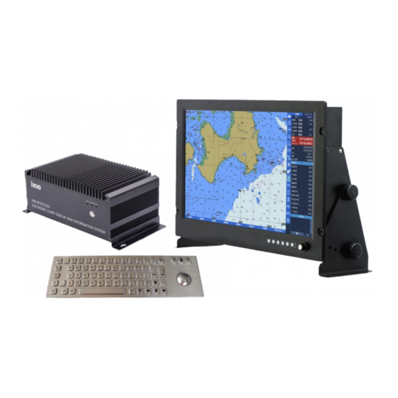
ECDIS User Manual 1.1 Product Descriptions HM-5818(19´24´) Electronic Chart Display and Information System (ECDIS) is controlled by the host and composed according to structures of displays with different size, to make it convenient to install the system and meet the needs for different display size. Its software system is operated on an open platform known as Linux, designed with functional modules. - Page 9 ECDIS User Manual...
- Page 10 ECDIS User Manual Model 2:...
-
Page 11: Chapter 2
Chapter 2 Operation and Setting This chapter will guide you to gradually become familiar with system operation and setting. -
Page 12: Home Screen
ECDIS User manual 2.1 Home Screen 2.1.1 Description of Operational Interface 1.Time display Setting the time by GPS. When there is no GPS signal, the user can adjust the time and time zone of the device to adjust the time. You can switch between world time and local time by clicking the time display button 2.Data information and standard abbreviation HDG: Heading of the vessel . - Page 13 ECDIS User manual LOG: Compass. GYRO: Gyro. DPT: depth sounder RADAR: Radar POSN GPS1: Position coordinates. GPS1 is the source of the signal. WGS 84: Benchmark 3.Cursor information 4.Display scale 5.Navigation monitoring Display basic information about route monitoring. Route Name: Displays the name of the currently monitored route. Yaw distance: The distance the vessel exceeds the safe distance and there is an alarm.
-
Page 14: Quick Operation Menu
ECDIS User manual Total time remaining: The time it takes for the vessel to arrive at the destination. Total remaining voyage: The remaining voyage at the end of the vessel . Planned speed: Shows the speed of use based on calculations in the voyage plan. Planned heading: Shows the current course of the vessel based on the route. - Page 15 ECDIS User manual mode. Select ,centered on the vessel 's position, as shown below: The specific information is displayed in the function window, as shown below. You can edit and modify the electronic bearing line by clicking the button on the window .The distance, azimuth, and reverse azimuth of the "relative center point"...
- Page 16 ECDIS User manual You can edit and modify the electronic bearing line by clicking the button on the window. The distance, azimuth, and reverse azimuth of the "relative center point" can be set manually. Display mode Click ,display mode switches in day 、...
- Page 17 ECDIS User manual signal detection Click , checks the status of the external signal access signal. When the signal status bar is green, the signal is normal, as shown in the figure: When the signal status is yellow, the signal is abnormal, as shown in the figure: System information ...
- Page 18 ECDIS User manual Click ,record a MOB position of the emergency landing point basing on the current position. The radar switch Click , you can quickly switch the radar icon display function. Light means the radar icon is turned on. Shortcut menu switch ...
-
Page 19: Route Design
ECDIS User manual 2.2 Route design 2.2.1 New route Click "New Route", move the cross cursor, click the left button to add a waypoint, and right click to end the route design. After adding the waypoints required for the route, click on the menu "Save Route"... -
Page 20: Deleting Waypoints
ECDIS User manual waypoint, click the left button, the waypoint is moved to the specified position of the cursor, right click to exit the edit waypoint operation. You can save the edited route by clicking the menu "Save Route" button. Click the left button above the route segment between the two waypoints to insert the waypoint. -
Page 21: Display Settings
ECDIS User manual Select the name of the route that needs to be deleted,and click the left button to pop up a prompt message asking if you want to delete the route. Click [YES] to delete the route and [No] to cancel deleting it. 2.2.6 Display Settings Click the "Display Settings"... -
Page 22: Loading The Route
ECDIS User manual Please follow the test results to modify this route. 2.2.8 Loading the route Click the “Load” button to pop up a list of all saved routes that are not displayed. Click one route in the list and the route information will be displayed in the route point list as shown: 2.2.9 Save the route If the currently selected route has not been saved or saved but has been modified, click the "Save "... -
Page 23: List Of Waypoints
ECDIS User manual 2.2.10 List of waypoints The route is loaded first, and the information of each waypoint of the route will be loaded into the waypoint list. The waypoint list shows the waypoint name, latitude and longitude, range type, range, safe distance, steering radius, and so on. Click the left mouse button to select the entire row, click the right mouse button to pop up the operation menu as shown: Select “Insert Waypoint”... -
Page 24: Voyage Schedule
ECDIS User manual the crew on this route. Double-click the Leg type unit to enter the voyage type edit, which pops up as shown: The calculation of the selection of the constant line voyage will be calculated according to the constant line, and the calculation of the voyage of the large circle will be calculated according to the route of the big circle. - Page 25 ECDIS User manual The planned route list consists of the waypoint name, estimated arrival time, stay, estimated departure time, estimated sailing time, total time, speed, and average speed. The waypoint name, estimated arrival time, stay, estimated departure time, and speed can be edited by the user.
-
Page 26: Route Export/Import
ECDIS User manual 2.2.12 Route Export/Import Click on the left column ,to export the route of the current device to the USB flash drive. Note that you will need to insert a USB flash drive at this time. When you choose to save, you need to select the correct USB address. -
Page 27: Settings
ECDIS User manual Click the shortcut key [Settings] on the right, select the “System” interface, and select the device in the system type to be ECDIS (Host) or ECDIS Backup (ECDIS Backup System). When the host and the backup system interact, view the interaction log, as shown in the following figure: 2.2.14 Settings The setting of the route design is to set the default values of the safety distance and the... -
Page 28: Route Monitoring
ECDIS User manual 2.3 Route monitoring Load a route, select “Monitoring”, the route monitoring window will appear in the right window, select “Start Monitoring”, the following window: After the selected route starts monitoring, you can view the detailed information of the route monitoring in the operation status bar, as shown in the figure: Among them, the estimated arrival time, the total remaining time, and the planned speed need to be set in the voyage schedule. -
Page 29: Electronic Chart Management
ECDIS User manual During the route monitoring process, all alarms, warnings, and prompts will give corresponding alarms in the alarm window in the lower right corner of the screen. As shown below: Among them, check the silence, the alarm will not sound an alarm. There is a corresponding alarm sound when the alarm is unchecked. -
Page 30: Chart Unit
ECDIS User manual 2.4.1 Chart unit Click on “Chart Cell” to view the detailed information of the chart files that have been installed in the current system, including chart unit name, chart type, scale, version number, update number, release date, update date, latitude and longitude range and other information. -
Page 31: Update Log
ECDIS User manual 2.4.3 Update log Click "Update Log" to view the update status of the current system chart, including update time, unit name, status, version number, update number, type, and whether abnormal prompts appear. 2.4.5 Data Service Provider At the top of the chart management window, you can select the chart data service provider to view the chart for the corresponding chart service provider. -
Page 32: New Object
ECDIS User manual object of the chart on the chart display (the orange mark is added below the object mark) as follows: Manually updated objects that users can add are added or edited or deleted by the object attributes of points, lines, and polygons. 2.5.1 New object In the "Object"... -
Page 33: Moving Objects
ECDIS User manual After clicking the "Delete" button, the system will confirm whether to delete again, the window is as follows: Click "Yes" to complete the deletion of the object. 2.5.3 Moving objects When you want to move the object, click the "Move" button to select the object to be moved on the chart. -
Page 34: Correcting The Object
ECDIS User manual to finish the object movement. 2.5.4 Correcting the object Select the "Modify" button and the cursor will automatically jump to the chart . Select the object to be corrected and click the left mouse ,as the following window: Edit the window based on the modified information. - Page 35 ECDIS User manual is selected firstly, as follows: Enter the settings, select " Mariners’ feature " in "Chart" and check " Mariners’ Note ". “Add Point”: Click “Add Point” and then go to the chart to select the specified position , press “OK”...
-
Page 36: Mariners' Note
ECDIS User manual press “OK” on different area to successfully add a certain area, press “Cancel” to pop up the edit box, and after editing, press “OK”. As shown below: 2.7 Mariners’ Note The crew note menu can be used to enter navigational notes and warnings information by the crew during the voyage. -
Page 37: Ais Information
ECDIS User manual The navigational record includes the current navigational record for the 12 hours and the navigational record for the last 3 months. Each record contains the recording time, location source, longitude, latitude, navigational heading, ship of heading, speed, unit, version number, update number, released date, updated date, and ENC source. -
Page 38: Ais List
ECDIS User manual 2.9.1 AIS List The AIS information window consists of AIS list and AIS details. The AIS list includes the number, MMSI, name (vessel name), distance from the vessel, speed, distance from the vessel , time of encounter, and distance met. You can click the header of the MMIS, distance, and speedometer items to sort the list. -
Page 39: Ais Navigation Parameter Settings
ECDIS User manual AIS lost alarm, alarms for active AIS and sleep AIS, the rang is from 1nm to 20nm. The specific parameters can be set according to the actual conditions. Filter sleeping AIS targets and AIS data reports, you can selected the type of AIS target and set the filtering conditions. -
Page 40: Ecdis Chart 1
ECDIS User manual shown below, after the radar display is turned on, all received radar icons and locations are displayed. Among them, when the radar button is lit, it indicates that the display is turned on. 2.11 ECDIS chart 1 According to the symbols in ECDIS chart 1, it can be used to query the comparison of objects on the chart. - Page 41 ECDIS User manual The ownship 's settings include ship vector, ship display style, own ship display settings,adjust ownship POSN manully, ownship information, initial position, etc. The ship vector refers to the vector line of the ship 's motion. The setting items include vector stabilization, time period, and time mark interval.
-
Page 42: System Settings
ECDIS User manual point of the bow line. The range from GPS to vessel is 1~ vessel length, GPS dstn to head to port is 1~ vessel width. Anchor to CCRP ver dstn and Anchor to CCRP hor dstn, which can be used for the GPS positioning reference of the anchor. - Page 43 ECDIS User manual 2) Choice of HDT: 3)Dead reckon function turned on or off 4) The track display setting can set whether to display the track or not and display the track interval as shown in the figure: 5) The language settings include Chinese and English as shown: 6) Cursor style selection is solid or hollow 7) North Reference Settings including True North and Magnetic north as shown: 8) Set the system a host or a backup system...
-
Page 44: Chart Setting
ECDIS User manual 11) System time calibration settings, you need to click OK after modifying the values, as shown: 12) Save the user's setting parameters, the user's personalized settings. This function is to satisfy different users to save the different parameter settings of the system. - Page 45 ECDIS User manual Point symbols: Includes simple symbols and traditional paper symbols. Depth shade: Includes two or four. You can set the contour line: Area boundary symbol: Includes symbolized and simplifies. Click the drop-down list to bring up the selection: Color scheme: including day, dusk, night.
- Page 46 ECDIS User manual Map language: Set the language of the map, including national language and English. Click on the drop-down list to bring up the selection: Select the national language, and the place names on the map are displayed in...
- Page 47 ECDIS User manual Chinese.Select English language, and the place names on the map are displayed in English. Position quality: displays the position accuracy symbol, and the question mark indicates that the object on the chart has insufficient geographic accuracy. Light sector lines: The scalloped fan line length of the beacon , when selected,the beacon would show the actual range by equal proportion, when unselected ,the beacon would show the range with a fixed length.
- Page 48 ECDIS User manual than the value set by the safety depth value, the system will automatically alarm to remind the driver. The chart objects are as follows: Basic display: The basic display of the chart includes the coastline (at high tide), the vessel 's safety and other deep lines, the display scale, and the north arrow.
-
Page 49: Sensor Settings
ECDIS User manual 2.12.4 Sensor Settings Sensor settings include GPS, AIS, compass, depth sounder, log, serial port, baud rate and master settings. Each input signal type is connected according to the corresponding port. After setting, click the “Apply” button to set the parameters to take effect. As Figure: First Model: Second Model:... -
Page 50: Alarm Settings
ECDIS User manual The baud rate can be set independently for each port. You can select the signal baud rate corresponding to the external connection line: 2.12.5 Alarm Settings The alarm setting includes navigation monitoring alarm, AIS encounter alarm setting, special condition area alarm setting Navigation monitoring alarms include destination alarms, route offsets, and safe distance and look-ahead time. - Page 51 ECDIS User manual When the vessel is approaching a special condition area during the voyage.,it would be alarmed.Special condition area containing as following: You can select the alarmed area according to the navigation needs, and the alarm will be automatically alarmed when the vessel approaches the selected area. Alarm priority: The alarm priority is setting the priority of the alarm.
-
Page 52: Network Settings
ECDIS User manual 2.12.6 Network Settings Access the VDR network interface. You can set the IP address according to the network segment. The following two columns can remain the same as the system and you do not need to change it. If you need to match the VDR, you can change the multicast address and port number to match the VDR. -
Page 53: Alarm Prompts And Responses
ECDIS User manual to the critical point when the key point on the route is less than the value set by the user. After accessing the AIS, the AIS will issue an AIS alarm when the AIS close to setting time and distance. -
Page 54: Lop Positioning
ECDIS User manual The record contains number, icon, occur time, alarm type, alarm content, response time, end time, etc., as shown in the figure: The alarm record can store the most recent 1000 alarms, and the system will automatically maintain these alarms. When the user acknowledges the alarm, the response time of the corresponding alarm will be updated. -
Page 55: How To Use
ECDIS User manual 2.14.2 How to use The following describes the use of two azimuth positioning lines to determine the position of the vessel . 1.The multi-function window selection displays the LOP positioning window as shown: 2.Left mouse click on the chart to select the position of the observation point or manually input the latitude and longitude at the latitude and longitude of the window;... - Page 56 ECDIS User manual 7.click bring up the Select Cross Point window as shown. The list in the window shows all the intersection positions. On the chart, the selected intersection points are drawn with big circles, and the positioning line becomes selected. 8.click ,set the reference point location and properties, as shown in Figure :...
-
Page 57: Distance And Position Calculation
ECDIS User manual Cancel: Close the position property window, the chart does not plot the intersection icon, and the positioning line becomes unselected; Application: The location property window is not closed, and the intersection icon is as shown in the figure; 9.click ,If during the estimation operation, the plot type changes from EP to DR, and the plot position is updated as the position to generate a log. - Page 58 ECDIS User manual as shown: Depth unit: Displays the water depth unit set in the system settings. Height unit: Displays the water depth unit set in the system settings. Water depth reference: The depth starting point in ocean measurements. Vertical datum: The starting point of the land elevation. Horizontal reference: The horizontal reference plane, usually WGS-84.
-
Page 59: Chapter 3
ECDIS User manual Chapter 3 Chart Installation This chapter will guide you to be gradually familiar with chart installation. -
Page 60: Summary
Click the scale on the head to arrange the charts in an ascending or descending order of scale. 3.4 IHO S-63 Data Protection Solution Xinuo ECDIS is compatible with IHO S-63 data protection solution (Version 1.2), with forward compatibility with Version 1.1. 3.5 SA Certificate... -
Page 61: Installation Of Sa Certificate
IHO and install it, in order to make sure that the SA certificate isn’t fake. The latest SA certificate has been installed on Xinuo ECDIS when it is released from the factory. You can view detailed information of the SA certificate in its dialog box, or you can log onto the official website of IHO to download and install the updated SA certificate by yourself. -
Page 62: Uninstall Sa Certificate
ECDIS User manual 3.5.2 Uninstall SA Certificate Click “uninstall certificate”, you will be reminded as follows: “Are you sure to uninstall the SA certificate?” If you click “Yes”, the SA certificate will be uninstalled from the system. You can click “No” to not to uninstall the certificate. After the SA certificate is uninstalled, no detailed information will be displayed. -
Page 63: Generate User Permit
3.7 Data Service Providers Xinuo ECDIS supports the simultaneous management of electronic chart exchange sets from multiple data service providers. Cell permit and product catalogue are classified according to data service providers, because following dialog boxes and pages exist for all... -
Page 64: Install Cell Permit
ECDIS User manual 3.8.1 Install Cell Permit Click “Install” and open the file dialog box. Choose the cell permit document named PERMIT.TXT and open it. If the format of a cell permit document is wrong, you will get following prompt: ... -
Page 65: Uninstall Cell Permit
ECDIS User manual 3.8.2 Uninstall Cell Permit Open the page of data service provider and switch to the page of cell permit. Choose a cell permit to be installed and click “uninstall”. Then, you will get a prompt: “Are you sure to uninstall the cell permit?” If you click “Yes”, the cell permit will be uninstalled from the system. -
Page 66: Install Exchange Set
ECDIS User manual Type (S-63 or S-57) State (expired, canceled, permitted, remain valid for less than 30 days) These words are only effective for S-63 electronic chart cells. For S-57 electronic chart cells, these words won’t exist. There are several states as follows: 1) Expired: A cell permit corresponding to an electronic chart cell has expired and become unsuitable for navigation. - Page 67 ECDIS User manual 1. Check the SA certificate 1) If SA certificate hasn’t been installed, following prompt will be given: “SSE 05-SA digital certificate (X509) is unavailable, and you can get the certificate from the official website of IHO or your data service provider.” Click “Yes”, and the installation is completed.
- Page 68 ECDIS User manual 5. Check if a cell permit has expired It the cell permit has been installed for corresponding electronic chart cell, the system will check the update date of the chart cell and expiry date of the cell permit. Besides, it will confirm if the expiry date of the cell permit is later than the update date.
-
Page 69: Install Map (S-57 Electronic Chart)
ECDIS User manual The updated product catalogue possibly exists in the canceled electronic chart cell. For each electronic chart cell that has been canceled, you will get the following prompt: “[CN302307] electronic chart cell has been canceled or won’t be updated any longer. -
Page 70: Update Log
ECDIS User manual As you click “uninstall”, a tooltip will pop up. If you click “Yes”, the chart will be uninstalled. Once you click “No”, the chart will not be uninstalled. 3.9.4 Update log Your previous records of installing, updating and uninstalling electronic chart units are saved by update log of electronic chart cells. -
Page 71: Chapter 4
ECDIS User manual Chapter 4 Equipment maintenance This chapter describes the maintenance and fault diagnosis equipment. -
Page 72: Equipment Maintenance
ECDIS User manual 4.1 Equipment maintenance Equipment can be easily replaced, the board does not need to repair fine recalibration or readjustment. Split device to monitor and control the host, display problems when replacement monitor, the new monitor is connected to the control panel can work without any recalibration or readjustment;... -
Page 73: Operation Manual For Hm-5818 Update Disk
4.2 Operation Manual for HM-5818 Update Disk The following steps would be for updating ECDIS application. Before you’re ready to update it, please make sure that you have the USB flash disk with latest Update Package. -
Page 74: Function Options
ECDIS User manual 4.2.2 Function Options After selected the USB flash disk, it would enter the menu of Update Package: 4.2.3 Update application When you enter the menu of Update Package, you can press ENTER key or wait for ... -
Page 75: Operation Manual For Hm-5818 System Rescue
ECDIS User manual At this time, you can remove your USB flash disk, and then press ENTER key. 4.3 Operation manual for HM-5818 system rescue The following steps would be for recovering ECDIS application & OS. You can follow the steps to do recovery when ECDIS was broken down or couldn’t boot up any more. -
Page 76: Function Options
ECDIS User manual 4.3.2 Function Options After selected the USB flash disk, it would enter the menu of System Rescue: Table 2 Description of options options Description General Recovery Recover application & OS. Advanced Options Warning: Advanced Options might make user data and [Professional User] installed ENC-charts lost. -
Page 77: General Recovery
ECDIS User manual Table 3 Description of advanced options Options Descriptions Clear User Data Clear user data, include system settings, planed routes, voyage record, manual updates information and so on. Clear Electrical Nautical Charts Clear the installed ENC-charts. Factory Recovery Recover ECDIS to the factory status, and it would clear user data and ENC-charts. -
Page 78: Advanced Options
ECDIS User manual 4.3.4 Advanced Options In some cases, after the recovery finished, ECDIS is still unavailable or not worked, it might be caused by broken data. If you retried General Recovery and failed again, you can try Advanced Options, such as Clear User Data, Clear Electrical Nautical Charts, Factory Recovery. -
Page 79: Annex I: Mounting Dimensions Of Host
ECDIS User manual Annex I: Mounting Dimensions of Host Mounting Dimensions of Display(19inch): Counter Mounting Flush Mounting... -
Page 80: Mounting Dimensions Of Display(24Inch)
ECDIS User manual Mounting Dimensions of Display(24inch): Counter Mounting Flush Mounting... -
Page 81: Annex 2
ECDIS User manual Annex 2: Specifications and Standards IEC 60945 Maritime Navigation and Radio-communication Equipment and Systems - General Requirements - Methods of Testing and Required Test Results, ed4.0, 2002 IEC 61162-1 Maritime Navigation and Radio-communication Equipment and Systems - Digital Interface - Part 1: Single-transmitter and Multiple-receiver, ed4.0, 2010 IEC 61162-2 Maritime Navigation and Radio-communication Equipment... - Page 82 ECDIS User manual CCS GDXXX_2012 Test Guideline for ECDIS No. 266 Circular Memorandum of the IMO Maritime Safety Committee about Display of Electronic Charts and Software Maintenance of Information System...
- Page 83 Xinuo Information Technology (Xiamen) Corporation Limited Address: Unit 2001, 1 Chengyi North Street (B04), Software Park III, Xiamen, China TEL: (86) 592-3300300 FAX: (86) 592-3300310 Http://www.xinuo.com Email: info@xinuo.com Service Hotline: 400-8868-592 190410-ECDIS...
Need help?
Do you have a question about the HM-5818 and is the answer not in the manual?
Questions and answers