
Subscribe to Our Youtube Channel
Related Manuals for Sommer & Maca Industries VFE-4

Summary of Contents for Sommer & Maca Industries VFE-4
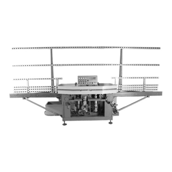
- Page 1 VFE-4 FOUR-CUP FLAT EDGER 5501 West Ogden Avenue Cicero, Illinois 60804 Tel: (708). 863.5446 / (773). 242.2871 Fax: (708). 863.5462 ATLANTA / CICERO / COMMERCE / DALLAS / MOONACHIE/ SANTA CLARA Sommer & Maca Industries, Inc.
-
Page 2: Warranty Statement
WARRANTY STATEMENT SOMMER & MACA Industries, Inc. (Seller) warrants products of its manufacture to be free from defects in materials and workmanship in normal use for six months from the date of shipment unless a shorter period is provided elsewhere in this document. Seller’s obligation and Buyer’s exclusive remedy shall be limited to the repair or replacement at Seller’s option, of defective parts within warranty period, provided Buyer gives Seller immediate written notice of such alleged defects, and if requested by Seller, returns the defective parts to Seller’s factory for Seller’... - Page 3 PREFIX We suggest to carefully follow the instructions in this manual and to regularly follow procedures of maintenance, which will allow you to obtain a higher degree of reliability, safety and durability of the product. This manual contains several advises and precautions for safety. We urge you to read them carefully. In this way you will avoid danger, injuries and eventual damage to the machine.
- Page 4 INDEX Technical features 1.1) Machine dimensions 1.2) Electrical and pneumatic requirements 1.3) Machine performance description Safety rules 2.1) General safety rules Shipping, movement and storage 3.1) Machine shipping and crating 3.2) Packing and unpacking 3.3) Storage until installation Installations and connections 4.1) Environmental working conditions 4.2)
-
Page 5: Technical Features
TECHNICAL FEATURES 1.1) Machine dimensions Length 5000 mm (196.5”) Width 1300 mm (51”) Total height 2400 mm (94.5”) Worktop height 850 mm (33.5”) Weight 1300 Kg (2866.5 lbs) 1.2) Electrical and pneumatic requirements Voltage 3-Phase/230Volts +/- 10% Frequency 60 Hz. +/- 5% Auxiliary service voltage 24Volts/60Hz. -
Page 6: Safety Rules
SAFETY RULES The machine is provided with all devices of protection both mechanical (chain guard, shelters, etc.) and electrical (sensors, stops, etc.) in order to avoid any contact with moving parts by the operator. It is absolutely prohibited for anyone to alter or remove any safety devices mentioned above with the power on!! Any kind of verification, control, cleaning, maintenance, change or substitution of parts must be done with the power off and the main disconnect locked out. - Page 7 SHIPPING, MOVEMENT AND STORAGE Specialized and competent personnel must perform all shipping operations of the machine. 3.1) Machine shipping and crating The crated machine is easily transportable by a crane or a forklift with a minimum capacity of (3) tons and lifting eyes as shown on the machine assembly drawing in the Annex 0 section of this manual.
-
Page 8: Installation And Connections
INSTALLATION AND CONNECTIONS 4.1) Environmental working conditions. The machine can work at temperatures between 41 and 113 degrees Fahrenheit. 4.2) Space requirements Make sure that the clearance provided around the machine is sufficient to be able to open all doors completely and to perform all operations of maintenance. -
Page 9: Equipment Description
EQUIPMENT DESCRIPTION There are four spindles equipped with: • diamond grinding wheel – 150 mm dia. (M1) • grinding wheel for rear arris – 100 mm dia. (M2) • grinding wheel for front arris – 100 mm dia. (M3) • polishing wheel for flat edge –... -
Page 10: Main Assemblies
MAIN ASSEMBLIES 1) Lever to regulate glass removal 2) Dial indicator for reading of quantity to be removed 3) Adjustable feet to level the machine 4) Knurled knob for diamond grinding wheel adjustment 5) Diamond grinding wheel motor M1 6) Rear arris grinding wheel motor M2 7) Front arris grinding wheel motor M3 8) Polish wheel motor M4 9) Pneumatic cylinder... - Page 11 OPERATION CYCLE: COMMANDS AND FUNCTIONS The machine operator is advised to do the following: Warning: Always make sure the pump is ON, before you run glass. Otherwise a major damage could be caused to the machine. The switching on of the spindles must be done progressively as follows: 1.
- Page 12 7.1) Wheel replacement procedure When replacing grinding or polish wheels, insert spindle-locking wrench over the flats on the spindle hub. Place 30mm box wrench or 8mm Allen wrench on the spindle locking screw, hold firm and rotate the spindle clockwise. This will loosen locking screw. Reverse hub rotation to tighten locking screw. In the event you must replace the diamond grinding, proceed as follows: •...
- Page 13 MACHINE CIRCUITS 8.1) Electric circuit ♦ Schematic and components annex #2 ♦ Control panel annex #1 8.2) Electrical specification General electrical characteristics Machine voltage 3 phase/230 volts +/-10% Frequency of operation 60 Hz +/-5% Auxiliary service voltage 24 volts/60 Hz ...
-
Page 14: Maintenance
MAINTENANCE WARNING! Any kind of verification, cleaning, maintenance, replacement and substitution of parts must be performed with the power off and the main disconnect locked out. (see section 2) OSHA 29 CFR 1910.147 standard requires the placement of a lockout on energy stored equipment in a manner that will render them safe to work on and prevent the inadvertent start up of such equipment, in accordance with an established procedure, and ensure that the energy-isolating device and... -
Page 15: Troubleshooting Solutions
10.) TROUBLE SHOOTING SOLUTIONS PROBLEM CAUSE SOLUTION Motors do not spin Burnt fuse Replace Thermal out Reset Electrical interruption Verify No pneumatic movement Not enough air pressure Verify pressure At 6 bars / 90 psi. Minimum Solenoid valve broken Check and replace or defective Water pump not working Burnt fuse... - Page 16 11.) ANNEXES Main Assembly Annex#0 Control panel Annex #1 Electrical circuit outline Annex #2 Pneumatic circuit outline Annex #3 Assemblies Annex #4 Programming of “Mini-Job” Controller Annex #5 ...
- Page 17 ANNEX #0...
- Page 19 ANNEX #1...
- Page 21 ANNEX #2...
- Page 31 ANNEX #3...
- Page 33 ANNEX #4...
- Page 43 ANNEX #5...
- Page 44 Programming of “Mini-Job” Controller Caution: Parameters have been factory set. Changes to these settings without consulting supplier may void warranty. The procedure for making program or parameter changes of the distance settings from the glass micro switch are as follows: 1.
Need help?
Do you have a question about the VFE-4 and is the answer not in the manual?
Questions and answers