
Subscribe to Our Youtube Channel
Related Manuals for Sigma Controls 700 Series

Summary of Contents for Sigma Controls 700 Series
- Page 1 700 SERIES ‘MM’ MOTOR MONITOR INSTRUCTION MANUAL VISIT OUR WEBSITE SIGMACONTROLS.COM 700 MM MANUAL 042414...
-
Page 2: Table Of Contents
TABLE OF CONTENTS INTRODUCTION………………………………………… Ordering Information Specifications Features WIRING…………………………………………………… Dwg # 12-103 (700 MM Motor Monitor) Showing: Inputs (8) 100 OHM RTD Digital Output (4) Form ‘C’ Relays PROGRAMMING AND INITIAL SETUP……………... Input Range Selection Terminal Block Detail Initial Setup & Programming Overview/Key Description DIAGNOSTICS……………………………………………... -
Page 3: Introduction
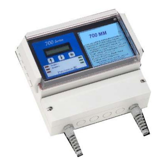
INTRODUCTION: The Sigma 700 Series ‘MM’ Motor Monitors are state of the art microprocessor based, user configurable instruments for the monitoring and alarming of embedded temperature probes in electric motor windings and bearings. The 700 Series float controllers perform the following functions. - Page 4 POWER: 24VDC, (110VAC optional) ENVIRONMENTAL: Operating, 0-65° C Storage, -40° -80° C R.H., 0-90% non condensing ENCLOSURE: ¼ DIN, ABS plastic 96 X 96 X 110MM or Nema 4X wall mount FRONT PANEL: Gasketed Nema 4X Hinged Window TERMINAL STRIP: (24) Removable for ease of wiring 28 –...
-
Page 5: Features
FEATURES: Microprocessor Based LCD Display 3 Function Keys Isolated 24VDC Sensor Power (with 110VAC option) 4 Form ‘C’ Relay Outputs Fully User Programmable in English ® 1 Ea. RS485 Port (Programming and SCADA) MODBUS Master/Slave. CPU Activity Monitor WIRING DETAIL See Dwg # 12-103 All electrical wiring must be in accordance with all local state and national codes that apply. - Page 7 PROGRAMMING & SETUP Review Screens The 700 Series MM utilizes ‘plain English’ menu driven screens which are sequential and intuitive. When the unit powers up, the startup screen will appear as follows: Software Version # Identifies the unit Function and Version # After the initial screens have appeared, the unit will show the ‘MAIN SCREEN’...
- Page 8 PROGRAMMING SCREENS From the Main Menu, Press the button to access the Password Screen: Use the buttons to enter the preprogrammed password, then press to advance to the Menu Screens. Use the buttons to advance to the ‘Scaling’ screen. NOTE: Since the unit is designed for a fixed range sensor scaling is automatic. However due to inconsistencies in some sensors a ‘TWEAK’...
- Page 9 This completes the ‘Scaling’ section. Press to save any changed values and return to the ‘Main Menu’ Screen. As previously described, enter the MENU selection and select the ‘SETPOINTS’ menu, where process setpoints are entered. The first screen is the bearing warning setpoint. This is the temperature which brings up the ‘HOT’...
- Page 10 ADVANCE TO THE ‘SETUP’ MENU’ Setup screen provides ‘global’ parameters which affect overall performance and operation. PASSWORD SCREEN Setting a password ‘Locks’ out unauthorized access to program items. NOTE: Please make a note of the password value if changed. Access to the Menus will be unavailable without the correct password.
- Page 11 Press to advance to the log interval time settings. NOTE: This screen allows for setting the log interval. As shown the unit will take a reading every 5 seconds. Logging may also be started and stopped by connecting a dry contact between DI1 and digital common.
-
Page 12: Programming Record Sheet
SERIES 700 MOTOR MONITOR PROGRAMMING RECORD SHEET Model Number: ________________ Serial Number: _________________ Version: ________________ • Scaling: Phase C1 Tweak ___________ Phase A1 Tweak _________ Phase C2 Tweak ___________ Phase A2 Tweak _________ Bearing 1 Tweak ___________ Phase B1 Tweak _________ Bearing 2 Tweak ___________ Phase B2 Tweak _________ •... - Page 13 MAINTENANCE AND TROUBLE SHOOTING The Series 700 MM is a digital solid state device which requires no periodic maintenance. Occasional checks of the unit should be carried out for physical and mechanical security of mounting, terminal blocks, and electrical wiring. TROUBLE SHOOTING •...
-
Page 14: Warranty
WARRANTY All Sigma Controls, Inc. products are warranted to be free from defective materials and workmanship for one (1) year from date of shipment. Sigma reserves the right to repair or replace at its option any product found to be defective.
Need help?
Do you have a question about the 700 Series and is the answer not in the manual?
Questions and answers