Table of Contents
Advertisement
Quick Links
Advertisement
Chapters
Table of Contents

Related Manuals for Charles Machine Works Ditch Witch RT125

Summary of Contents for Charles Machine Works Ditch Witch RT125
- Page 1 RT125 Operator’s Manual Issue 2.1 053-2942 Original Instruction...
-
Page 2: Table Of Contents
RT125 Operator’s Manual Overview - 1 Overview Chapter Contents Serial Number Location ..... . 2 Intended Use ....... 3 Equipment Modification . -
Page 3: Serial Number Location
RT125 Operator’s Manual Overview - 2 Serial Number Location Serial Number Location Record serial numbers and date of purchase in spaces provided. RT125 (1) and engine serial numbers (2) are located as shown. Date of manufacture Date of purchase RT125 serial number Front attachment serial number Rear attachment serial number Trailer serial number... -
Page 4: Intended Use
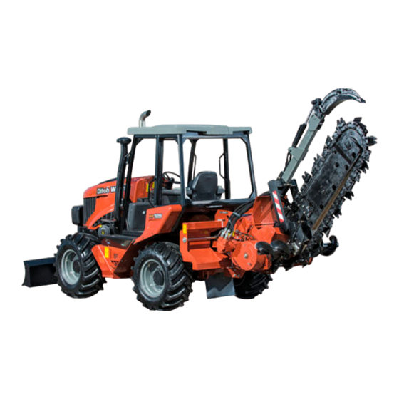
RT125 Operator’s Manual Overview - 3 Intended Use Intended Use The RT125 is a riding trencher designed to install buried service lines of various sizes using a variety of ® Ditch Witch attachments. Attachment* Max. width/diameter Max. depth BH120 backhoe 24”... -
Page 5: Unit Components
RT125 Operator’s Manual Overview - 4 Unit Components Unit Components 1. Rollover Protective Structure (ROPS) 4. Engine compartment 2. Operator station 5. Backfill blade (optional) 3. Control consoles... -
Page 6: Operator Orientation
RT125 Operator’s Manual Overview - 5 Operator Orientation Operator Orientation 1. Front of unit 3. Rear of unit 2. Right of unit 4. Left of unit Right and left sides of machine are determined by facing front of unit while seated at the controls. t50om008w.eps About This Manual This manual contains information for the proper use of this machine. - Page 7 RT125 Operator’s Manual Overview - 6 About This Manual...
-
Page 8: Foreword
If you need a replacement copy, contact your Ditch Witch dealer. If you need assistance in locating a dealer, visit our website at www.ditchwitch.com or write to the following address: The Charles Machine Works, Inc. Attn: Marketing Department PO Box 66 Perry, OK 73077-0066 The descriptions and specifications in this manual are subject to change without notice. - Page 9 Issue number 2.1/OM-06/17 Part number 053-2942 Copyright 2016, 2017 by The Charles Machine Works, Inc. and Ditch Witch are registered trademarks of The Charles Machine Works, Inc. This product and its use may be covered by one or more patents at http://patents.charlesmachine.works.
- Page 10 RT125 Operator’s Manual Contents - 9 Contents Overview machine serial number, information about the type of work this machine is designed to perform, basic machine components, and how to use this manual Foreword part number, revision level, and publication date of this manual, and factory contact information Safety machine safety alerts and emergency procedures...
- Page 11 RT125 Operator’s Manual Contents - 10 Plow procedures for plowing Drill procedures for drilling Systems and Equipment chain, teeth, sprockets, and optional equipment Complete the Job procedures for backfilling and restoring the jobsite and rinsing and storing equipment Service service intervals and instructions for this machine including lubrication, replacement of wear items, and basic maintenance Specifications machine specifications including weights, measurements, power ratings, and fluid...
-
Page 12: Safety
RT125 Operator’s Manual Safety - 11 Safety Chapter Contents Guidelines ....... . 12 California Proposition 65 Warning . -
Page 13: Guidelines
RT125 Operator’s Manual Safety - 12 Guidelines Guidelines When you see this safety alert sign, carefully read and follow all instructions. YOUR SAFETY IS AT STAKE. Read this entire section before using your equipment. Follow these guidelines before operating any jobsite equipment: •... -
Page 14: Emergency Procedures
RT125 Operator’s Manual Safety - 13 Emergency Procedures Emergency Procedures Jobsite hazards could cause death or serious injury. Use correct equipment and work methods. Use and maintain proper safety equipment. Before operating any equipment, review emergency procedures and check that all safety precautions have been taken. -
Page 15: If An Electric Line Is Damaged
RT125 Operator’s Manual Safety - 14 Emergency Procedures If an Electric Line is Damaged If you suspect an electric line has been damaged and you are on tractor, DO NOT MOVE. Remain on tractor and take the following actions. The order and degree of action will depend upon the situation. •... -
Page 16: If A Gas Line Is Damaged
RT125 Operator’s Manual Safety - 15 Emergency Procedures If a Gas Line is Damaged Fire or explosion possible. Fumes could ignite and cause burns. No smoking, no flame, no spark. 275-419 (2P) Explosion possible. Serious injury or equipment damage could occur. Follow directions carefully. -
Page 17: If A Fiber Optic Cable Is Damaged
RT125 Operator’s Manual Safety - 16 Emergency Procedures If a Fiber Optic Cable is Damaged Do not look into cut ends of fiber optic or unidentified cable. Vision damage can occur. Contact utility company. If Machine Catches on Fire Perform emergency shutdown procedure and then take the following actions. The order and degree of action will depend on the situation. -
Page 18: Safety Alert Classification
RT125 Operator’s Manual Safety - 17 Safety Alert Classifications Safety Alert Classifications These classifications and the icons defined on the following pages work together to alert you to situations which could be harmful to you, jobsite bystanders or your equipment. When you see these words and icons in the book or on the machine, carefully read and follow all instructions. -
Page 19: Machine Safety Alerts
RT125 Operator’s Manual Safety - 18 Machine Safety Alerts Machine Safety Alerts Hot parts may cause burns. Do not touch until cool or wear gloves. 275-355 (2-P), 273-423 (2-P) Rollover could kill or crush. Wear seat belt. 275-303 Read operator’s manual. Follow safety rules and know how to use all controls. - Page 20 RT125 Operator’s Manual Safety - 19 Machine Safety Alerts Tiedown location. See Transport chapter for more information. 274-318 Fall possible. Riders can fall from machine and be injured or killed. Single operator only. 275-185 Fire or explosion possible. Do not use starter fluid. 273-459 (2P), 274-206 (2P), 700-206 (2P)
- Page 21 RT125 Operator’s Manual Safety - 20 Attachment Safety Alerts Attachment Safety Alerts BH120 ‘ Moving parts could cut off hand or foot. Stay away. 275-184, 273-437, Crushing weight could cause death or serious injury. Stay away. 275-326, 701-326...
- Page 22 RT125 Operator’s Manual Safety - 21 Attachment Safety Alerts CT120H Tiedown location. See Transport chapter for more information. 274-318 Moving digging teeth can kill. Trench cave-in can 6ft/2m cause you to fall. Stay away. 275-097, 270-6900 DANGER stripe decal. See Parts Manual for replacement part numbers.
- Page 23 RT125 Operator’s Manual Safety - 22 Attachment Safety Alerts ST120H Tiedown location. See Transport chapter for more information. 274-318 Moving digging teeth can kill. Trench cave-in can 6ft/2m cause you to fall. Stay away. 275-097, 274-002 Moving parts could cut off hand or foot. Stay away. 275-184, 273-546 DANGER stripe decal.
- Page 24 RT125 Operator’s Manual Safety - 23 Attachment Safety Alerts PT120H Moving digging teeth can kill. Trench cave-in can 6ft/2m cause you to fall. Stay away. 275-097, 274-002 Crushing weight could cause death or serious injury. Stay away. 275-326, 701-326 DANGER stripe decal. See Parts Manual for replacement part numbers.
- Page 25 RT125 Operator’s Manual Safety - 24 Attachment Safety Alerts RC30 Crushing weight could cause death or serious injury. Stay away. 275-326, 701-326...
- Page 26 RT125 Operator’s Manual Safety - 25 Attachment Safety Alerts RS40 Flying objects thrown by machine may strike people. Wear safety glasses and hard hat. 275-193 Moving digging teeth will cause serious injury or death. Stay away. 275-443, 275-103 ‘ Moving parts could cut off hand or foot. Stay away. 275-184, 273-437,...
- Page 27 RT125 Operator’s Manual Safety - 26 Attachment Safety Alerts VP120H Tiedown location. See Transport chapter for more information. 274-318 Crushing weight could cause death or serious injury. Stay away. 275-326, 701-326 ‘ Moving parts could cut off hand or foot. Stay away. 275-184, 273-437,...
- Page 28 RT125 Operator’s Manual Safety - 27 Attachment Safety Alerts RWIII/RWIV Turning shaft will kill you or crush arm or leg. Stay away. 275-197...
- Page 29 RT125 Operator’s Manual Safety - 28 Attachment Safety Alerts...
-
Page 30: Controls
RT125 Operator’s Manual Controls - 29 Controls Chapter Contents Center Console ......30 Right Console . -
Page 31: Center Console
RT125 Operator’s Manual Controls - 30 Center Console Center Console 1. Auxiliary outlet 4. Steering column tilt control 2. Ground drive foot control 5. Ground drive direction/speed control 3. Brake pedal Item Description Notes 1. Auxiliary outlet Provides power for other Power output is 12V, 10A. - Page 32 RT125 Operator’s Manual Controls - 31 Center Console Item Description Notes 2. Ground drive foot To move tractor, push pedal To function, ground drive direction control down. control must be in forward or reverse. See “Ground drive direction/speed To increase speed in either control”...
-
Page 33: Right Console
RT125 Operator’s Manual Controls - 32 Right Console Right Console t48om004w.eps 1. Horn button 9. Start override button 2. Ignition switch 10. Rear steer mode selector switch 3. Plow lift control 11. Rear steer adjustment switch* 4. Plow swing control 12. - Page 34 RT125 Operator’s Manual Controls - 33 Right Console Item Description Notes 2. Ignition switch To start engine, insert key and turn clockwise. To stop engine, turn counterclockwise. c00ic137w.eps 3. Plow lift control To lower, move forward. NOTICE: To raise, pull back. •...
- Page 35 RT125 Operator’s Manual Controls - 34 Right Console Item Description Notes 6. Saw lift/Trencher lift To lower, move forward. control To raise, pull back. c00ic209h.eps To lower, move forward. To raise, pull back. 7. Saw stabilizer control To lower, move forward. To raise, pull back.
- Page 36 RT125 Operator’s Manual Controls - 35 Right Console Item Description Notes 10. Rear steer mode To engage rear steer, press selector switch left. To center wheels, press right. c00ic146w.eps 11. Rear steer adjustment To move rear wheels left, NOTICE: Visually verify wheel switch press and hold left.
- Page 37 RT125 Operator’s Manual Controls - 36 Right Console Item Description Notes 14. Reel winder/Backfill Backfill blade mode: blade control • To lower, move forward. • To raise, move backward. • To tilt right side down, move right. • To tilt left side down, move left.
-
Page 38: Graphic Display
RT125 Operator’s Manual Controls - 37 Graphic Display Graphic Display Gauges and Indicators 1. Tachometer 8. Rear steer indicator 2. Engine speed display (rpm) 9. Ground drive direction indicator 3. Real time clock 10. Backfill blade float indicator 4. Cruise control set speed display (rpm) 11. - Page 39 RT125 Operator’s Manual Controls - 38 Graphic Display Item Description Notes 3. Real time clock Displays time. 4. Cruise control set Displays numeric value for Only shown when cruise selector speed display (rpm) speed if cruise control is set. switch is ON. See “Cruise control selector switch”...
- Page 40 RT125 Operator’s Manual Controls - 39 Graphic Display Item Description Notes 13. Parking brake indicator Lights when parking brake is set. 14. Axle lock indicator Lights when axle lock is set.
- Page 41 RT125 Operator’s Manual Controls - 40 Graphic Display Gauges and Indicators 1. Hydraulic fluid temperature indicator 7. Aftertreatment service indicator 2. Hydraulic fluid filter indicator 8. High exhaust temperature indicator 3. Engine caution/stop indicator 9. Voltmeter display 4. Fuel gauge 10.
- Page 42 RT125 Operator’s Manual Controls - 41 Graphic Display Item Description Notes 2. Hydraulic fluid filter Lights when hydraulic filter is NOTICE: Engine caution indicator will indicator restricted. light when hydraulic fluid filter needs attention. See “Engine caution/stop indicator” on page 41. 3.
- Page 43 RT125 Operator’s Manual Controls - 42 Graphic Display Item Description Notes 11. Engine coolant Displays engine coolant Normal coolant temperature is 187°- temperature indicator/ temperature. 230° F (86°-107° C). numeric display 12. Engine oil pressure Displays engine oil pressure. Minimum pressure for warm engine at indicator/numeric full throttle is 32 psi (2.25 bar).
-
Page 44: Buttons
RT125 Operator’s Manual Controls - 43 Graphic Display Buttons 10:10 10:10 15 5 X100 X100 1938 1938 1500 1500 1750 1750 12.2 12.2 Volts Volts Hours Hours t48om052w.eps 1. Hide/Recall engine diagnostics key 3. Main menu key 2. Day/Night mode key Item Description Notes... - Page 45 RT125 Operator’s Manual Controls - 44 Graphic Display Main Menu t48om058w.eps 1. System settings key 5. User settings key 2. Exhaust cleaning activation key 6. Return key 3. Machine diagnostics code display key 7. Air filter restriction indicator 4. Brightness control display key Press the center soft key to display the main menu screen, which has icons for other functions.
- Page 46 RT125 Operator’s Manual Controls - 45 Graphic Display Item Description Notes 4. Brightness control Press to change the Minimum brightness is 10%. display key brightness of the display Maximum brightness is 100%. screen. 5. User settings key Press to customize settings. Real time clock setting, unit setting, and language can be changed in this screen.
- Page 47 RT125 Operator’s Manual Controls - 46 Graphic Display Diagnostic Messages Diagnostic Message: 3 of Gearbox oil temperature; Short circuit to ground SPN: 523618 FMI: 4 DID: t48om048w.eps 1. Hide/Recall key 3. Next error message key 2. Diagnostics error message information display 4.
- Page 48 RT125 Operator’s Manual Controls - 47 Graphic Display Display Pop-Up Messages Machine display will automatically display pop-up messages for start interlock and exhaust cleaning systems when needed. Display screen will return to normal once conditions are met. Start Interlock For machine to start, operator must be in seat and ground drive direction control must be in neutral. If one or more of these conditions is not met, a pop-up message will appear with applicable information about which condition is not met.
-
Page 49: Left Console
RT125 Operator’s Manual Controls - 48 Left Console Left Console 1. Reel winder selector switch 6. Cruise control speed dial control 2. Reel carrier lift control 7. Cruise control selector switch 3. Gearbox shift control 8. Attachment speed/direction control 4. Axle lock switch 9. - Page 50 RT125 Operator’s Manual Controls - 49 Left Console Item Description Notes 2. Reel carrier lift control To lower, move left. To raise, move right. c00ic159w.eps 3. Gearbox shift control To put gearbox in low to dig, IMPORTANT: To shift gearbox, brake press left.
- Page 51 RT125 Operator’s Manual Controls - 50 Left Console Item Description Notes 6. Cruise control speed To increase engine load while dial control using cruise control, turn counterclockwise. To decrease engine load while using cruise control, turn clockwise. c00ic138w.eps 7. Cruise control selector To turn on, press left.
- Page 52 RT125 Operator’s Manual Controls - 51 Left Console Item Description Notes 10. Combo select switch/ Saw/Trencher slide control To select combo, press. c00ic154w.eps To slide trencher right, move right. To slide trencher left, move left. c00ic155w.eps To slide saw right, move right. To slide saw left, move left.
-
Page 53: Upper Console
RT125 Operator’s Manual Controls - 52 Upper Console Upper Console t50om004w.eps 1. Running light switch* 3. Work light switch* 2. Hazard light switch* *Optional Item Description Notes 1. Running light switch To turn on, press top. Clear lights used to help make the machine more visible. - Page 54 RT125 Operator’s Manual Controls - 53 Upper Console Item Description Notes 2. Hazard light switch To turn on, press top. Flashing amber lights used to help make the machine more visible. To turn off, press bottom. c00ic235w.eps 3. Work light switch To turn on, press top.
-
Page 55: Seat Controls
RT125 Operator’s Manual Controls - 54 Seat Controls Seat Controls Standard Seat t48om006w.eps 1. Seat belt 3. Pivot control 2. Slide control Item Description Notes 1. Seat belt To fasten, insert latch into buckle. Adjust until seat belt is low and tight. To release, lift top of buckle. -
Page 56: Suspension Seat (Optional)
RT125 Operator’s Manual Controls - 55 Seat Controls Suspension Seat (Optional)* t50om007w.eps 1. Seat belt 3. Suspension control 2. Pivot control 4. Slide control Item Description Notes 1. Seat belt To fasten, insert latch into buckle. Adjust until seat belt is low and tight. - Page 57 RT125 Operator’s Manual Controls - 56 Seat Controls Item Description Notes 4. Slide control To slide seat forward or backward, pull, then adjust seat. To lock seat in place, release. *Suspension seat comes standard with saw/cab configuration.
-
Page 58: Cab Controls (Optional)
RT125 Operator’s Manual Controls - 57 Cab Controls (Optional) Cab Controls (Optional) t50om001w.eps 1. Air conditioner fan speed dial 5. Hazard light switch 2. Air conditioner temperature dial 6. Work light switch* 3. Air conditioner on/off switch 7. Front wiper switch 4. - Page 59 RT125 Operator’s Manual Controls - 58 Cab Controls (Optional) Item Description Notes 2. Air conditioner To adjust air temperature, temperature dial turn dial. To make air colder, turn counterclockwise. To make air warmer, turn clockwise. c00ic231w.eps 3. Air conditioner on/off To turn air conditioner on, switch press left.
- Page 60 RT125 Operator’s Manual Controls - 59 Cab Controls (Optional) Item Description Notes 6. Work light switch To turn on, press top. Work light kit may be added to assist in operation. See “Optional To turn off, press bottom. Equipment” on page 147. c00ic236w.eps 7.
-
Page 61: Plow Controls
RT125 Operator’s Manual Controls - 60 Plow Controls Plow Controls t48om007w.eps 1. Stow lock control (cab) 2. Stow lock control Item Description Notes 1. Stow lock control (cab) To lock: Use this control to lock plow in the raised position. •... - Page 62 RT125 Operator’s Manual Controls - 61 Plow Controls Item Description Notes 2. Stow lock control To lock: Use this control to lock plow in the raised position. • Raise plow fully. • Lower plow slightly to engage lock. To unlock: c00ic643w.eps •...
-
Page 63: Backhoe Console
RT125 Operator’s Manual Controls - 62 Backhoe Console Backhoe Console t48om057w.eps 1. Boom/Swing control 8. Stow lock control 2. Remote throttle enable switch 9. Bucket/Dipper control 3. Remote throttle control 10. Right stabilizer control 4. Work light switch* 11. Remote ground drive control 5. - Page 64 RT125 Operator’s Manual Controls - 63 Backhoe Console Item Description Notes 1. Boom/Swing control To swing boom left, move left. Control can perform more than one action at a time. By “feathering” the To swing boom right, move control, operator can combine right.
- Page 65 RT125 Operator’s Manual Controls - 64 Backhoe Console Item Description Notes 5. Swing lock pin To lock: NOTICE: • Engage stow lock. See • Always use stow lock and install “Stow lock control” on swing lock pin during transport. page 65. •...
- Page 66 RT125 Operator’s Manual Controls - 65 Backhoe Console Item Description Notes 8. Stow lock control To lock: NOTICE: Always use stow lock and install swing lock pin during transport. • Raise boom fully. • Pull stow lock handle. • Lower boom slightly to engage lock.
- Page 67 RT125 Operator’s Manual Controls - 66 Backhoe Console Item Description Notes 11. Remote ground drive To move tractor forward, NOTICE: control push. • This control is disabled if tractor To move tractor backward, seat is occupied. pull. • Tractor must be in low speed and ground drive direction control must be in neutral for remote ground drive to function.
-
Page 68: Drill Controls
RT125 Operator’s Manual Controls - 67 Drill Controls Drill Controls t33om063w.eps 1. Drilling attachment control Item Description Notes 1. Drilling attachment To rotate clockwise, press IMPORTANT: Always rotate control bore. clockwise during drilling and backreaming. Rotate To rotate counterclockwise, counterclockwise only to dislodge a press reverse. -
Page 69: Battery Disconnect
RT125 Operator’s Manual Controls - 68 Battery Disconnect Battery Disconnect 1. Battery disconnect switch Item Description Notes 1. Battery disconnect To connect, move left. NOTICE: switch To disconnect, move right. • Do not operate battery switch with engine running. • To avoid equipment damage, wait two minutes after turning engine off before disconnecting battery. -
Page 70: Operation Overview
RT125 Operator’s Manual Operation Overview - 69 Operation Overview Chapter Contents Planning........70 Trenching. -
Page 71: Planning
RT125 Operator’s Manual Operation Overview - 70 Planning Planning 1. Gather information about jobsite. See page 74. 2. Inspect jobsite. See page 75. 3. Classify jobsite. See page 76. 4. Select chain and teeth to match your soil type, if necessary. See page 145 5. -
Page 72: Digging With Backhoe
RT125 Operator’s Manual Operation Overview - 71 Digging with Backhoe Digging with Backhoe 1. Start unit. See page 82. 2. Set stabilizers and unstow backhoe. See page 100. 3. Excavate. See page 102. 4. Stow backhoe properly. See page 104. 5. - Page 73 RT125 Operator’s Manual Operation Overview - 72 Leaving Jobsite...
-
Page 74: Prepare
RT125 Operator’s Manual Prepare - 73 Prepare Chapter Contents Gather Information ......74 • Review Job Plan ......... . .74 •... -
Page 75: Gather Information
RT125 Operator’s Manual Prepare - 74 Gather Information Gather Information A successful job begins before you dig. The first step in planning is reviewing information already available about the job and jobsite. Review Job Plan Review blueprints or other plans. Check for information about existing or planned structures, elevations, or proposed work that may be taking place at the same time. -
Page 76: Inspect Site
RT125 Operator’s Manual Prepare - 75 Inspect Site Inspect Site Identify Hazards Inspect jobsite before transporting equipment. Check for the following: • overall grade or slope • changes in elevation such as hills or other open trenches • obstacles such as buildings, railroad crossings, or streams •... -
Page 77: Classify Jobsite
RT125 Operator’s Manual Prepare - 76 Classify Jobsite Classify Jobsite Jobsite hazards could cause death or serious injury. Use correct equipment and work methods. Use and maintain proper safety equipment. To help avoid injury: • Wear personal protective equipment including hard hat, safety eye wear, and hearing protection. •... -
Page 78: Apply Precautions
RT125 Operator’s Manual Prepare - 77 Classify Jobsite Apply Precautions Once classified, precautions appropriate for jobsite must be taken. Follow U.S. Department of Labor regulations on excavating and trenching (Part 1926, Subpart P) and other similar regulations. Electric Jobsite Precautions Use one or both of these methods. -
Page 79: Check Supplies And Prepare Equipment
RT125 Operator’s Manual Prepare - 78 Check Supplies and Prepare Equipment Check Supplies and Prepare Equipment Check Supplies • fuel • keys • personal protective equipment, such as hard hat and safety glasses Prepare Equipment Fluid Levels • fuel • hydraulic fluid •... -
Page 80: Assemble Accessories
RT125 Operator’s Manual Prepare - 79 Check Supplies and Prepare Equipment Assemble Accessories Fire Extinguisher If required, mount a fire extinguisher near the power unit but away from possible points of ignition where shown. The fire extinguisher should always be classified for both oil and electric fires. It should meet legal and regulatory requirements. - Page 81 RT125 Operator’s Manual Prepare - 80 Check Supplies and Prepare Equipment...
-
Page 82: Drive
RT125 Operator’s Manual Drive - 81 Drive Chapter Contents Start Unit ....... . . 82 Drive . -
Page 83: Start Unit
RT125 Operator’s Manual Drive - 82 Start Unit Start Unit Before operating tractor, read engine manufacturer’s starting and operating instructions. Read operator’s manual. Follow safety rules and know how to use all controls. Your safety is at stake. 273-475 To help avoid injury: Wear hard hat, safety glasses, and other protective equipment required by job. Do not wear jewelry or loose clothing that can catch on controls. -
Page 84: Drive
RT125 Operator’s Manual Drive - 83 Drive 8. When cold start wait indicator turns off, turn ignition switch clockwise to start tractor. Warning alarm will sound. Indicators will light. • If engine does not start, ensure start interlock conditions are met. See “Start Interlock” on page 47 for more information. -
Page 85: Safe Slope Operation
RT125 Operator’s Manual Drive - 84 Drive Safe Slope Operation Tipover possible. Machine can tip over and crush you. To help avoid injury: • Always operate with heavy end uphill. • Drive cautiously at all times. • Never jerk control levers. Use a steady even motion. •... -
Page 86: Shut Down
RT125 Operator’s Manual Drive - 85 Shut Down Shut Down 1. When job is complete, drive unit to level ground. 2. Move ground drive control to neutral. 3. Set parking brake and verify parking brake indicator is on. 4. Lower all unstowed attachments to ground. 5. - Page 87 RT125 Operator’s Manual Drive - 86 Shut Down...
-
Page 88: Transport
RT125 Operator’s Manual Transport - 87 Transport Chapter Contents Lift ........88 •... -
Page 89: Lift
RT125 Operator’s Manual Transport - 88 Lift Lift Crushing weight. If load falls or moves it could kill or crush you. Stay away. Read operator’s manual. Follow safety rules and know how to use all controls. Your safety is at stake. 273-475 Procedure Tractor... - Page 90 RT125 Operator’s Manual Transport - 89 Lift Centerline Trencher Use crane capable of supporting the equipment's size and weight. See “Specifications” on page 197 or measure and weigh equipment before lifting. Traversing Trencher Use crane capable of supporting the equipment's size and weight. See “Specifications”...
- Page 91 RT125 Operator’s Manual Transport - 90 Lift Reel Carrier Use crane capable of supporting the equipment's size and weight. See “Specifications” on page 197 or measure and weigh equipment before lifting. Use crane capable of supporting the equipment's size and weight. See “Specifications”...
-
Page 92: Tie Down
RT125 Operator’s Manual Transport - 91 Tie Down Tie Down Read operator’s manual. Follow safety rules and know how to use all controls. Your safety is at stake. 273-475 Points Tiedown points are identified by tiedown decals. Securing to trailer at other points is unsafe and can damage machinery. - Page 93 RT125 Operator’s Manual Transport - 92 Tie Down Traversing Trencher Lower trencher to trailer deck and chain at attachment frame. Ensure chains are tight before transporting. IMPORTANT: If trencher is equipped with a trench cleaner, ensure that trench cleaner shoe is fully raised and extra bolt (found in operator’s manual compartment) is installed in appropriate hole for t50om010w.eps...
- Page 94 RT125 Operator’s Manual Transport - 93 Tie Down Lower attachment to trailer deck and chain at attachment frame. Ensure chains are tight before transporting. t50om006w.eps Plow Lower plow to trailer deck and chain at attachment frame. Ensure chains are tight before transporting.
-
Page 95: Haul
RT125 Operator’s Manual Transport - 94 Haul Haul Read operator’s manual. Follow safety rules and know how to use all controls. Your safety is at stake. 273-475 To help avoid injury: • Read trailer operator’s manual before loading or transporting your machine. Incorrectly loaded machine can slip or cause trailer sway. - Page 96 RT125 Operator’s Manual Transport - 95 Haul Load Crushing weight. If load falls or moves it could kill or crush you. Stay away. To help avoid injury: • Attach trailer to tow vehicle before loading or unloading. • Load and unload trailer on level ground. •...
- Page 97 RT125 Operator’s Manual Transport - 96 Haul Unload Crushing weight. If load falls or moves it could kill or crush you. Stay away. To help avoid injury: • Attach trailer to tow vehicle before loading or unloading. • Load and unload trailer on level ground. •...
-
Page 98: Retrieve
RT125 Operator’s Manual Transport - 97 Retrieve Retrieve Read operator’s manual. Follow safety rules and know how to use all controls. Your safety is at stake. 273-475 Under normal conditions, tractor should not be towed. If unit becomes disabled and retrieval is necessary: •... - Page 99 RT125 Operator’s Manual Transport - 98 Retrieve...
-
Page 100: Backhoe
RT125 Operator’s Manual Backhoe - 99 Backhoe Chapter Contents Set Up........100 •... -
Page 101: Setup
RT125 Operator’s Manual Backhoe - 100 Setup Setup EMERGENCY SHUTDOWN - Turn ignition switch to STOP. Crushing weight could cause death or serious injury. Stay away. To help avoid injury: Use attachments or counterweights to make front and rear loads balance when all ®... -
Page 102: Prepare Backhoe
RT125 Operator’s Manual Backhoe - 101 Setup Prepare Backhoe 1. Disengage seat lock (shown) and rotate seat out of stowed position. Backhoe_Seat_32016.eps 2. Remove swing lock pin from hole (1) and store in hole (2). 3. Raise boom to release tension on stow lock. -
Page 103: Operate
RT125 Operator’s Manual Backhoe - 102 Operate Operate Breathing crystalline silica dust may cause lung disease. Cutting, drilling, or working materials such as concrete, sand, or rock containing quartz may result in exposure to silica dust. Use dust control methods or appropriate breathing protection when exposed to silica dust. To help avoid injury: •... -
Page 104: Move Unit
RT125 Operator’s Manual Backhoe - 103 Operate 5. Use boom/swing control and bucket/ dipper control to dig hole or trench. For more information about backhoe controls, see “Backhoe Console” on page 62. • Keep dipper and boom at right angles as much as possible for maximum power. -
Page 105: Finish Job
RT125 Operator’s Manual Backhoe - 104 Finish Job Finish Job 1. Raise stabilizers fully to engage latch. 2. Return remote throttle to low. 3. Lift boom while keeping dipper pointed at ground (shown). 4. Curl bucket closed and move dipper fully toward boom (shown). - Page 106 RT125 Operator’s Manual Backhoe - 105 Finish Job 8. Rotate seat into stowed position and engage seat lock (shown). 9. Drive a short distance away from work site. See page 83 for driving procedures. 10. Shut down tractor. See page 85 for proper shutdown procedures.
- Page 107 RT125 Operator’s Manual Backhoe - 106 Finish Job...
-
Page 108: Trench
RT125 Operator’s Manual Trench - 107 Trench Chapter Contents Set Up........108 Operate . - Page 109 RT125 Operator’s Manual Trench - 108 Set Up Set Up EMERGENCY SHUTDOWN - Turn ignition switch to STOP. Crushing weight could cause death or serious injury. Stay away. To help avoid injury: Use attachments or counterweights to make front and rear loads balance when all ®...
- Page 110 RT125 Operator’s Manual Trench - 109 Set Up 1. If using optional trench cleaner, remove bolt installed for transport (shown). 2. Fasten and adjust seat belt. 3. Start tractor. See page 82 for start-up procedures. 4. Drive to starting point. Move in line with planned trench.
- Page 111 RT125 Operator’s Manual Trench - 110 Operate Operate Breathing crystalline silica dust may cause lung disease. Cutting, drilling, or working materials such as concrete, sand, or rock containing quartz may result in exposure to silica dust. Use dust control methods or appropriate breathing protection when exposed to silica dust. To help avoid injury: •...
- Page 112 RT125 Operator’s Manual Trench - 111 Operate 3. Move attachment speed/direction control to desired speed. DIGGING CHAIN WILL MOVE. Moving digging teeth will cause death or serious injury. Stay away. 275-443 To help avoid injury: • Ensure parking brake is set. •...
- Page 113 RT125 Operator’s Manual Trench - 112 Finish Job 11. Operate engine at full throttle when working. NOTICE: • Do not make sharp turns. Lower boom to full depth when turning. • If an object becomes lodged in chain, move attachment speed/direction control to neutral and raise boom slightly.
-
Page 114: Reel Carrier
RT125 Operator’s Manual Reel Carrier - 113 Reel Carrier Chapter Contents Set Up........114 •... -
Page 115: Set Up
RT125 Operator’s Manual Reel Carrier - 114 Set Up Set Up Crushing weight. If load falls or moves it could kill or crush you. Stay away. Read operator’s manual. Follow safety rules and know how to use all controls. Your safety is at stake. 273-475 Adjust Arbor 1. -
Page 116: Prepare To Plow
RT125 Operator’s Manual Reel Carrier - 115 Set Up 6. After installing arbor, latch retainers (shown). t48om056w.eps Prepare to Plow 1. Fasten and adjust seat belt. 2. Start tractor. See page 82 for start-up procedures. 3. Drive to beginning of planned plow path. See page 83 for driving procedures. NOTICE: Large reels of conduit or cable may obstruct the forward visibility of the operator. -
Page 117: Operate Reel Winder
RT125 Operator’s Manual Reel Carrier - 116 Operate Reel Winder Operate Reel Winder Read operator’s manual. Follow safety rules and know how to use all controls. Your safety is at stake. 273-475 1. Lower plow attachment. 2. Turn ignition switch to STOP. 3. -
Page 118: Saw
RT125 Operator’s Manual Saw - 117 Chapter Contents Set Up........118 Operate . - Page 119 RT125 Operator’s Manual Saw - 118 Set Up Set Up EMERGENCY SHUTDOWN - Turn ignition switch to STOP. Crushing weight could cause death or serious injury. Stay away. To help avoid injury: Use attachments or counterweights to make front and rear loads balance when all ®...
- Page 120 RT125 Operator’s Manual Saw - 119 Operate Operate Breathing crystalline silica dust may cause lung disease. Cutting, drilling, or working materials such as concrete, sand, or rock containing quartz may result in exposure to silica dust. Use dust control methods or appropriate breathing protection when exposed to silica dust. To help avoid injury: •...
- Page 121 RT125 Operator’s Manual Saw - 120 Operate 4. Move attachment speed/direction control to desired speed. SAW WILL TURN. Moving digging teeth will cause serious injury or death. Stay away. To help avoid injury: • Allow 3’ (1 m) between digging teeth and obstacle. Machine may jerk when digging starts. •...
- Page 122 RT125 Operator’s Manual Saw - 121 Finish Job Finish Job 1. When trench is complete, move ground drive hand control to neutral. 2. Adjust throttle to low. 3. Raise saw and stabilizers. 4. As saw clears top of trench, move attachment speed/direction control to neutral. 5.
- Page 123 RT125 Operator’s Manual Saw - 122 Finish Job...
-
Page 124: Plow
RT125 Operator’s Manual Plow - 123 Plow Chapter Contents Set Up........124 •... -
Page 125: Set Up
RT125 Operator’s Manual Plow - 124 Set Up Set Up EMERGENCY SHUTDOWN - Turn ignition switch to STOP. Crushing weight could cause death or serious injury. Stay away. To help avoid injury: Keep everyone at least 10’ (3 m) from machine, attachments, and their range of movement. -
Page 126: Position Tractor
RT125 Operator’s Manual Plow - 125 Set Up Position Tractor IMPORTANT: If material must be at a constant depth, dig starting and target trenches. 1. Fasten and adjust seat belt. 2. Start tractor. See page 82 for start-up procedures. 3. Drive to starting point. Move in line with planned trench. See “Drive” on page 83. 4. -
Page 127: Prepare Tractor
RT125 Operator’s Manual Plow - 126 Set Up Feed Product ® NOTICE: Use only genuine Ditch Witch cable guide. 1. Remove cable guide. 2. Feed cable through tube from top to bottom. 3. Replace cable guide and tighten fasteners. 4. Secure cable. Prepare Tractor 1. -
Page 128: Operate
RT125 Operator’s Manual Plow - 127 Operate Operate Crushing weight could cause death or serious injury. Stay away. Electric shock will cause death or serious injury. Stay away. 274-049 To help avoid injury: Expose lines by hand before digging. Cutting high voltage cable can cause electrocution Read operator’s manual. -
Page 129: Special Plowing
RT125 Operator’s Manual Plow - 128 Operate Special Plowing ® Your Ditch Witch equipment allows you to plow four ways: normal plowing, offset plowing (1), coordinated plowing (2), and crabbing (3). NOTICE: Oversteering blade may damage blade or cable. Offset Plow Offset plowing can be used to plow next to a road while keeping wheels on a more stable surface or in similar conditions. -
Page 130: Finish Job
RT125 Operator’s Manual Plow - 129 Finish Job Finish Job 1. When installation is complete, move plow swing and plow lift out of float. 2. Move ground drive hand control to neutral. 3. With vibrator running, raise plow to ground level while reducing vibrator speed. NOTICE: Do not operate vibrator when plow is out of the ground. - Page 131 RT125 Operator’s Manual Plow - 130 Finish Job...
-
Page 132: Drill
RT125 Operator’s Manual Drill - 131 Drill Chapter Contents Set Up........132 •... -
Page 133: Set Up
RT125 Operator’s Manual Drill - 132 Set Up Set Up EMERGENCY SHUTDOWN - Turn ignition switch to STOP. Jobsite hazards could cause death or serious injury. Use correct equipment and work methods. Use and maintain proper safety equipment. To help avoid injury: •... -
Page 134: Dig Target Trench
RT125 Operator’s Manual Drill - 133 Set Up Dig Target Trench 1. Select a completion point for the bore. 2. Dig a target trench (2) across the intended completion point. IMPORTANT: Ensure that target trench is: • deep enough for drill bit to enter slightly above the trench floor, and •... -
Page 135: Operate
RT125 Operator’s Manual Drill - 134 Operate Operate Breathing crystalline silica dust may cause lung disease. Cutting, drilling, or working materials such as concrete, sand, or rock containing quartz may result in exposure to silica dust. Use dust control methods or appropriate breathing protection when exposed to silica dust. To help avoid injury: •... -
Page 136: Drill
RT125 Operator’s Manual Drill - 135 Operate Drill Rotating shaft will cause death or serious injury. Stay away. To help avoid injury: • Keep everyone at least 10’ (3 m) away from drill string and machine. • Wear close-fitting clothing and personal protective equipment. 1. -
Page 137: Start Bore With Drill String Guide
RT125 Operator’s Manual Drill - 136 Operate Start Bore with Drill String Guide If necessary, have helper follow the instructions below to operate the drill string guide at start of bore. Rotating shaft will cause death or serious injury. Stay away. -
Page 138: Add Rod
RT125 Operator’s Manual Drill - 137 Operate Add Rod If more length is needed, ask a helper to add a rod section. Rotating shaft will cause death or serious injury. Stay away. To help avoid injury: Only access drilling attachment with hands when engine is shut down. -
Page 139: Backream
RT125 Operator’s Manual Drill - 138 Operate Backream After drill bit enters target trench, the bore hole may be enlarged by changing the drill bit to a reamer and pulling it back through the initial bore. NOTICE: Incorrect use may damage components and increase wear. •... -
Page 140: Install Product
RT125 Operator’s Manual Drill - 139 Operate Install Product To install product, pull it through the bore after drilling or final pass of backreaming. Rotating shaft will cause death or serious injury. Stay away. To help avoid injury: Ensure no one is in target trench or near product being installed. -
Page 141: Remove Rod
RT125 Operator’s Manual Drill - 140 Operate Remove Rod If the length of rod outside the bore reaches 30’ (9 m), ask a helper to remove rod sections as needed. Rotating shaft will cause death or serious injury. Stay away. To help avoid injury: •... - Page 142 RT125 Operator’s Manual Drill - 141 Operate Reconnect Drill String 1. Start tractor and set to low throttle. 2. Slowly move machine forward until attached rod section and drill string are about 1’ (30 cm) apart. 3. Have helper lightly hold attached rod section and drill string so that they are aligned. Pinch point.
-
Page 143: Finish Job
RT125 Operator’s Manual Drill - 142 Finish Job Finish Job Disassemble Drill String 1. Shut down tractor. 2. Disconnect drill string from drilling attachment. 3. Remove drill bit. 4. Disconnect sections: • Press tab through hole in female side of joint (1) using special tool (p/n 351-272). -
Page 144: Systems And Equipment
RT125 Operator’s Manual Systems and Equipment - 143 Systems and Equipment Chapter Contents Cruise Control ......144 •... -
Page 145: Cruise Control
RT125 Operator’s Manual Systems and Equipment - 144 Cruise Control Cruise Control Cruise control is a standard feature that allows the unit to automatically adjust ground drive speed according to digging conditions. In easier soil conditions, the ground drive speed will increase. When the unit encounters difficult soil conditions, the ground drive speed will decrease. -
Page 146: Chain, Teeth, And Sprockets
RT125 Operator’s Manual Systems and Equipment - 145 Chain, Teeth, and Sprockets Chain, Teeth, and Sprockets Chain and Tooth Maintenance • Always replace sprockets at the same time you replace the digging chain. Sprockets and chain are designed to work together. Replacing one without the other will cause premature wear of the new part. •... -
Page 147: Chain Selection
RT125 Operator’s Manual Systems and Equipment - 146 Chain, Teeth, and Sprockets Chain Selection These charts are meant as a guideline only. No one chain type works well in all conditions. See your Ditch Witch dealer for soil conditions and chain recommendations for your area. Ask for the latest Chain, Teeth, and Sprockets Parts Catalog. -
Page 148: Optional Equipment
RT125 Operator’s Manual Systems and Equipment - 147 Optional Equipment Optional Equipment ® See your Ditch Witch dealer for more information about the following optional equipment. RT125 Tractor Equipment Description backup alarm alarm sounds when tractor is in reverse light kit mounts to ROPS and includes work lights and hazard light enclosed, climate-controlled cab suspension seat... -
Page 149: Rs40 Saw
RT125 Operator’s Manual Systems and Equipment - 148 Counterweighting RS40 Saw Equipment Description cutting bit types rotating, self-sharpening conical bit with spring retainer, or carbide cap or carbide insert available. Counterweighting Attachment Counterweight required CT120H trencher 1300 lb (590 kg) nose weight + 500 lb (227 kg) side weight required. BH120 backhoe + 250 lb (113 kg) TBS in each rear tire required. -
Page 150: Complete The Job
RT125 Operator’s Manual Complete the Job - 149 Complete the Job Chapter Contents Restore Jobsite ......150 •... - Page 151 RT125 Operator’s Manual Complete the Job - 150 Restore Jobsite Restore Jobsite After product is installed, return spoils to the trench with optional backfill blade. Backfilling 1. Ensure the seat is facing forward or in the 60° position. See “Pivot control” on page 54. 2.
-
Page 152: Service
RT125 Operator’s Manual Service - 151 Service Chapter Contents Service Precautions ..... . . 152 • Welding Precaution ........152 •... -
Page 153: Service Precautions
RT125 Operator’s Manual Service - 152 Service Precautions Service Precautions Read operator’s manual. Follow safety rules and know how to use all controls. Your safety is at stake. 273-475 To help avoid injury: • Unless otherwise instructed, all service should be performed with engine off. •... -
Page 154: Recommended Lubricants/Service Key
RT125 Operator’s Manual Service - 153 Recommended Lubricants/Service Key Recommended Lubricants/Service Key Item Description Tier 4 ® Diesel engine oil meeting or exceeding Deutz specification DQC III- LA. • If oil meeting DQCIII-LA is not available, absolute minimum requirement is oil meeting API CJ-4 or ACEA E6/E9. -
Page 155: Engine Oil Temperature Chart
RT125 Operator’s Manual Service - 154 Recommended Lubricants/Service Key Engine Oil Temperature Chart SAE 5W-30 SAE 5W-40 SAE 10W-30 SAE 10W-40 SAE 15W-30 SAE 15W-40 Temperature range anticipated before next oil change t48om043w.eps... -
Page 156: Approved Coolant
RT125 Operator’s Manual Service - 155 Recommended Lubricants/Service Key Approved Coolant ® This unit was filled with coolant meeting Deutz DQC CB-14 before shipment from factory. Add or replace only with coolant meeting this specification. This coolant is available, pre-diluted, from your Ditch Witch dealer as part number 255-1053. -
Page 157: Diesel Exhaust Fluid (Def)
RT125 Operator’s Manual Service - 156 Recommended Lubricants/Service Key Diesel Exhaust Fluid (DEF) Incorrect procedures could result in death, injury, or property damage. Learn to use equipment correctly. To help avoid injury: • Diesel exhaust fluid is corrosive. Avoid spills. If spill occurs wipe clean immediately. •... -
Page 158: Exhaust Cleaning
RT125 Operator’s Manual Service - 157 Recommended Lubricants/Service Key Exhaust Cleaning IMPORTANT: See “Exhaust Cleaning” on page 50. This engine has a Selective Catalytic Reduction (SCR) system that uses a small amount of DEF to convert NOx emissions in the exhaust into nitrogen and water. The SCR system may require periodic cleaning. Sensors in the engine monitor the exhaust status. -
Page 159: 10 Hour
RT125 Operator’s Manual Service - 158 10 Hour 10 Hour Location Task Notes TRACTOR Check engine oil level Check hydraulic fluid level and reservoir cap Check hydraulic hoses Check coolant level DEAC Check radiator Clean dust ejector valve Check tire pressure and lugnuts TRENCHER Lube trencher tail roller Lube trencher pivot stub... - Page 160 RT125 Operator’s Manual Service - 159 10 Hour Tractor Check Engine Oil Level IMPORTANT: See “Recommended Lubricants/ Service Key” on page 153. Check engine oil at dipstick (1) before operation and every 10 hours thereafter. Add DEO at fill (2) as necessary to keep oil level at highest line on dipstick.
- Page 161 RT125 Operator’s Manual Service - 160 10 Hour Check Hydraulic Hoses Pressurized fluid or air could pierce skin and cause severe injury. Refer to operator’s manual for proper use. To help avoid injury: • Use a piece of cardboard or wood, rather than hands, to search for leaks. •...
- Page 162 RT125 Operator’s Manual Service - 161 10 Hour Check Coolant Level Check coolant level, with engine cool and unit on level ground, at sight glass (shown) of expansion tank every 10 hours. Maintain coolant level so that coolant is visible in sight glass and no higher than bottom of fill neck.
- Page 163 RT125 Operator’s Manual Service - 162 10 Hour Check Tire Pressure and Lugnuts Check tire pressure every 10 hours. Tire option Maximum pressure 38 x 18.00-20 16-ply 75 psi (5.2 bar) Check tightness of wheel lugnuts (shown) every 10 hours. Tighten lugnuts to 400 ft•lb (542 N•m). Tires_Service.eps Trencher Lube Trencher Tail Roller...
- Page 164 RT125 Operator’s Manual Service - 163 10 Hour Wipe four zerks located on left of trencher pivot clean and lube every 10 hours with EPG. Lube Trencher Auger Bearings Lube two auger bearing zerks (one on each side) every 10 hours with EPG. Lube Trencher Auger Sleeve Lube four auger shaft zerks (two on each side) every 10 hours with EPG.
- Page 165 RT125 Operator’s Manual Service - 164 10 Hour Check Trencher Auger Bolts Check trencher auger bolts every 10 hours. For optimal spoils delivery, adjust augers to match terrain and digging depth. Check Boom Mounting Bolts Check 14 bolts (7 on each side) every 10 hours and tighten as necessary to keep bolts and other fasteners tight.
- Page 166 RT125 Operator’s Manual Service - 165 10 Hour Check Restraint Bar Position Check restraint bar position every 10 hours, or anytime the digging chain is adjusted or replaced. The restraint bar is properly positioned when the end of bar extends between the center of the tail roller/sprocket and the end of the digging chain.
- Page 167 RT125 Operator’s Manual Service - 166 10 Hour Check Digging Chain Check teeth (1) for wear every 10 hours. Replace ® worn teeth, using Ditch Witch replacement parts and maintaining original tooth pattern. Check chain every 10 hours. Replace worn or broken chains.
- Page 168 RT125 Operator’s Manual Service - 167 10 Hour Roller Boom with Adjusting Screw With boom horizontal, measure distance from bottom of boom to chain (3). When properly adjusted, distance should be 1.5-2” (40-50 mm). Adjust tension by tightening or loosening adjustment screw (1) and jam nut (2).
- Page 169 RT125 Operator’s Manual Service - 168 10 Hour Plow Lube Plow Pivots Lube plow pivots every 10 hours with EPG. Check Plow Vibrator Oil Level Hot parts may cause burns. Do not touch until cool or wear gloves. Check plow vibrator oil on each side of vibrator every 10 hours.
- Page 170 RT125 Operator’s Manual Service - 169 10 Hour Check Plow Connector Pivots Visually check pivots every 10 hours for wear or damage. Check Attachment Mounting Bolts Check mounting bolts every 10 hours and tighten as necessary to keep bolts and other fasteners ®...
- Page 171 RT125 Operator’s Manual Service - 170 10 Hour Check Saw Mounting Bolts Check attachment mounting bolts every 10 hours. Tighten to 200 ft•lb (271 N•m). Check Bits Check bits every 10 hours. Clean and check bits for free rotation. If bits are stuck, remove and clean packed soil from retaining ring.
-
Page 172: Hour
RT125 Operator’s Manual Service - 171 50 Hour 50 Hour Location Task Notes TRACTOR Change cab filters Lube cross and bearings Initial service, EPG Lube universal joints Initial service, EPG Lube axle spindle pins Initial service, EPG TRENCHER Check trencher gearbox oil level PLOW Change plow vibrator oil Initial service, MPL... - Page 173 RT125 Operator’s Manual Service - 172 50 Hour Lube Cross and Bearings (Initial Service) Lube cross and bearings at zerks (shown) at 50 hours initially and every 250 hours thereafter with EPG. Lube Universal Joints (Initial Service) Lube universal joints (shown) at zerks at 50 hours initially and every 250 hours thereafter with EPG.
- Page 174 RT125 Operator’s Manual Service - 173 50 Hour Trencher Check Trencher Gearbox Oil Level Check oil at sight glass (shown) every 50 hours. Keep oil level at horizontal line on housing. If necessary, add MPL at fill plug. Plow Change Plow Vibrator Oil Change plow vibrator oil after first 50 hours of operation and every 500 hours thereafter.
-
Page 175: 100 Hour
RT125 Operator’s Manual Service - 174 100 HOUR 100 HOUR Location Task Notes TRACTOR Lube axle mounts PLOW Check plow shear mounts Test plow connector pivots Tractor Lube Axle Mounts Lube axle mount pivots every 100 hours with EPG. Plow Check Shear Mounts Check shear mounts for wear every 100 hours. - Page 176 RT125 Operator’s Manual Service - 175 100 HOUR Test Plow Connector Pivots Test upper and lower connector pivots every 100 hours. To test upper pivot: 1. Lower plow to ground. 2. Use plow lift control to put hydraulic load on pivot joints.
-
Page 177: 250 Hour
RT125 Operator’s Manual Service - 176 250 Hour 250 Hour Location Task Notes TRACTOR Change engine oil and filter Lube cross and bearings Lube universal joints Lube axle spindle pins Check ground drive gearbox oil level Check differential oil level Check planetary wheel ends Tractor Change Engine Oil and Filter... - Page 178 RT125 Operator’s Manual Service - 177 250 Hour Lube Cross and Bearings Lube cross and bearings at zerks (shown) every 250 hours with EPG. Lube Universal Joints Lube universal joints (shown) at zerks every 250 hours with EPG. Lube Axle Spindle Pins Lube axle spindle pins every 250 hours with EPG.
- Page 179 RT125 Operator’s Manual Service - 178 250 Hour Check Ground Drive Gearbox Oil Level Check oil level at fill (shown) every 250 hours. Keep level at raised horizontal line on gearbox. Add MPL as needed. Check Differential Oil Level Check oil level at fill (shown) every 250 hours. Add MPL as needed.
-
Page 180: Hour
RT125 Operator’s Manual Service - 179 500 Hour 500 Hour Location Task Notes TRACTOR Change primary fuel filter Change secondary fuel filter Change hydraulic fluid and filter Test coolant freeze protection level Change DEF filter PLOW Change plow vibrator oil Tractor Change Primary Fuel Filter Change primary fuel filters (shown) every 500... - Page 181 RT125 Operator’s Manual Service - 180 500 Hour Change Hydraulic Fluid and Filter Change hydraulic fluid and filter every 500 hours. NOTICE: If normal operating temperature exceeds 100°F (38°C) 50% of the time, change every 250 hours. To change: 1. Remove drain plug (1). 2.
- Page 182 RT125 Operator’s Manual Service - 181 500 Hour Plow Change Plow Vibrator Oil NOTICE: If normal operating temperature exceeds 100°F (38°C), change plow vibrator oil every 250 hours. Change plow vibrator oil every 500 hours. To change: Hot parts may cause burns.
-
Page 183: 1000 Hour
RT125 Operator’s Manual Service - 182 1000 Hour 1000 Hour Location Task Notes TRACTOR Change differential oil Change ground drive gearbox oil Change planetary wheel end oil Check engine drive belt TRENCHER Change trencher gearbox oil Tractor Change Differential Oil Change differential oil every 1000 hours. - Page 184 RT125 Operator’s Manual Service - 183 1000 Hour Change Planetary Wheel End Oil Change wheel end oil every 1000 hours. To change: 1. Position wheel with plug at bottom. 2. Remove plug. 3. Drain oil. 4. Reposition wheel with plug at midway position.
-
Page 185: 2000 Hour
RT125 Operator’s Manual Service - 184 2000 Hour 2000 Hour Location Task Notes TRACTOR Change engine coolant DEAC Inspect seatbelt Change engine drive belt Tractor Change Engine Coolant NOTICE: • The use of non-approved coolant may lead to engine damage or premature engine failure and will void engine warranty. - Page 186 RT125 Operator’s Manual Service - 185 2000 Hour Inspect Seat Belt Check seat belt and mounting hardware as needed. Inspect the webbing, buckle and latch, retractor, and mounting hardware. Replace any worn or damaged components. Buckle and Latch Check that the buckle and latch (1) are not broken or corroded.
-
Page 187: As Needed
RT125 Operator’s Manual Service - 186 As Needed As Needed Location Task Notes TRACTOR Clean radiator Change air filter Drain water separator on primary fuel filter Check engine compartment Check battery Charge battery TRENCHER Replace digging chain PLOW Clean feed tube Replace sod cutter and blade Check plow blade bolts 210 ft•lb (285 N•m) - Page 188 RT125 Operator’s Manual Service - 187 As Needed Change Air Filter Change air filter when pop-up message appears. To change: 1. Remove air filter cover and remove primary (1) and secondary (2) elements. 2. Wipe inside of housing and wash cover. 3.
- Page 189 RT125 Operator’s Manual Service - 188 As Needed Check Engine Compartment Check engine compartment for debris as needed. Do not use water or compressed air to remove debris from engine compartment. Check more often if operating in large brush, grassy conditions or being stored.
- Page 190 RT125 Operator’s Manual Service - 189 As Needed Charge Battery Explosion possible. Serious injury or equipment damage could occur. Follow directions carefully. To help avoid injury: • Use a single 12V maximum source for charging. Do not connect to rapid chargers or dual batteries. •...
- Page 191 RT125 Operator’s Manual Service - 190 As Needed Charging Procedure (Engine Off) 1. Park service vehicle close to disabled equipment but do not allow vehicles to touch. Engage parking brake in both vehicles. 2. Turn the ignition switch to the OFF position in both vehicles, and turn off all electrical loads. Disconnect the machine controller.
- Page 192 RT125 Operator’s Manual Service - 191 As Needed Trencher Replace Digging Chain Visually check digging chains for wear on teeth (1), rollers, and sidebars (2). Check pins (3) and bushing wear by measuring distance between chain pins and comparing it with a new chain. NOTICE: Replace sprockets when a new chain is installed.
- Page 193 RT125 Operator’s Manual Service - 192 As Needed 8. Loop cable through links nearest connector pin. Pressurized fluid or air could pierce skin and cause severe injury. Refer to operator’s manual for proper use. To help avoid injury: • Service digging boom grease cylinder only while standing on opposite side of boom.
- Page 194 RT125 Operator’s Manual Service - 193 As Needed To install chain: 1. Lay chain on ground with teeth down and pointed toward unit. 2. Fasten and adjust seat belt. 3. Start tractor. See page 78 for start-up procedures. 4. Release parking brake. 5.
- Page 195 RT125 Operator’s Manual Service - 194 As Needed Plow Clean Feed Tube Clean feed tube as needed. Replace Sod Cutter and Blade Replace worn sod cutter and plow blade as needed.
- Page 196 RT125 Operator’s Manual Service - 195 As Needed Check Plow Blade Bolts Check plow blade bolts as needed. If loose, use Loctite® 242 (blue) and tighten bolts to 210 ft•lb (285 N•m). Backhoe Replace Pins and Bushings Replace pins (1) and bushings (2) when worn or damaged.
- Page 197 RT125 Operator’s Manual Service - 196 As Needed...
-
Page 198: Specifications
RT125 Operator’s Manual Specifications - 197 Specifications RT125 Tractor Dimensions U.S. Metric Angle of approach 25° 25° Height 115 in 2.92 m Transport height 105 in 2.67 m Nose to rear mount length 125 in 3.18 m Length - transport 154 in 3.91 m Wheelbase... - Page 199 RT125 Operator’s Manual Specifications - 198 Operation U.S. Metric Forward speeds 1.3 mph 2.1 km/h High 8.0 mph 12.87 km/h Reverse speeds 1.3 mph 2.1 km/h High 5.5 mph 8.8 km/h Vehicle clearance circle (SAE) wall to wall with optional backfill blade Front steer only 35 ft 10.7 m...
- Page 200 RT125 Operator’s Manual Specifications - 199 Power Plant U.S. Metric ® Engine: Deutz Tier 4 Final TCD3.6L4 diesel, direct injection, 4 cyl. turbocharged with charge air cooling and exhaust after treatment system (EAT). Displacement 3.6 L 221 in Bore 3.86 in 98 mm Stroke 4.72 in...
- Page 201 RT125 Operator’s Manual Specifications - 200 Battery (2 used) Group 65, SAE res. cap 165 min., SAE cold crank @ 0° F (-18° C), 875 amp Auxiliary power outlet - 12 volt, 10 amp Vibration Level Average vibration transmitted to the operator’s hand and whole body during normal trenching operation is 3.48 m/s and 2.35 m/s , respectively.*...
- Page 202 RT125 Operator’s Manual Specifications - 201 BH120 Backhoe BH120 Backhoe Dimensions U.S. Metric Transport height 118 in 2.98 m Ground clearance 29 in 736 mm Backhoe length, stowed 117 in 2.97 m Digging depth, max. 112 in 2.84 m Digging depth, 2” (0.6 m) flat bottom 109 in 2.77 m Operating height, fully raised...
- Page 203 RT125 Operator’s Manual Specifications - 202 BH120 Backhoe Backhoe or basic unit width 82 in 2.08 m Stabilizer spread, operating 121 in 3.07 m Leveling angle 10° 10° General U.S. Metric Bucket Width 12-24 in 305-610 Capacity 1.7-3.5 ft 0.05-.1 m Backhoe weight with 18”...
- Page 204 RT125 Operator’s Manual Specifications - 203 CT120H Trencher CT120H Trencher Dimensions U.S. Metric Angle of departure 24° 24° Trench depth, maximum 97 in 2.46 m Trench width, maximum 24 in 610 mm Boom travel down 65° 65° Boom travel up 50°...
- Page 205 RT125 Operator’s Manual Specifications - 204 CT120H Trencher Operation U.S. Metric Headshaft speeds with RT125 at 2300 engine rpm Ratio low 220 rpm 220 rpm Ratio standard 270 rpm 270 rpm Ratio high (not recommended) 362 rpm 362 rpm Digging chain speeds with RT125 Ratio low 628 ft/min 191.4 m/min...
- Page 206 RT125 Operator’s Manual Specifications - 205 ST120H Trencher ST120H Trencher Dimensions U.S. Metric Angle of departure 24° 24° Trench depth, maximum 94 in 2.39 m Trench width, maximum 24 in 610 mm Boom travel down 65° 65° Boom travel up 50°...
- Page 207 RT125 Operator’s Manual Specifications - 206 ST120H Trencher Operation U.S. Metric Headshaft speeds with RT125 at 2300 engine rpm Ratio low 220 rpm 220 rpm Ratio standard 270 rpm 270 rpm Ratio high (not recommended) 362 rpm 362 rpm Digging chain speeds with RT125 Ratio low 624 ft/min 190 m/min...
- Page 208 RT125 Operator’s Manual Specifications - 207 PT120H Combo PT120H Combo Trencher Dimensions U.S. Metric Trench depth, maximum 70 in 1.78 m Angle of departure 22° 22° Trench width 6-12 in 150-300 mm Boom travel up 44° 44° Boom travel down 60°...
- Page 209 RT125 Operator’s Manual Specifications - 208 PT120H Combo Headshaft overhang 40 in 1.02 m *Left edge of machine is defined as outside of digging chain guard Operation U.S. Metric Maximum headshaft speed at 2300 engine rpm Ratio low 220 rpm 220 rpm Ratio standard 270 rpm...
- Page 210 RT125 Operator’s Manual Specifications - 209 PT120H Combo Plow Dimensions U.S. Metric Cover depth* 36 in 915 mm A’ Penetration* 40 in 1.02 m Angle of departure, transport, 24” (610-mm) blade 27° 27° Angle of departure, transport, 30” (760-mm) blade 22°...
- Page 211 RT125 Operator’s Manual Specifications - 210 PT120H Combo Center of plow to outside edge of machine, right 37 in 931 mm * Suggested maximum. Plow blade used will be determined by job requirements and soil conditions. Operational U.S. Metric Plow vibrator force @ 1800 rpm 35,215 lb 157 kN Maximum material diameter...
- Page 212 RT125 Operator’s Manual Specifications - 211 RC30 Reel Carrier RC30 Reel Carrier Dimensions U.S. Metric Distance from backfill blade to outside edge of reel carrier with 90 in 2.29 m maximum diameter reel. Maximum reel diameter 96 in 2.44 m Internal width 54 in 1.37 m...
- Page 213 RT125 Operator’s Manual Specifications - 212 RS40 Saw RS40 Saw Dimensions U.S. Metric Trench depth 40 in 1.02 m Trench width 4.5, 6, 8 in 115,150, 203 mm Transport height - attachment 130 in 3.3.m Height - wheel on ground 102 in 2.6 m L2’...
- Page 214 RT125 Operator’s Manual Specifications - 213 VP120H Plow VP120H Plow Dimensions U.S. Metric Cover depth* 36 in 914 mm A’ Penetration* 36 in 914 mm A3’ Angle of departure, transport, no blade 47.5° 47.5° Angle of departure, transport, 24” (610-mm) blade 30°...
- Page 215 RT125 Operator’s Manual Specifications - 214 VP120H Plow Center of plow to outside edge of machine, right 45.5 in 1.16 m *Suggested maximum. Plow blade used will be determined by job requirements and soil conditions Operation U.S. Metric Plow vibrator force @ 1800 rpm 35,215 lb 157 kN Maximum material diameter...
- Page 216 Declaration of Conformity Information Countries in the European Union should have received a Declaration of Conformity (DOC) with this machine similar to the example below. The Charles Machine Works, Inc. PO Box 66 1959 West Fir Avenue Perry, Oklahoma, USA 73077-0066...
- Page 217 RT125 Operator’s Manual Specifications - 216 Declaration of Conformity Information...
-
Page 218: Support
RT125 Manual Support - 217 Procedure Support Procedure ® Notify your dealer immediately of any malfunction or failure of Ditch Witch equipment. Always give model, serial number, and approximate date of your equipment purchase. This information should be recorded and placed on file by the owner at the time of purchase. Return damaged parts to dealer for inspection and warranty consideration if in warranty time frame. - Page 219 RT125 Operator’s Manual Warranty - 218 Warranty ® Ditch Witch Equipment and Replacement Parts Limited Warranty Policy Subject to the limitation and exclusions herein, free replacement parts will be provided at any authorized Ditch Witch dealership for any Ditch Witch equipment or parts manufactured by the Ditch Witch factory that fail due to a defect in material or workmanship within one (1) year of first commercial use.
-
Page 222: Service Record
RT125 Operator’s Manual Service Record - 221 Service Record Service Performed Date Hours... - Page 223 RT125 Operator’s Manual Service Record - 222 Service Performed Date Hours...
-
Page 224: Appendix
RT125 Operator’s Manual Appendix - 223 Appendix Chapter Contents Engine Diagnostic Codes... - Page 225 Deutz Fault Deutz® Detailed Description Code Hand throttle error: short circuit to battery on idle validation switch or sensor error Hand throttle error: short circuit to ground on idle validation switch or sensor error Plausibility error between sensor and idle switch: acceleration pedal detection In case of Hand Throttle with Low Idle Switch: it is the plausibility check between hand throttle and idle switch. 1921 Intake throttle valve position; actuator disconnected. 1922 Intake throttle valve position: current above normal or short circuit to ground 1924 Intake throttle valve position: short circuit to battery 1926 Intake throttle valve position: short circuit to ground 1931 Intake throttle valve position: not responding or out of adjustment. Sensor error accelerator pedal: signal range check high Sensor error accelerator pedal: signal is below the range Fuel delivery pressure low Sensor error low fuel pressure; signal range check high Sensor error low fuel pressure; signal range check low Fuel delivery pressure low Sensor error water in fuel: signal range check high Water in fuel indicator: voltage is out of range low 1157 Water level in fuel prefilter above maximum value Sensor error oil pressure: signal range check high Sensor error oil pressure sensor: signal range check low Engine oil pressure high Engine oil pressure low Intake manifold pressure: signal is not valid Pressure downstream charge air cooler: pressure below lower physical threshold Pressure downstream charge air cooler: short circuit to battery or open load Pressure downstream charge air cooler: short circuit to ground Charged air cooler down stream temperature: temperature below lower physical threshold Intake manifold temperature: short circuit to battery Intake manifold temperature: short circuit to ground Intake manifold temperature high Diagnostic fault check for charged air cooler downstream temperature sensor Sensor error airfilter differential pressure: short circuit to battery Air filter restriction high...
- Page 226 Short circuit to battery on SVS lamp Short circuit to ground on SVS lamp Access error EEPROM memory CAN‐bus 0 "BusOff"‐status Injector 1 (in firing order): interruption of electric connection Injector 1 (in firing order): short circuit Injector 2 (in firing order): interruption of electric connection Injector 2 (in firing order): short circuit Injector 3 (in firing order): interruption of electric connection Injector 3 (in firing order): short circuit Injector 4 (in firing order): interruption of electric connection Injector 4 (in firing order): short circuit Cold start aid relay error No load error starter relay Over load ECU power stage for starter (overtemp.) Starter relay: short circuit to battery Starter relay: short circuit to ground Intake air heater relay disconnected Cold start aid relay: over temperature error Intake air heater device: short circuit to battery Air intake heater: short circuit to ground error for powerstage on CJ945 Timeout error of CAN‐receive‐frame TSC1TE: setpoint Fan actuator (PWM output): open load Fan actuator (PWM output): short circuit to battery Fan actuator (PWM output): short circuit to ground 1079 Failure of sensor supply voltage 1 1080 Failure of sensor supply voltage 2 1109 Engine off request ignored 1136 1398 Physical range check high for ECU temperature 1176 Pressure sensor upstream turbine: physical range check high 1176 Pressure sensor upstream turbine: physical range check low 1176 Pressure sensor upstream turbine: signal range check (SRC) high 1176 Pressure sensor upstream turbine: signal range check (SRC) low 1176...
- Page 227 3234 SCR outlet NOx sensor: signal is not valid 3241 Sensor SCR catalyst upstream temperature too high: plausibility error 3248 1047 Sensor error particle filter downstream temperature: signal range check low 3361 Dosing valve blocked 3361 1075 DEF dosing valve: power at the end of injection too high 3361 1077 DEF dosing valve: short circuit to battery 3361 1079 DEF dosing valve: short circuit to ground 3519 1895 DEF tank temperature: temperature too high 3519 1898 DEF quality sensor: internal temperature sensor short circuit to battery or open load 3519 1899 DEF quality sensor: internal temperature sensor short circuit to ground 3519 1908 Temperature at UQS invalid 3520 1896 DEF quality sensor: short circuit to battery or open load 3520 1897 DEF quality sensor: short circuit to ground 3520 1904 DEF quality seonsor: bad DEF quality detected or no DEF measuring possible 3520 1905 DEF quality seonsor: measurement conditions not fulfilled 3520...
- Page 228 523352 Short circuit injector cylinder bank 2 523354 Injector high current output defect Short circuit to ground on multiple stage switch constant speed 523450 523470 Pressure relief valve (PRV) forced to open: performed by pressure increase 523470 Pressure relief valve (PRV) forced to open: shutoff conditions 523470 Pressure relief valve (PRV) is open 523470 Rail pressure out of tolerance range 523470 Maximum rail pressure exceeded (PRV) 523550 Starter switch engaged too long 523601 Sensor supply voltage 3 error 523602 High fan speed: warning threshold exceeded 523603 Timeout error of CAN‐receive frame AMB: ambient temperature sensor 523612 Reported over‐voltage of supply 523612 Reported under‐voltage of supply 523612 Engine ECU reported internal software error 523612 Software reset engne ECU 523613 Minimum rail pressure exceeded (metering unit) 523613 Rail pressure metering unit: maximum rail pressure exceeded 523613 Rail pressure metering unit: setpoint of metering unit in overrun mode is not valid 523615 Open load of metering unit 523615 Temperature too high for power stage of fuel metering unit Short circuit to battery metering unit...
- Page 229 523916 Sensor error HCI dosing valve (DV1) downstream pressure: short circuit to battery 523916 Sensor error HCI dosing valve (DV1) downstream pressure: short circuit to ground 523917 Sensor error DV1 & DV2 upstream pressure: short circuit to battery 523917 Sensor error DV1 & DV2 upstream pressure: short circuit to ground 523918 Temperature sensor voltage upstream DV1 & DV2 too high Temperature sensor voltage upstream DV1 & DV2 too low 523918 523924 UB2: short circuit to battery error of actuator relay 2 523924 UB2: short circuit to ground actuator relais 2 523925 UB3: short circuit to battery error of actuator relay 3 523925 UB3: short circuit to ground actuator relais 3 523926 UB4: short circuit to ground aktuator relais 4 523927 UB5: short circuit to battery error of actuator relay 5 (UB6) SCR‐heater/rev.valve 523935 Timeout error of CAN‐receive‐frame EE3CVOL1, EEC3VOL2 523936 Timeout error of CAN‐transmit‐frame EEC3VOL2: engine send messages 523938 Timeout error (BAM to packet) for CAN‐receive‐frame AT1IGCVol1 523939 Broadcast Announce Message of the calibration message of the upstream catalytic NOx sensor has failed 523940 Timeout error (PCK2PCK) for CAN‐receive‐frame AT1IGCVol1 523941 Timeout error (BAM to packet) for CAN‐receive‐frame AT1OGCVol2 523942 Calibration message 1 of the after catalyst NOx sensor has failed 523943 Timeout Error (PCK2PCK) for CAN‐receive‐frame AT1OGCVol2 523946 1158 Zerofuel calibration injector 1 (in firing order): maximum value exceeded...
- Page 230 524044 1482 CAN message ComMS_Sys7 not received from slave 524045 1291 Master slave: error of message counter CAN receive message ComMSMoFOvR; ComMSMoFOvR1C 524046 1292 Master‐slave CAN: error checksum of CAN‐receive message 524047 1293 Master‐slave CAN: error of message length of CAN receive message ComMSMoFOvR; ComMSMoFOvR1DLC 524048 1294 Timeout error CAN message ComMSMoFOvR1TO error memory slave 524050 1434 CAN: not used 524051 1435 CAN: not used 524052 1485 Master ECU and slave ECU data sets or software are not identical 524057 1505 Fuel low pressure pump: error pressure build up 524063 1555 DEF return line heater: disconnected 524063 1558 SCR heater mainrelay: short circuit to battery 524063 1559 SCR heater main relay load side (K31) on heating valve (Y31): short cut to ground 524063 1647 DEF tank: thawing time too long 524065 1565 Pressure sensor upstream SCR‐CAT: pressure above upper physical threshold 524065...
- Page 231 524141 1827 DEF dosing valve: dosing valve blocked 524147 1639 SCR System: pressure build up not possible 524147 1858 SCR‐system: reverting valve blocked 524149 1597 Pressure downstream turbine: plausibility error 524152 1874 DEF quality sensor: timeout CAN message 524153 1875 DEF tank level & DEF tank temperature via CAN bus: timeout of CAN message 524156 1705 Timeout error of CAN‐receive‐frame ComRxEBC2 524175 1859 SCR‐CAT: Nox emissions above maximum threshold 524177 1863 SCR System: DEF suction line blocked 524178 1864 SCR System: DEF pressure out of range 524189 1889 Master‐slave CAN disturbed 524190 1891 Inducement level 1 activ 524191 1892 Inducement level 2 activ The standstill‐regeneration mode time exceeds the long limit threshold 524193 1893 Vehicle was too long or too often in standstill mode...
Need help?
Do you have a question about the Ditch Witch RT125 and is the answer not in the manual?
Questions and answers