Table of Contents
Advertisement
Quick Links
Advertisement
Chapters
Table of Contents

Related Manuals for Charles Machine Works C12

Summary of Contents for Charles Machine Works C12
- Page 1 C12/C14/C16 Operator’s Manual Issue 1.0 053-2868 Original Instruction...
-
Page 2: Table Of Contents
C12/C14/C16 Operator’s Manual Overview - 2 Overview Chapter Contents Serial Number Location ..... . 3 Intended Use ....... 4 Equipment Modification . -
Page 3: Serial Number Location
C12/C14/C16 Operator’s Manual Overview - 3 Serial Number Location Serial Number Location Record serial numbers and date of purchase in spaces provided. Trencher serial number is located as shown. Item date of manufacture date of purchase trencher serial number trailer serial number... -
Page 4: Intended Use
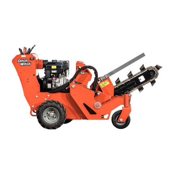
Intended Use Intended Use The C12, C14 and C16 pedestrian trenchers are designed to install buried cable and pipe. The maximum trenching depth is 30” (762 mm). The maximum trenching width is 6” (200 mm). These units are intended for operation in ambient temperatures from 20° to 115°F (-7° to 46°C). Use in any other way is considered contrary to the intended use. -
Page 5: Operator Orientation
C12/C14/C16 Operator’s Manual Overview - 5 Operator Orientation Operator Orientation 1. Front of unit 2. Right side of unit 3. Rear of unit 4. Left side of unit Operating Area The operating area (A) is at the rear of the machine, behind the control console. -
Page 6: About This Manual
C12/C14/C16 Operator’s Manual Overview - 6 About This Manual About This Manual This manual contains information for the proper use of this machine. See the beige Operation Overview pages for basic operating procedures. Cross references such as “See page 50” will direct you to detailed procedures. - Page 7 C12/C14/C16 Operator’s Manual Overview - 7 About This Manual...
-
Page 8: Foreword
If you need a replacement copy, contact your Ditch Witch dealer. If you need assistance in locating a dealer, visit our website at www.ditchwitch.com or write to the following address: The Charles Machine Works, Inc. Attn: Marketing Department PO Box 66 Perry, OK 73077-0066 The descriptions and specifications in this manual are subject to change without notice. - Page 9 Issue number 1.0/OM-03/16 Part number 053-2868 Copyright 2016 by The Charles Machine Works, Inc. , Ditch Witch, CMW and Roto Witch are registered trademarks of The Charles Machine Works, Inc. This product and its use may be covered by one or more patents at http://patents.charlesmachine.works.
- Page 10 C12/C14/C16 Operator’s Manual Contents - 10 Contents Overview machine serial number, information about the type of work this machine is designed to perform, basic machine components, and how to use this manual Foreword part number, revision level, and publication date of this manual, and factory contact...
- Page 11 C12/C14/C16 Operator’s Manual Contents - 11 Specifications machine specifications including weights, measurements, power ratings, and fluid capacities Support the warranty policy for this machine, and procedures for obtaining warranty consideration and training Service Record a record of major service performed on the machine...
-
Page 12: Safety
C12/C14/C16 Operator’s Manual Safety - 12 Safety Chapter Contents Guidelines ....... . 13 California Proposition 65 Warning . -
Page 13: Guidelines
C12/C14/C16 Operator’s Manual Safety - 13 Guidelines Guidelines Follow these guidelines before operating any jobsite equipment: • Complete proper training and read operator’s manual before using equipment. • Mark proposed path with white paint and have underground utilities located before working. In the US or Canada, call 811 (US) or 888-258-0808 (US and Canada). -
Page 14: Emergency Procedures
C12/C14/C16 Operator’s Manual Safety - 14 Emergency Procedures Emergency Procedures Jobsite hazards could cause death or serious injury. Use correct equipment and work methods. Use and maintain proper safety equipment. Before operating any equipment, review emergency procedures and check that all safety precautions have been taken. -
Page 15: If An Electric Line Is Damaged
C12/C14/C16 Operator’s Manual Safety - 15 Emergency Procedures If an Electric Line is Damaged If you suspect an electric line has been damaged and you are near pedestrian unit, DO NOT MOVE and do not touch unit. Take the following actions. The order and degree of action will depend upon the situation. -
Page 16: If A Gas Line Is Damaged
C12/C14/C16 Operator’s Manual Safety - 16 Emergency Procedures If a Gas Line is Damaged Fire or explosion possible. Fumes could ignite and cause burns. No smoking, no flame, no spark. Explosion possible. Serious injury or equipment damage could occur. Follow directions carefully. -
Page 17: If A Fiber Optic Cable Is Damaged
C12/C14/C16 Operator’s Manual Safety - 17 Emergency Procedures If a Fiber Optic Cable is Damaged Do not look into cut ends of fiber optic or unidentified cable. Vision damage can occur. Contact utility company. If Machine Catches on Fire Perform emergency shutdown procedure and then take the following actions. The order and degree of action will depend on the situation. -
Page 18: Safety Alert Classifications
C12/C14/C16 Operator’s Manual Safety - 18 Safety Alert Classifications Safety Alert Classifications These classifications and the icons defined on the following pages work together to alert you to situations which could be harmful to you, jobsite bystanders or your equipment. When you see these words and icons in the book or on the machine, carefully read and follow all instructions. - Page 19 C12/C14/C16 Operator’s Manual Safety - 19 Machine Safety Alerts Machine Safety Alerts Lift point. See Transport chapter for more information. 274-442 Fire or explosion possible. Fumes could ignite and cause burns. No smoking, no flame, no spark. 275-419 Tiedown location. See Transport chapter for more information.
- Page 20 Exposure to high noise levels may cause hearing loss. Wear hearing protection. 700-009 Moving digging teeth can kill. Trench cave-in can cause you to fall. Stay away. Tip over possible. When loading/unloading run at low idle and keep boom low. 270-6705 (C12/C14) / 270-6706 (C16)
- Page 21 C12/C14/C16 Operator’s Manual Safety - 21 Machine Safety Alerts...
-
Page 22: Operation Overview
C12/C14/C16 Operator’s Manual Operation Overview - 22 Operation Overview Chapter Contents Plan ........23 Trench . - Page 23 C12/C14/C16 Operator’s Manual Operation Overview - 23 Plan Plan 1. Gather information about jobsite. See page 35. 2. Inspect jobsite. See page 36. 3. Classify jobsite. See page 37. 4. Select best chain type and tooth pattern for your application. See page 61.
-
Page 24: Controls
Trail Wheel Pin ......27 C12 Engine Controls......28 C14 Engine Controls. - Page 25 C12/C14/C16 Operator’s Manual Controls - 25 Control Console Control Console 1. Boom lift control (green) 4. Hourmeter/tachometer 2. Speed/direction controls 5. Parking brake lever 3. Digging chain control Item Description Notes 1. Boom lift control To lower boom, push. (green)
- Page 26 C12/C14/C16 Operator’s Manual Controls - 26 Control Console Item Description Notes 2. Speed/direction To drive straight forward, Trenching movement is always controls push BOTH controls slowly backward (toward you). forward. To drive straight in reverse, pull BOTH controls slowly rearward.
- Page 27 C12/C14/C16 Operator’s Manual Controls - 27 Trail Wheel Pin Item Description Notes 5. Parking brake IMPORTANT: To engage parking brake, • Move unit slightly to ensure move lever to the right. parking brake is engaged. • If necessary, move unit slightly to To disengage parking brake, disengage parking brake.
- Page 28 C12/C14/C16 Operator’s Manual Controls - 28 C12 Engine Controls C12 Engine Controls 1. Fuel shut-off valve 4. Starter grip 2. Choke control 5. Ignition switch 3. Throttle control Item Description Notes 1. Fuel shut-off valve To close fuel shut-off valve, Close valve: move lever to the left position.
- Page 29 C12/C14/C16 Operator’s Manual Controls - 29 C12 Engine Controls Item Description Notes 2. Choke control To close choke control, move Close choke control to start a cold lever to the left. engine. To open choke control, move Wait for a few seconds, then gradually lever to the right.
- Page 30 C12/C14/C16 Operator’s Manual Controls - 30 C14 Engine Controls C14 Engine Controls 1. Fuel shut-off valve 4. Starter grip 2. Choke control 5. Ignition switch 3. Throttle control Item Description Notes 1. Fuel shut-off valve To close fuel shut-off valve, Close valve: move lever to the left position.
- Page 31 C12/C14/C16 Operator’s Manual Controls - 31 C14 Engine Controls Item Description Notes 2. Choke control To close choke control, move Close choke control to start a cold lever to the left. engine. To open choke control, move Wait for a few seconds, then gradually lever to the right.
- Page 32 C12/C14/C16 Operator’s Manual Controls - 32 C16 Engine Controls C16 Engine Controls 1. Throttle control 3. Ignition switch 2. Choke control 4. Fuel shut-off valve Item Description Notes 1. Throttle control To increase engine speed, pull up. To decrease engine speed, push down.
- Page 33 C12/C14/C16 Operator’s Manual Controls - 33 C16 Engine Controls Item Description Notes 3. Ignition switch To start engine, turn key all the way clockwise. Release key as engine starts. To stop engine, turn key counterclockwise. 4. Fuel shut-off valve To close fuel shut-off valve, Close valve: move lever clockwise.
-
Page 34: Prepare
C12/C14/C16 Operator’s Manual Prepare - 34 Prepare Chapter Contents Gather Information ......35 • Review Job Plan ......... . .35 •... -
Page 35: Gather Information
C12/C14/C16 Operator’s Manual Prepare - 35 Gather Information Gather Information A successful job begins before you dig. The first step in planning is reviewing information already available about the job and jobsite. Review Job Plan Review blueprints or other plans. Check for information about existing or planned structures, elevations, or proposed work that may be taking place at the same time. -
Page 36: Inspect Site
C12/C14/C16 Operator’s Manual Prepare - 36 Inspect Site Inspect Site Identify Hazards Inspect jobsite before transporting equipment. Check for the following: • overall grade or slope • changes in elevation such as hills or open trenches • obstacles such as buildings, railroad crossings, or streams •... -
Page 37: Classify Jobsite
C12/C14/C16 Operator’s Manual Prepare - 37 Classify Jobsite Classify Jobsite Jobsite hazards could cause death or serious injury. Use correct equipment and work methods. Use and maintain proper safety equipment. 274-050; 274-724 (2P) To help avoid injury: • Wear personal protective equipment including hard hat, safety eye wear, and hearing protection. -
Page 38: Apply Precautions
C12/C14/C16 Operator’s Manual Prepare - 38 Classify Jobsite Apply Precautions Once classified, precautions appropriate for jobsite must be taken. Follow U.S. Department of Labor regulations on excavating and trenching (Part 1926, Subpart P) and other similar regulations. Electric Jobsite Precautions Electric shock will cause death or serious injury. - Page 39 C12/C14/C16 Operator’s Manual Prepare - 39 Classify Jobsite Crystalline Silica (Quartz) Dust Precautions Cutting, drilling, or working materials such as concrete, sand, or rock containing quartz may result in exposure to silica dust. Breathing crystalline silica dust may cause lung disease. Use dust control methods or appropriate breathing protection when exposed to silica dust.
-
Page 40: Check Supplies And Prepare Equipment
C12/C14/C16 Operator’s Manual Prepare - 40 Check Supplies and Prepare Equipment Check Supplies and Prepare Equipment Check Supplies • fuel • keys • personal protective equipment, such as hard hat and safety glasses Prepare Equipment Check Levels • fuel •... - Page 41 C12/C14/C16 Operator’s Manual Prepare - 41 Check Supplies and Prepare Equipment...
-
Page 42: Drive
C12/C14/C16 Operator’s Manual Drive - 42 Drive Chapter Contents Start ........43 •... -
Page 43: Start
C12/C14/C16 Operator’s Manual Drive - 43 Start Start Start Unit Fire or explosion possible. To help avoid injury: Do not use starter fluid. C12 and C14 1. Ensure all controls are in neutral. 2. Move fuel shut-off valve to ON position. -
Page 44: Warm Up Unit
C12/C14/C16 Operator’s Manual Drive - 44 Drive Warm up Unit Incorrect control function can cause death or serious injury. To help avoid injury: If controls do not operate as given in instructions: • Shut down machine immediately. • Have machine repaired. -
Page 45: Drive On A Slope
C12/C14/C16 Operator’s Manual Drive - 45 Drive on a Slope Drive on a Slope Machine can tip over and crush you. To help avoid injury: • Operate from uphill side of machine. • Keep digging boom low. • Drive cautiously at all times. -
Page 46: Shut Down
C12/C14/C16 Operator’s Manual Drive - 46 Shut Down Shut Down 1. Release speed/direction controls. 2. If space is sufficient, push boom control to lower digging boom. 3. Run engine at low throttle for three minutes. 4. Turn ignition switch to OFF position. - Page 47 C12/C14/C16 Operator’s Manual Drive - 47 Shut Down...
-
Page 48: Transport
C12/C14/C16 Operator’s Manual Transport - 48 Transport Chapter Contents Lift ........49 •... -
Page 49: Lift
C12/C14/C16 Operator’s Manual Transport - 49 Lift Lift Crushing weight could cause death or serious injury. Stay away. To help avoid injury: • Use applicable lifting device and lifting equipment. • Only use approved lifting points. • Stay away from lifted load. -
Page 50: Haul
C12/C14/C16 Operator’s Manual Transport - 50 Haul Haul Load ® IMPORTANT: Ditch Witch S2B trailer is recommended for transport. If you use a different trailer, obey additional instructions from the manufacturer. Prepare trailer 1. Attach trailer to vehicle. 2. Park vehicle with trailer on level and firm ground. -
Page 51: Tie Down
C12/C14/C16 Operator’s Manual Transport - 51 Haul Tie Down Crushing weight could cause death or serious injury. Stay away. To help avoid injury: • Only use approved tiedown points. • Use applicable tiedown equipment. Tiedown points Tiedown points are identified by tiedown decals. - Page 52 C12/C14/C16 Operator’s Manual Transport - 52 Haul 1. Install trail wheel between front tiedown plates and engage pin (1). 2. Secure pin (1) with clip pin (2). 3. Install latch plate (3) at bottom rear of machine. 4. Attach latch plate (3) to link (6) with pin (4).
-
Page 53: Unload
C12/C14/C16 Operator’s Manual Transport - 53 Retrieve Unload ® IMPORTANT: Use Ditch Witch S2B trailer for transport. If you use a different trailer, obey additional instructions from the manufacturer. Prepare trailer 1. Park vehicle with trailer on level and firm ground. -
Page 54: Trench
C12/C14/C16 Operator’s Manual Trench - 54 Trench Chapter Contents Precautions ....... 55 Set Up. -
Page 55: Precautions
C12/C14/C16 Operator’s Manual Trench - 55 Precautions Precautions Electric shock will cause death or serious injury. To help avoid injury: • Know location of electrical lines and stay away. • Carefully expose lines by hand before digging. Read operator’s manual. Know how to use all controls. -
Page 56: Set Up
C12/C14/C16 Operator’s Manual Trench - 56 Set Up Set Up 1. Ensure all preparatory tasks have been done correctly. See “Prepare” on page 34. 2. Ensure engine is shut down. 3. Ensure restraint bar is installed correctly: • Danger word must be facing up, as shown. -
Page 57: Operate
C12/C14/C16 Operator’s Manual Trench - 57 Operate Operate Dig Trench Moving digging teeth can kill. Trench cave-in can cause 6ft/2m you to fall. Stay away. To help avoid injury: • Keep everyone at least 6’ (2 m) from machine, digging boom, and their range of movement. -
Page 58: Remove Objects From Digging Chain
C12/C14/C16 Operator’s Manual Trench - 58 Finish Job Remove Objects from Digging Chain If object becomes lodged in chain: 1. Release speed/direction controls. 2. Move digging chain control to neutral position. 3. Slightly pull boom lift control to raise boom just out of ground. - Page 59 C12/C14/C16 Operator’s Manual Trench - 59 Finish Job...
-
Page 60: Systems And Equipment
C12/C14/C16 Operator’s Manual Systems and Equipment - 60 Systems and Equipment Chapter Contents Chain, Teeth, and Sprockets ....61 • Chain and Tooth Maintenance ....... .61 •... -
Page 61: Chain, Teeth, And Sprockets
C12/C14/C16 Operator’s Manual Systems and Equipment - 61 Chain, Teeth, and Sprockets Chain, Teeth, and Sprockets Chain and Tooth Maintenance • Always replace sprockets at the same time you replace the digging chain. Sprockets and chain are designed to work together. Replacing one without the other will cause premature wear of the new part. -
Page 62: Chain Selection
C12/C14/C16 Operator’s Manual Systems and Equipment - 62 Chain, Teeth, and Sprockets Chain Selection These charts are meant as a guideline only. No one chain type works well in all conditions. See your ® Ditch Witch dealer for soil conditions and chain recommendations for your area. Ask for the latest Chain, Teeth, and Sprockets Parts Catalog. -
Page 63: Optional Equipment
C12/C14/C16 Operator’s Manual Systems and Equipment - 63 Optional Equipment Optional Equipment ® See your Ditch Witch dealer for more information about the following optional equipment. NOTICE: Adding or removing optional equipment changes counterweight requirement. Use applicable chart on page 65 to ensure you have the correct counterweights for your configuration. -
Page 64: Backfill Blade
C12/C14/C16 Operator’s Manual Systems and Equipment - 64 Optional Equipment Backfill Blade The optional backfill blade must be in position related to the job at hand. Stowed position Install the backfill blade in stowed position for transport and drilling. 1. Shut down engine. -
Page 65: Counterweights
C12/C14/C16 Operator’s Manual Systems and Equipment - 65 Optional Equipment Counterweights Select the applicable counterweight configuration to balance the machine. IMPORTANT: Do not add more counterweights than indicated. 1. Use the chart that follow to determine the correct number of counterweights. -
Page 66: Complete The Job
C12/C14/C16 Operator’s Manual Complete the Job - 66 Complete the Job Chapter Contents Restore Jobsite ......67 Rinse Equipment . - Page 67 C12/C14/C16 Operator’s Manual Complete the Job - 67 Restore Jobsite Restore Jobsite After product is installed, return spoils to the trench with optional backfill blade, shovels, or small earth- moving equipment. See “Backfill Blade” on page 64. Rinse Equipment Spray water onto equipment to remove dirt and mud.
-
Page 68: Service
C12/C14/C16 Operator’s Manual Service - 68 Service Chapter Contents Precautions ....... 69 Recommended Lubricants/Service Key . -
Page 69: Precautions
C12/C14/C16 Operator’s Manual Service - 69 Precautions Precautions Read operator's manual. Know how to use all controls. Your safety is at stake. To help avoid injury: • Unless otherwise instructed, do all service tasks with engine off. • Refer to engine manufacturer’s manual for engine maintenance instructions. -
Page 70: Recommended Lubricants/Service Key
C12/C14/C16 Operator’s Manual Service - 70 Recommended Lubricants/Service Key Recommended Lubricants/Service Key Item Description Diesel engine oil meeting API service classification CF-4 or E1-96 and SAE viscosity recommended by engine manufacturer (SAE15W40) Gasoline engine oil meeting or exceeding API SJ. See oil temperature chart for recommended viscosity grade for each model. -
Page 71: Oil Temperature Chart
C12/C14/C16 Operator’s Manual Service - 71 Engine Oil Temperature Chart Engine Oil Temperature Chart ® C12 Honda GX390 Temperature range anticipated before next oil change ® C14 and C16 Briggs & Stratton Temperature range anticipated before next oil change *Below 40°F (4°C) the use of SAE 30 will result in hard starting. -
Page 72: Each Use
C12/C14/C16 Operator’s Manual Service - 72 Each Use Each Use Location Task Notes Engine Clean exterior surfaces with wet cloth Check fuel level and refuel Check starter rope and starter grip C12, C14 Check engine oil level Check air filter elements... - Page 73 C12/C14/C16 Operator’s Manual Service - 73 Each Use Check Starter Rope and Starter Grip ® C12: Honda GX390 Check starter rope and starter grip for condition before each use. If worn or damaged: • Do not start unit. ® •...
- Page 74 C12/C14/C16 Operator’s Manual Service - 74 Each Use Check Engine Oil Level ® C12: Honda GX390 Check engine oil before each use. 1. Check engine oil at dipstick. 2. If low, add GEO at oil fill until oil level is at FULL mark on dipstick.
- Page 75 C12/C14/C16 Operator’s Manual Service - 75 Each Use Check Air Filter Elements Check air filter elements before each use. 1. Remove wing nut (1) and air filter cover (2). 2. Remove wing nut (3) and air filter elements (4) and (5).
- Page 76 C12/C14/C16 Operator’s Manual Service - 76 Each Use Check Hydraulic Fluid Level Check hydraulic fluid level before each use. Contents under pressure. Relieve pressure before opening. Death or injury could occur. To help avoid injury: • Wear gloves and safety glasses.
- Page 77 C12/C14/C16 Operator’s Manual Service - 77 Each Use Check Hydraulic Hoses Check hydraulic hoses for leaks and hydraulic connections for tightness before each use and every 10 hours. Replace any damaged part. Fluid under pressure can pierce skin and cause death or serious injury.
- Page 78 C12/C14/C16 Operator’s Manual Service - 78 Each Use Check Lug Nut Torque Check lug nut torque before each use. Tighten to 65 ft•lb (88 N•m). Check Parking Brake Check parking brake operation before each use. 1. To engage parking brake, move lever to the right.
-
Page 79: Hour
C12/C14/C16 Operator’s Manual Service - 79 5 Hour Service 5 Hour Service Location Task Notes Engine Change engine oil Initial, C14, C16, GEO Change Engine Oil ® C14: Briggs & Stratton XR2100 Change engine oil after the first 5 hours of operation and every 100 hours thereafter. -
Page 80: Hour
C12/C14/C16 Operator’s Manual Service - 80 10 Hour Service 10 Hour Service Location Task Notes Trencher Check digging chain Check digging chain tension Check restraint bar position Check trench cleaner position Check Digging Chain Check digging chain for wear every 10 hours. - Page 81 C12/C14/C16 Operator’s Manual Service - 81 10 Hour Service Check Digging Chain Tension Check digging chain tension every 10 hours and adjust as needed. NOTICE: Overtightening will cause chain stretch, loss of machine performance, and possible premature chain failure. •...
- Page 82 C12/C14/C16 Operator’s Manual Service - 82 10 Hour Service Check Trench Cleaner Position Check trench cleaner position every 10 hours and after each adjustment or replacement of the digging chain. The trench cleaner is correctly positioned when there is 3-4 in (76-102 mm) between the digging teeth and the inside of the trench cleaner shoe (A).
-
Page 83: Hour
C12/C14/C16 Operator’s Manual Service - 83 20 Hour Service 20 Hour Service Location Task Notes Engine Change engine oil Initial, C12, GEO Change Engine Oil ® C12: Honda GX390 Change engine oil and filter after the first 20 hours of operation and every 100 hours thereafter. -
Page 84: Hour
C12/C14/C16 Operator’s Manual Service - 84 50 Hour Service 50 Hour Service Location Task Notes Engine Change engine oil and filter C16, GEO Check muffler and spark arrester C14, C16 Trencher Check boom mounting bolts 220 ft•lb (300 N•m) Change Engine Oil and Filter ®... - Page 85 C12/C14/C16 Operator’s Manual Service - 85 50 Hour Service Check Boom Mounting Bolts Check boom mounting bolts every 10 hours. 1. Check bolts for wear. Replace if worn or damaged. 2. Check torque and ensure bolts are tightened to 220 ft•lb (300 N•m).
-
Page 86: Hour
C12/C14/C16 Operator’s Manual Service - 86 100 Hour Service 100 Hour Service Location Task Notes Engine Change engine oil and filter C12, C14, GEO Change air filter elements Check spark plug Clean sediment cup Clean fuel tank and filter Change Engine Oil and Filter ®... - Page 87 C12/C14/C16 Operator’s Manual Service - 87 100 Hour Service Change Air Filter Elements Change air filter elements every 100 hours. 1. Remove wing nut (1), air filter cover (2) and wing nut (3). 2. Remove and replace air filter elements (4) and (5).
- Page 88 C12/C14/C16 Operator’s Manual Service - 88 100 Hour Service Change air filter element every 100 hours. 1. Remove wing nuts (1) and cover (2). 2. Remove and replace air filter element (3). NOTICE: Cleaning can damage filter element. • Do not tap filter element to loosen dirt.
-
Page 89: Hour
C12/C14/C16 Operator’s Manual Service - 89 250 Hour Service 250 Hour Service Location Task Notes Engine Check idle speed Trencher Adjust valve train Check Idle Speed ® Contact your local Honda dealer to check and adjust the idle speed every 250 hours. -
Page 90: Hour
C12/C14/C16 Operator’s Manual Service - 90 500 Hour Service 500 Hour Service Location Task Notes Trencher Change hydraulic fluid and filter Change Hydraulic Fluid and Filter Change hydraulic fluid and filter every 500 hours. 1. Place an appropriate container below hydraulic drain (3). -
Page 91: As Needed
C12/C14/C16 Operator’s Manual Service - 91 As Needed As Needed Location Task Notes Trencher Check battery Replace digging chain Check Battery Check battery as needed. Keep battery clean and terminals free of corrosion. Explosion possible. Serious injury or equipment damage could occur. - Page 92 C12/C14/C16 Operator’s Manual Service - 92 As Needed Jump Start Battery Explosion possible. Serious injury or equipment damage could occur. To help avoid injury: • Wear the necessary personal protective equipment, including sufficiently insulated gloves and safety glasses. • Keep sparks, fire and other ignition sources away.
- Page 93 C12/C14/C16 Operator’s Manual Service - 93 As Needed Set up and Check Acid in battery is corrosive. Contact with skin will cause burns. To help avoid injury: • Avoid contact with battery fluid. • Wear applicable safety glasses and gloves.
- Page 94 C12/C14/C16 Operator’s Manual Service - 94 As Needed Connect Batteries 1. Connect red positive (+) cable clamp to positive (+) post (2) of disabled battery. IMPORTANT: Some machines have an external positive terminal (1). In that case, connect positive clamp to external terminal.
- Page 95 C12/C14/C16 Operator’s Manual Service - 95 As Needed Remove Chain 1. Start engine. See “Start Unit” on page 43. 2. Operate digging chain control until digging chain connector pin is on top of boom. 3. Operate boom lift control to lower boom to ground.
- Page 96 C12/C14/C16 Operator’s Manual Service - 96 As Needed Install Chain 1. Lay chain on ground with teeth down and pointed toward unit. Loop cable through end links. 2. Start engine. See “Start Unit” on page 43. 3. Disengage parking brake.
- Page 97 C12/C14/C16 Operator’s Manual Service - 97 As Needed...
- Page 98 C12 ........99...
- Page 99 C12/C14/C16 Operator’s Manual Specifications - 99 Dimensions U.S. Metric Trench depth, maximum 24 in 610 mm Trench width 3.5 - 6 in 90-152 mm Boom travel down 60° 60° Boom travel up 29° 29° Headshaft height, digging chain 13.2 in...
- Page 100 C12/C14/C16 Operator’s Manual Specifications - 100 Operational U.S. Metric Vehicle speeds Maximum transit forward 280 fpm 85.3 m/min Maximum transit reverse 114 fpm 34.7 m/min Digging chain speed 416 fpm 126.8 m/min 351 fpm 107 m/min Spoils handling (single, open-end auger):...
- Page 101 C12/C14/C16 Operator’s Manual Specifications - 101 Power Train U.S. Metric Hydraulic ground drive: infinitely variable from zero to maximum, speed and direction controlled with dual levers Digging chain drive: hydraulic direct drive, lever-operated, one speed forward and reverse Trencher drive: hydraulic direct drive...
- Page 102 C12/C14/C16 Operator’s Manual Specifications - 102 Dimensions U.S. Metric Trench depth, maximum 24 in 610 mm Trench width 3.5 - 6 in 90-152 mm Boom travel down 60° 60° Boom travel up 29° 29° Headshaft height, digging chain 13.2 in...
- Page 103 C12/C14/C16 Operator’s Manual Specifications - 103 Operational U.S. Metric Vehicle speeds Maximum transit forward 280 fpm 85.3 m/min Maximum transit reverse 114 fpm 34.7 m/min Digging chain speed 416 fpm 126.8 m/min 351 fpm 107 m/min Spoils handling (single, open-end auger):...
- Page 104 C12/C14/C16 Operator’s Manual Specifications - 104 Power Train U.S. Metric Hydraulic ground drive: infinitely variable from zero to maximum, speed and direction controlled with dual levers Digging chain drive: hydraulic direct drive, lever-operated, one speed forward and reverse Trencher drive: hydraulic direct drive...
- Page 105 C12/C14/C16 Operator’s Manual Specifications - 105 Dimensions U.S. Metric Trench depth, maximum 30 in 762 mm Trench width 3.5 - 6 in 89-150 mm Boom travel down 60° 60° Boom travel up 60° 60° Headshaft height, digging chain 13.2 in...
- Page 106 C12/C14/C16 Operator’s Manual Specifications - 106 Operational U.S. Metric Vehicle speeds Maximum transit forward 280 fpm 85.3 m/min Maximum transit reverse 125 fpm 38.1 m/min Digging chain speed 366 fpm 111.6 m/min 309 fpm 94.2 m/min Spoils handling (single, open-end auger):...
- Page 107 C12/C14/C16 Operator’s Manual Specifications - 107 Power Train U.S. Metric Hydraulic ground drive: infinitely variable from zero to maximum, speed and direction controlled with dual levers Digging chain drive: hydraulic direct drive, lever-operated, one speed forward and reverse Trencher drive: hydraulic direct drive...
- Page 108 C12/C14/C16 Operator’s Manual Support - 108 Procedure Support Procedure ® Notify your dealer immediately of any malfunction or failure of Ditch Witch equipment. Always give model, serial number, and approximate date of your equipment purchase. This information should be recorded and placed on file by the owner at the time of purchase.
- Page 109 Subject to the limitation and exclusions herein, free replacement parts will be provided at any authorized Ditch Witch dealership for any Ditch Witch equipment or parts manufactured by The Charles Machine Works, Inc. (CMW) that fail due to a defect in material or workmanship within one (1) year of first commercial use.
- Page 112 C12/C14/C16 Operator’s Manual Service Record - 112 Service Record Service Performed Date Hours...
- Page 113 C12/C14/C16 Operator’s Manual Service Record - 113 Service Performed Date Hours...
Need help?
Do you have a question about the C12 and is the answer not in the manual?
Questions and answers