
Summary of Contents for WATERS CORPORATION TA Instruments DSC 2010
- Page 1 DSC 2010 Differential Scanning Calorimeter Operator’s Manual PN 925604.001 Rev. E (Text and Binder) PN 925604.002 Rev. E (Text Only) Issued May 1998 TA I DSC 2010 NSTRUMENTS...
- Page 2 ©1995, 1996, 1997, 1998 by TA Instruments 109 Lukens Drive New Castle, DE 19720 Notice The material contained in this manual is be- lieved adequate for the intended use of this instrument. If the instrument or procedures are used for purposes other than those specified herein, confirmation of their suitability must be obtained from TA Instruments.
-
Page 3: Table Of Contents
Table of Contents Notes, Cautions, and Warnings ....ix Safety ............. x Using This Manual ........xv CHAPTER 1: Introducing the DSC 2010 ..........1-1 Introduction..........1-3 Components ..........1-5 The 2010 Instrument ........1-6 2010 Instrument Keypad ......1-7 POWER Switch ........ 1-9 2010 DSC Cell ......... - Page 4 Table of Contents (continued) CHAPTER 2: Installing the DSC 2010 ........... 2-1 Unpacking/Repacking the 2010 ....2-3 Unpacking the 2010 ........ 2-3 Unpacking the DSC Cell ......2-6 Repacking the 2010 ......... 2-6 Installing the 2010 Instrument ....2-7 Inspecting the System......2-7 Choosing a Location .......
- Page 5 Table of Contents (continued) CHAPTER 3: Running Experiments ..3-1 Overview ............. 3-3 Before You Begin ........3-3 Calibrating the DSC ........3-4 Baseline Slope and Offset Calibration ..3-5 Cell Constant Calibration ......3-6 Temperature Calibration ......3-6 Running a DSC Experiment ....... 3-7 Experimental Procedure ......
- Page 6 Table of Contents (continued) Starting an Experiment ......3-23 Stopping an Experiment ......3-23 Subambient Experiments ......3-24 DSC Cooling Can ........3-24 Applications ........3-24 Operation ..........3-25 Quench-Cooling Between Runs ......... 3-25 Starting a Run Below Ambient Temperature ..... 3-26 Programmed Cooling ......
- Page 7 Table of Contents (continued) Guidelines for Quantitative Studies ..4-12 Specific Heat Experiments ....4-12 CHAPTER 5: Maintenance and Diagnostics ......... 5-1 Overview ............. 5-3 Routine Maintenance ........5-4 Inspection ..........5-4 Cleaning the Instrument Keypad ..... 5-4 Cleaning a Contaminated Cell ....5-4 Cleaning DSC Pans .........
- Page 8 Table of Contents (continued) Appendix A: Sample Encapsulating Press......... A-1 Appendix B: Ordering Information ..........B-1 Index............I-1 viii TA I DSC 2010 NSTRUMENTS...
-
Page 9: Notes, Cautions, And Warnings
Notes, Cautions, and Warnings This manual uses NOTES, CAUTIONS, and WARNINGS to emphasize important and critical instructions. NOTE: A NOTE highlights important information about equipment or procedures. A CAUTION emphasizes a procedure that may CAUTION: damage equipment or cause loss of data if not followed correctly. -
Page 10: Safety
Safety This equipment has been designed to comply with the following standards on safety: • IEC 1010-1/1990 and A1/1992 • IEC 1010-2-010/1992 • EN 61010-1/1992 • EN 61010-2-010/1994 • UL 3101-1, First Edition. Electrical Safety You must unplug the instrument before doing any maintenance or repair work;... - Page 11 WARNING Potential Asphyxiant Liquid nitrogen can cause rapid suffocation without warning. Store and use in an area with adequate ventilation. Do not vent LNCA container in confined spaces. Do not enter confined spaces where nitrogen gas may be present unless the area is well ventilated. The warning above applies to the use of liquid nitrogen.
- Page 12 Safety (continued) Handling Liquid Nitrogen The DSC 2010 uses the cryogenic (low-tempera- ture) agent, liquid nitrogen, for cooling. Be- cause of its low temperature (-195°C), liquid nitrogen will burn the skin. When you work with liquid nitrogen, use the following precau- tions: Liquid nitrogen evaporates rapidly at room WARNING...
- Page 13 Safety (continued) IF A PERSON IS BURNED BY LIQUID NITROGEN . . . 1. IMMEDIATELY flood the area (skin or eyes) with large quantities of cool water, and then apply cold compresses. 2. If the skin is blistered or if there is a chance of eye infection, take the person to a doctor IMMEDIATELY.
- Page 14 Safety (continued) Lifting the Instrument The DSC 2010 is a fairly heavy instrument. In order to avoid injury, particularly to the back, please follow this advice: Use two people to lift and/or carry the WARNING instrument. The instrument is too heavy for one person to handle safely.
-
Page 15: Using This Manual
Using This Manual Chapter 1 Describes the 2010 instrument and its specifications. Chapter 2 Describes how to connect the 2010 instrument to the rest of your system. Chapter 3 Describes how to run DSC experiments. Chapter 4 Provides technical information and explains the DSC principles of operation. - Page 16 TA I DSC 2010 NSTRUMENTS...
- Page 17 CHAPTER 1: Introducing the DSC 2010 Introduction..........1-3 Components ..........1-5 The 2010 Instrument ........1-6 2010 Instrument Keypad ......1-7 POWER Switch ........ 1-9 2010 DSC Cell ......... 1-9 Accessories ..........1-10 Sample Encapsulating Press ....1-10 Accessories for Subambient Operation ......
- Page 18 Introducing the DSC 2010 1–2 TA I DSC 2010 NSTRUMENTS...
-
Page 19: Introduction
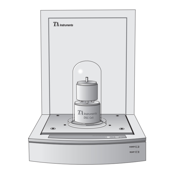
Introduction Introduction The Differential Scanning Calorimeter (DSC) 2010 (Figure 1.1) determines the temperature and heat flow associated with material transi- tions as a function of time and temperature. It also provides quantitative and qualitative data on endothermic (heat absorption) and exother- mic (heat evolution) processes of materials during physical transitions that are caused by phase changes, melting, oxidation, and other... - Page 20 Introducing the DSC 2010 Figure 1.1 DSC 2010 with TA Instruments Thermal Analyzer 1–4 TA I DSC 2010 NSTRUMENTS...
-
Page 21: The Dsc 2010
Introduction Components The DSC 2010 (see Figure 1.2) has two major parts: the 2010 instrument, which contains the system electronics, and the cell, which contains its own thermocouples (temperature sensors) for monitoring differential heat flow and tempera- tures. The 2010 DSC cell is not interchangeable with other cells or cell types. -
Page 22: The 2010 Instrument
Introducing the DSC 2010 The 2010 Instrument The 2010 instrument contains the electronics and software needed to perform experiments and store experimental results. The battery backed- up RAM in the instrument saves parameters vital to system operations if power is inter- rupted. -
Page 23: 2010 Instrument Keypad
The 2010 Instrument 2010 Instrument Keypad The instrument keypad (see Figure 1.3) contains keys that control local operations at the instru- ment. Experiment information and instrument constants NOTE: are entered from the controller keyboard, not the instrument keypad. Table 1.1 explains the functions of the instru- ment keys. - Page 24 Introducing the DSC 2010 Table 1.1 2010 Instrument Keypad Function Keys Key/Function Explanation START Initiates the experiment after checking the method and the cell. This is the same function as Start on the controller. STOP If an experiment is running, this key ends the method normally, as though it had run to com- pletion;...
-
Page 25: Power Switch
The 2010 Instrument POWER Switch The POWER switch on the back of the instru- ment turns the power to 2010 instrument on and off. The green power light on the front panel shows that the instrument is ON. The yellow light shows when the instrument is ready. -
Page 26: Accessories
Introducing the DSC 2010 Accessories Sample Encapsulating Press The TA Instruments Sample Encapsulating Press (Figure 1.5) is used to prepare encapsu- lated samples for DSC experiments. It comes with two sets of dies, one for hermetic and one for nonhermetic sealing. Figure 1.5 Sample Encapsulating Press 1–10... -
Page 27: Accessories For Subambient Operation
Accessories Accessories for Subambient Operation The DSC 2010 can be operated at below- ambient temperatures using one of three acces- sories: the Liquid Nitrogen Cooling Accessory (LNCA), the Refrigerated Cooling System (RCS), or the DSC Cooling Can. LNCA The LNCA (Figure 1.6) achieves automatic and continuous programmed sample cooling within the range of -150°C to 725°C when used with the DSC Heat Exchanger installed on the DSC... -
Page 28: Rcs
Introducing the DSC 2010 Refrigerated Cooling System (RCS) The Refrigerated Cooling System (RCS), which is used to cool DSC experiments, consists of a two-stage, cascade, vapor compression refrigera- tion system with an attached cooling head. The cooling head fits over the RCS-DSC cell for use with the DSC 2010. -
Page 29: Dsc Cooling Can
Accessories DSC Cooling Can The DSC Cooling Can fits over the standard DSC Cell and has a reservoir into which you can place coolant to cool the cell. Either quench cooling or manual programmed cooling can be performed. The manual programmed cooling requires operator maintenance of the coolant level in the reservoir. -
Page 30: Specifications
Introducing the DSC 2010 Specifications Tables 1.2 through 1.3 contain the technical specifications for the 2010 instrument. Table 1.2 2010Instrument Specifications Dimensions Depth 65.5 cm (25.8 in.) Width 28.5 cm (11.3in.) Height 40.0 cm (15.7 in.) Weight 20 kg (44 lb) (approx.) Power 115 volts AC +10%... - Page 31 Specifications Table 1.3 (continued) Sample volume 10 mm in hermetic pans Sample pans Various open or hermetically sealed Atmosphere Atmospheric to 266 Pa (2 torr); preheated dynamic gas purge (in excess of 100 mL/min) Purge Gases Recommended: air, argon, helium, nitrogen, or oxygen Typical flow rate 25-50 mL/min...
- Page 32 Introducing the DSC 2010 Table 1.3 (continued) Constant +2.5% from -100 to calorimetric sensitivity Calorimetric 1% (based on precision metal samples) Baseline noise 0.5 µW (rms) 1–16 TA I DSC 2010 NSTRUMENTS...
- Page 33 CHAPTER 2: Installation Unpacking/Repacking the 2010 ....2-3 Unpacking the 2010 ........ 2-3 Unpacking the DSC Cell ......2-6 Repacking the 2010 ......... 2-6 Installing the 2010 Instrument ....2-7 Inspecting the System ......2-7 Choosing a Location ....... 2-8 Connecting Cables and Gas Lines ..
- Page 34 Installation 2–2 TA I DSC 2010 NSTRUMENTS...
-
Page 35: Unpacking/Repacking The 2010
Unpacking/Repacking the 2010 Unpacking/Repacking the 2010 NOTE: These instructions are also found as separate unpacking instructions in the shipping box. Refer to Figures 1 to 3 while unpacking your instrument. Unpacking the 2010 Have an assistant help you unpack this WARNING unit. - Page 36 Installation 2. Remove the cardboard packing insert. 3. Stand at one end of the box with your assistant facing you at the other end. Lift your end of the unit out of the box as your assistant lifts his/her end. 4.
- Page 37 Unpacking/Repacking the 2010 5. While your assistant holds the unit, use a wrench to remove the two nuts and washers from the bottom. Then lift and rotate the unit so that the other end hangs over the edge of the bench. Someone must hold onto the unit at all times while it is in this position.
-
Page 38: Unpacking The Dsc Cell
Installation Unpacking the DSC Cell To unpack the DSC Cell on the 2010 instrument, follow the instructions below. 1. Remove the hold-down screws from the DSC bell jar shipping clamp. Remove the clamp. Install plugs (supplied in the acces- sory kit) into the holes. Remove the bell jar from the cell. -
Page 39: Installing The 2010 Instrument
Installing the Instrument Installing the Instrument Before shipment, the 2010 instrument is inspect- ed both electrically and mechanically so that it is ready for operation after it has been installed. Installation involves the following procedures, described in this chapter: • Unpacking the 2010 instrument and its components and accessory kit •... -
Page 40: Choosing A Location
Installing the DSC 2010 Choosing a Location Because of the sensitivity of DSC experiments, it is important to choose a proper location for the instrument. The 2010 instrument should be: . . . a temperature-controlled area..a clean environment. . -
Page 41: Connecting Cables And Gas Lines
Installing the Instrument Connecting Cables and Gas Lines To connect the cables and gas lines, you will need access to the 2010 instrument’s rear panel. All directional descriptions are written on the assumption that you are facing the back of the instrument. - Page 42 Installing the DSC 2010 5. Select a unique address from 1 to 9 (one that is not used by any other instruments or Instrument Interfaces connected to your controller). Then use the binary address switches on the 2010 instrument connector panel to set the desired address (see Table 2.1).
- Page 43 Installing the Instrument Table 2.1 Binary Address Settings* Address Switch Pattern 1 2 3 4 5 0 0 0 0 1 0 0 0 1 0 0 0 0 1 1 0 0 1 0 0 0 0 1 0 1 0 0 1 1 0 0 0 1 1 1 0 1 0 0 0...
-
Page 44: Purge, Vacuum, And Cooling Gas Lines
Installing the DSC 2010 Purge, Vacuum, and Cooling Gas Lines PURGE Line The PURGE gas is typically used to control the environment around the sample. 1. Locate the PURGE fitting on the right side of the 2010 instrument back (see Figure 2.6). -
Page 45: Vacuum Line
Installing the Instrument VACUUM Line The vacuum line will be needed if you are going to perform subambient experiments. Connect the line as follows: 1. Locate the VACUUM fitting on the right side of the 2010 instrument back (see Figure 2.6). - Page 46 Installing the DSC 2010 2. Make sure your cooling gas source is regulated between 20 and 120 psi. The COOLING GAS line ties into a pressure- NOTE: regulated valve that is set to 15 psi. The source pressure setting should not go below this value. 3.
-
Page 47: Power Cable
Installing the Instrument Power Cable Connect all other cables and gas lines before NOTE: connecting the power cable to a wall outlet. 1. Make sure the 2010 instrument POWER switch (see Figure 2.8) is in the OFF (0) position. POWER SWITCH 10 A Figure 2.8 2010 Instrument... -
Page 48: Installations For Subambient Operation
Installation Installations for Subambient Operation The standard DSC Cell can be operated at subambient conditions using any one of the following cooling accessories: • Liquid Nitrogen Cooling Accessory (LNCA) with the DSC Heat Exchanger • Refrigerated Cooling System (RCS) • DSC Cooling Can. -
Page 49: Installing The Dsc Cooling Can
Installations for Subambient Operation Installing the DSC Cooling Can The DSC Cooling Can is a metal can that fits over the DSC Cell. Coolant is placed in a reservoir in the top of the can. An open-top bell jar, a Teflon* disc, an aluminum spacer, and a split O-ring are included with the accessory. - Page 50 Installation 2. If you plan to do programmed cooling experiments with the DSC Cooling Can, first punch a 2-cm hole in the center of the insulation disc. This allows you to remove the disc from the can later by prying up the edge of the hole with a tool.
- Page 51 Installations for Subambient Operation Open-top Bell Jar Cooling Can Aluminum Spacer Split O-ring DSC Cell Figure 2.10 Installing the DSC Cooling Can 3. Place the aluminum spacer on top of the cell as shown in Figure 2.10. 4. Place the DSC Cooling Can over the DSC Cell.
-
Page 52: Starting The 2010
Installation Starting the DSC 2010 Allow the 2010 instrument to warm up for at least NOTE: 30 minutes before performing an experiment. 1. Check all connections between the 2010 instrument and the controller. Make sure each component is plugged into the correct connector. -
Page 53: Shutting Down The 2010
Shutting Down the 2010 Instrument Shutting Down the 2010 Instrument Before you decide to power down your 2010 instrument, consider the following: • All of the components of your thermal analysis system are designed to be left on for long periods. •... - Page 54 Installation 2–22 TA I DSC 2010 NSTRUMENTS...
-
Page 55: Chapter 3: Running Experiments
CHAPTER 3: Running Experiments TA I DSC 2010 3–1 NSTRUMENTS... - Page 56 Running Experiments 3–2 TA I DSC 2010 NSTRUMENTS...
-
Page 57: Overview
Overview Overview Before You Begin TA I DSC 2010 3–3 NSTRUMENTS... -
Page 58: Calibrating The Dsc
Running Experiments Calibrating the DSC User Reference Guide 3–4 TA I DSC 2010 NSTRUMENTS... -
Page 59: Baseline Slope And Offset Calibration
Calibrating the DSC Baseline Slope and Offset Calibration Figure 3.1 Baseline Slope Calibration TA I DSC 2010 3–5 NSTRUMENTS... -
Page 60: Cell Constant Calibration
Running Experiments Cell Constant Calibration e.g., Temperature Calibration e.g. 3–6 TA I DSC 2010 NSTRUMENTS... -
Page 61: Running A Dsc Experiment
Running a DSC Experiment Running a DSC Experiment Experimental Procedure Selecting and preparing a sample Loading the sample pan Entering experiment information Creating and selecting the thermal method setting up external accessories Starting the experiment. TA I DSC 2010 3–7 NSTRUMENTS... -
Page 62: Preparing Samples
Running Experiments Preparing Samples Determining Sample Size Table 3.1 Determining Sample Size *Mass is inversely proportional to the heating rate. Use larger masses at slower rates, smaller masses at higher rates. 3–8 TA I DSC 2010 NSTRUMENTS... -
Page 63: Physical Characteristics
Running a DSC Experiment Physical Characteristics The contact between the sample and sample pan NOTE: is as important as the contact between the pan and the raised sample platform on the constantan disc. Selecting Sample Pans Sample Pan Material TA I DSC 2010 3–9 NSTRUMENTS... - Page 64 Running Experiments Table 3.2 TA Instruments DSC Sample Pan Temperature Ranges 3–10 TA I DSC 2010 NSTRUMENTS...
-
Page 65: Sample Pan Configuration
Running a DSC Experiment Sample Pan Configuration Nonhermetic Pans Hermetic Pans TA I DSC 2010 3–11 NSTRUMENTS... -
Page 66: Open Pans
Running Experiments Open Pans SFI Pans Encapsulating the Sample 3–12 TA I DSC 2010 NSTRUMENTS... -
Page 67: Preparing Nonhermetic Sample Pans
Running a DSC Experiment Table 3.3 Selecting an Encapsulating Method Sample Type Measurement Pan Type solid or T nonhermetic, (nonvolatile) oxidative hermetic, stability SFI or open nonhermetic solid (volatile) hermetic liquid crystal- lization hermetic, or T SFI, or open hermetic oxidative SFI or open aqueous solution C... - Page 68 Running Experiments NOTE: When doing quantitative work, use tweezers to handle the sample pan and lid. Touching them with your fingers could leave residue that could affect your results. Pans used with inverted lids should not be NOTE: crimped. Figure 3.2 Placing the ALIGNED LID INVERTED LID...
- Page 69 Running a DSC Experiment ALIGNED LID SAMPLE PAN BEFORE CRIMPING PAN AFTER CRIMPING Figure 3.3 Nonhermetically Crimped Pans TA I DSC 2010 3–15 NSTRUMENTS...
-
Page 70: Preparing Hermetic Sample Pans
Running Experiments NOTE: Large or bulky samples may rupture the pan lid. If the lid ruptures, lower the bottom die holder. Slight deformation of the lid is acceptable. NOTE: It is important that the same care be taken in preparing the reference pan as in preparing the sample pan. - Page 71 Running a DSC Experiment When doing quantitative work, use tweezers to NOTE: handle the sample pan and lid. Touching them with your fingers could leave residue that could affect your results. When using solid samples in hermetic pans for NOTE: quantitative calorimetric measurements, invert the cover to improve sample-to-pan contact and minimize dead volume.
- Page 72 Running Experiments NOTE: It is important that the same care be taken in preparing the reference pan as in preparing the sample pan. The pan bottom should be flat. 3–18 TA I DSC 2010 NSTRUMENTS...
-
Page 73: Setting Up Accessories
Setting Up an Experiment Setting Up Accessories Table 3.4 DSC Accessory Adjustments (table continued) TA I DSC 2010 3–19 NSTRUMENTS... - Page 74 Running Experiments Table 3.4 (continued) NOTE: Operation of the LNCA with the 2010 instrument is completely automatic as long as the power to the LNCA is on. The 2010 will override the LNCA controls, so there is no need to adjust them.
-
Page 75: Loading The Sample
Running a DSC Experiment Table 3.4 (continued) Loading the Sample If the cell has just been used, the compo- WARNING nents of the cell could be very hot. As a safe operating practice, use the tweezers whenever handling the cell cover or silver lid. - Page 76 Running Experiments Figure 3.4 DSC Cell Pan Positions 3–22 TA I DSC 2010 NSTRUMENTS...
-
Page 77: Starting An Experiment
Running a DSC Experiment Starting an Experiment Start Thermal Solutions Stopping an Experiment STOP Stop Reject Reject Stop t CAUTION: The REJECT function discards all experiment data. TA I DSC 2010 3–23 NSTRUMENTS... -
Page 78: Subambient Experiments
Running Experiments Subambient Experiments DSC Cooling Can Applications * Teflon is a registered trademark of the DuPont Company. 3–24 TA I DSC 2010 NSTRUMENTS... -
Page 79: Operation
Subambient Experiments Operation When the Teflon disc is installed, the DSC Cooling NOTE: Can should not be placed on a hot cell without coolant in the reservoir. Teflon softens at 325°C. Quench-Cooling Between Runs Follow the safety procedures in the front of WARNING this manual when handling liquid nitrogen. -
Page 80: Starting A Run Below Ambient Temperature
Running Experiments Starting a Run Below Ambient Tem- perature Programmed Cooling t CAUTION: Once the Teflon disc is installed, you cannot remove it; the DSC Cooling Can will be set up permanently for programmed cooling. Teflon softens at 325°C. When the Teflon disc is NOTE: installed, the DSC Cooling Can should not be placed on a hot cell without coolant in the reser-... -
Page 81: Chapter 4: Technical Reference
CHAPTER 4: Technical Reference TA I DSC 2010 4–1 NSTRUMENTS... - Page 82 Technical Reference 4–2 TA I DSC 2010 NSTRUMENTS...
-
Page 83: Description Of The Dsc 2010
Description of the 2010 Description of the DSC 2010 DSC Cell * CHROMEL® and ALUMEL® are registered trademarks of the Hoskins Manufacturing Company. TA I DSC 2010 4–3 NSTRUMENTS... - Page 84 Technical Reference Figure 4.1 DSC Cell Cross-Section 4–4 TA I DSC 2010 NSTRUMENTS...
-
Page 85: Principles Of Operation
Principles of Operation Principles of Operation Cell Block Heating *Platinel II is a registered trademark of Englehard Industries. TA I DSC 2010 4–5 NSTRUMENTS... -
Page 86: Sample And Reference Thermocouples
Technical Reference Sample and Reference Thermocouples Thermal Solutions * CHROMEL® and ALUMEL® are registered trademarks of the Hoskins Manufacturing Company. 4–6 TA I DSC 2010 NSTRUMENTS... -
Page 87: Dsc Applications
DSC Applications DSC Applications Sample Types TA I DSC 2010 4–7 NSTRUMENTS... -
Page 88: Status Codes
Technical Reference Status Codes Thermal Solutions Table 4.1 Method Status Codes Air Cool Air Cool Autofill Calib Cold table continued 4–8 TA I DSC 2010 NSTRUMENTS... - Page 89 Status Codes Table 4.1 (continued) Complete Cooling Equilib Heating Holding Start table continued TA I DSC 2010 4–9 NSTRUMENTS...
- Page 90 Technical Reference Table 4.1 (continued) Initial Iso-track Jumping No Power Ready Start Reject table continued 4–10 TA I DSC 2010 NSTRUMENTS...
- Page 91 Status Codes Table 4.1 (continued) Repeat Stand by Temp TA I DSC 2010 4–11 NSTRUMENTS...
-
Page 92: Guidelines For Quantitative Studies
Technical Reference Guidelines for Quantitative Studies Specific Heat Experiments 4–12 TA I DSC 2010 NSTRUMENTS... - Page 93 Guidelines for Quantitative Studies Auto Zero A Manual Zero A Cp Hr m 60 DH DH = 18.5 mW DH = 23.5 mW Figure 4.2 Specific Heat of Sapphire 60 E TA I DSC 2010 4–13 NSTRUMENTS...
- Page 94 Technical Reference E /Hr H, m, 4–14 TA I DSC 2010 NSTRUMENTS...
- Page 95 Guidelines for Quantitative Studies Table 4.2 Aluminum Oxide Specific Heat* et.als (table continued ) TA I DSC 2010 4–15 NSTRUMENTS...
- Page 96 Technical Reference Table 4.2 (continued)* et.als (table continued ) 4–16 TA I DSC 2010 NSTRUMENTS...
- Page 97 Guidelines for Quantitative Studies Table 4.2 (continued)* et.als (table continued ) TA I DSC 2010 4–17 NSTRUMENTS...
- Page 98 Technical Reference Table 4.2 (continued)* et. als 4–18 TA I DSC 2010 NSTRUMENTS...
-
Page 99: Chapter 5: Maintenance And Diagnostics
CHAPTER 5: Maintenance and Diagnostics TA I DSC 2010 5–1 NSTRUMENTS... - Page 100 Maintenance and Diagnostics 5–2 TA I DSC 2010 NSTRUMENTS...
-
Page 101: Overview
Overview Overview Because of the high voltages in this instru- WARNING ment, untrained personnel must not at- tempt to test or repair any electrical circuits. TA I DSC 2010 5–3 NSTRUMENTS... -
Page 102: Routine Maintenance
Maintenance and Diagnostics Routine Maintenance Inspection Cleaning the Instrument Keypad Cleaning a Contaminated Cell Mylar is a registered trademark of the DuPont Company. 5–4 TA I DSC 2010 NSTRUMENTS... -
Page 103: Cleaning Dsc Pans
Routine Maintenance Cleaning DSC Pans e.g. TA I DSC 2010 5–5 NSTRUMENTS... - Page 104 Maintenance and Diagnostics Test Method for Oxidative Induction Time of Hydro- carbons by Differential Scanning Calorimeters 5–6 TA I DSC 2010 NSTRUMENTS...
-
Page 105: Sample Encapsulating Press
Routine Maintenance Sample Encapsulating Press TA I DSC 2010 5–7 NSTRUMENTS... -
Page 106: Diagnosing Power Problems
Maintenance and Diagnostics Diagnosing Power Problems Fuses should Fuse 2 10 A Fuse 1 Figure 5.1 Fuse Locations Always unplug the instrument before you WARNING examine or replace the fuses. 5–8 TA I DSC 2010 NSTRUMENTS... -
Page 107: Power Failures
Diagnosing Power Problems Power Failures TA I DSC 2010 5–9 NSTRUMENTS... - Page 108 Maintenance and Diagnostics 5–10 TA I DSC 2010 NSTRUMENTS...
-
Page 109: Dsc 2010 Test Functions
DSC 2010 Test Functions DSC 2010 Test Functions The Confidence Test TA I DSC 2010 5–11 NSTRUMENTS... - Page 110 Maintenance and Diagnostics 5–12 TA I DSC 2010 NSTRUMENTS...
-
Page 111: Replacement Parts
Replacement Parts Replacement Parts Table 5.1 List of DSC 2010 Parts Part Number Description (table continued) TA I DSC 2010 5–13 NSTRUMENTS... - Page 112 Maintenance and Diagnostics Table 5.1 List of DSC 2010 Parts (continued) Part Number Description 5–14 TA I DSC 2010 NSTRUMENTS...
- Page 113 The Sample Enclapsulating Press Appendix A: The Sample Encapsulating Press Introduction The Sample Encapsulating Press is used to seal samples in hermetic and nonhermetic sample pans. Two dies come with the press: one for hermetic sealing and one for nonhermetic sealing.
- Page 114 Appendix A Setting Up the Press for Nonhermetic Sealing The Sample Encapsulating Press is shipped with the upper nonhermetic die installed. To set up the press to make nonhermetic sample pans (when the die is set up for hermetic pans), proceed as follows: Remove the hermetic die set: a.
- Page 115 The Sample Enclapsulating Press 2. Place the lower nonhermetic die (Figure A.3) into the lower die holder (large end up). SETSCREW Figure A.3 The Nonhermetic Dies 3. Place the upper nonhermetic die around the plunger of the upper hermetic die (visible when the lever is lowered).
- Page 116 Appendix A LOWER DIE SETSCREW Figure A.4 Lower Die Setscrew 5. Adjust the height of the upper and lower dies: a. Pull the Sample Press lever all the way down (until it rests on the column). b. Turn the screw on the underside of the press clockwise as far as it will go.
- Page 117 The Sample Enclapsulating Press c. Make a few sample pans (see Chapter 3) to check the die setting. A good nonher- metic pan will have a flat bottom, and the sides of the pan will appear rolled down (see Table A.1). Table A.1 Specifications for Nonhermetic Pans...
- Page 118 Appendix A Setting Up the Press for Hermetic Pans Remove the nonhermetic die set: a. Lower the lever until you can see the setscrew on the upper nonhermetic die. If necessary, turn the upper die to access the lower die setscrew. Loosen the setscrew (Figure A.4) with a 0.050"...
- Page 119 The Sample Enclapsulating Press 3. Check the spring tension of the upper hermetic die (this is the die that remains in the press when the nonhermetic die is removed) by pushing up on the center plunger. If the plunger does not move, adjust the spring tension as follows: a.
- Page 120 Appendix A c. Make a few sample pans to check the die setting (see Chapter 3 for instruc- tions). A good hermetic pan will have a flat bottom, with a complete seal around the circumference of the pan, and the sides of the pan will appear flat and smooth (see Figure A.6).
- Page 121 Appendix B: Ordering Information TA Instruments, Inc. 109 Lukens Drive New Castle, DE 19720 Telephone: 1-302-427-4000 or 1-302-427-4040 Fax: 1-302-427-4001 HELPLINE—U.S.A. For technical assistance with current or potential thermal analysis applications, please call the Thermal Analysis Help Desk at 1-302-427-4070. SERVICE—U.S.A.
- Page 122 Appendix B TA Instruments Japan No. 5 Koike Bldg. 1-3-12 Kitashinagawa Shinagawa-Ku, Tokyo 140 Japan Telephone: 813/3450-0981 Fax: 813/3450-1322 TA Instruments France B.P. 608 78056 Saint-Quentin-Yvelines Cedex France Telephone: 33-1-30-48 94 60 Fax: 33-1-30-48 94 51 TA Instruments Spain Waters Cromatografía, S.A. División TA Instruments Avda.
- Page 123 Index Index Cooling (status code) 4-9 accessories 1-6 Cooling Can 3-24 Cooling Can 1-13 installation 2-17–2-21 LNCA 1-11 operation 3-25–3-26 setting up 3-19 subambient 1-11 address 2-10 DSC 2010 accessories 1-6, 1-10 applications 4-7 applications 4-7 cleaning 5-4 pans 5-5 connecting cables 2-9 cables connecting gas lines 2-9...
- Page 124 Index Holding (status code) 4-9 Equilib (status code) 4-9 Hot (status code) 4-9 experiment procedure 3-7–3-26 Initial (status code) 4-9 running 3-7–3-26 starting 3-23–3-26 Iso (status code) 4-9 stopping 3-23 subambient 3-24 starting 3-26 keypad 1-7 fuses 5-6 lights 2-20–2-21 LNCA 1-11 purge 1-15 Gas Line 2-13...
- Page 125 Index purge gases 1-15 Status Codes. See also name of status code Purge Line 2-12 list of 4-8 subambient operation Cooling Can installation 2-17 installations for 2-16 READY light 2-20, 5-10 system routine maintenance 5-4 turning off 2-21 sample Temp (status code) 4-11 characteristics 3-9 encapsulating 3-12 thermocouples...
- Page 126 Index I–4 TA I DSC 2010 NSTRUMENTS...
Need help?
Do you have a question about the TA Instruments DSC 2010 and is the answer not in the manual?
Questions and answers