Table of Contents
Advertisement
Quick Links
A. Safety warnings (please read first)
LifePO4 battery cells are high density energy storage devices. They could have risk of leaking, overheating, smoke,
fire, explosion or damaging the circuit board if don't use properly.
1. Never short circuit at any time during storage, assembling and operation.
2. All battery cells are internally connected together in parallel on the PCB. You must never reverse the positive and
negative terminals when assemble/solder them into PCB. Reversing battery terminals could be very dangerous.
3. Have to wearing protection glasses, gloves and other safety equipment when assemble/disassemble batteries.
4. Never expose battery and the battery power supply board under high temperature, sunshine or water.
5. In case of any issue happens, please put batteries or battery power supply board in a fire proof container. Also
has to make sure the power adapter is disconnected.
6. Please follow other common battery safety instructions.
7. Have to use 80W or higher power iron to solder battery holders, batteries or connectors to the board.
8. It is your responsibility to ensure the safety of DIY activities.
B. Introduction
Battery is a kind of passive power supply without any feedback. Comparing with active power supply such as a
voltage regulator, it has much better load transient response and less noise. This LifePO4 pure battery power
supply is a completed solution to provide battery based clean power voltage rails to DAC and other sensitive audio
applications.
C. Highlighted Features and Specifications
Five independent voltage rails
Two 3.3V LifePO4 battery direct isolated voltage rails for clock and DAC section.
Two 3.3V-13.2V battery direct isolated voltage rails for analog section and other sensitive circuits. Each of
the rails can be configured as 3.3V, 6.6V, 9.9V or 13.2V separately.
Additional 5V 2A linear LT3042 regulated DC output for digital section (non-isolated, can be
enabled/disabled).
Page 1
LifePO4 MkIII pure battery power supply user's guide
By Ian Jin, May 15, 2020 Ver. 1.01b (Draft)
2019-05-10
iancanada.mail@gmail.com
Advertisement
Table of Contents

Related Manuals for IAN CANADA LifePO4 MkIII

Summary of Contents for IAN CANADA LifePO4 MkIII
- Page 1 LifePO4 MkIII pure battery power supply user’s guide By Ian Jin, May 15, 2020 Ver. 1.01b (Draft) A. Safety warnings (please read first) LifePO4 battery cells are high density energy storage devices. They could have risk of leaking, overheating, smoke, fire, explosion or damaging the circuit board if don't use properly.
- Page 2 Programmable screensaver function to protect OLED from screen burn-in. Can use either 26650 battery cells with tabs or standard 26650 battery holders. D. LifePO4 MkIII new improvements Ready for upgrading to ultra capacitor power supply by integrating with UcMateConditioner and UcHybrid through UcAdapter PCB (optional).
- Page 3 Page 3 2019-05-10 iancanada.mail@gmail.com...
-
Page 4: Getting Start
F. Getting start Caution: Never revise the polarity of the batteries. Never make battery tabs touching to any pad other than those need to be connected to. 1. Solder the knob encoder to the S1 position. 2. Make sure all battery cells are at same voltage level (within 5%) or being fully charged before installation. 3. - Page 5 H. Connectors J5: DC power input connector A 12V to 19V DC power supply with rated current higher than 3.5A must be connected to this 5.5mm/2.5mm power connector to operate. Any standard laptop AC-DC adapter (not included) can be used. High current linear power supply would be nice to have but not a necessary.
- Page 6 also possible to connect this output in serial with other isolated output rails to extend the output voltage range. Highly recommended for DAC board and clock board. J3: 13.2V/9.9V/6.6V/3.3V pure battery output voltage rail in 2-pin 5.0mm terminal This output can be configured to either13.2V or 9.9V or 6.6V or 3.3V. This output is galvanic isolated from all other output and input.
- Page 7 J11: Optional external ON/OFF control button and LED indicator 1, 2: To external LED indicator. 1 : Anode(+), 2 : Cathode(-). 3, 4: To optional external push button for ON/OFF control, internally connected to knob encoder. J10: UART reserved for communication or FW upgrade 3: Rxd.
-
Page 8: Battery Configurations
Battery configurations BT6: A 26650 LifePO4 battery cell must be assembled for 3.3V voltage rail at J1. BT7: A 26650 LifePO4 battery cell must be assembled for 3.3V voltage rail at J2. BT2, BT10, BT9, BT8: 26650 LifePO4 battery cells can be configured for voltage rail at J4. Output voltage Battery cells need to be assembled Jumper wire... - Page 9 K. OLED GUI manual settings Turn the knob encoder, you can access OLED GUI manual items. Press the knob key at the highlighted item you want to change, it will enter editing mode with item in flashing. Turn the knob encoder, you can go through all possible settings.
-
Page 10: Application Notes And Tips
L. OLED screen display Some information will be displayed on the OLED screen 1. On/off status. 2. DC input voltage. 3. Countdown timer of run time. 4. Charger status. 5. Charging voltage. 6. Charging current. 7. Messages of operating and protection. Note: The charge current calculation was calibrated to 10 LifePO4 battery cells. - Page 11 5. How to solder battery holders or battery to the LifePO4 board The LifePO4 MkIII PCB has double thickness copper layer (2oz) to get low ESR performance. However it will be difficult to solder components to it than the normal PCBs. Have to use solder iron with 80W power or higher. Poor soldering will cause malfunction or degrade the performance.
- Page 12 (3). Plug a new fuse into the socket. The P/N of the fuse: 0451005. Manufacturer: Littelfuse. 10. How to configure six isolated/independent 3.3V rails It is possible to have six isolated/independent 3.3V rails under the following configurations. (1). Install battery cells or battery holders to BT7, BT2, BT9, BT6, BT5 and BT3 positions. (2).
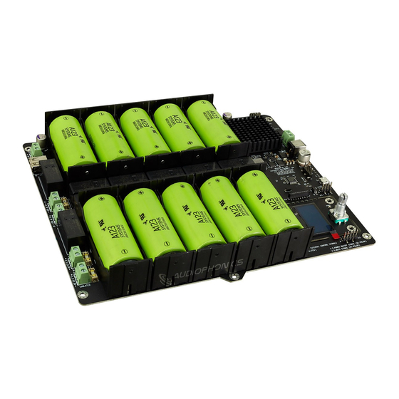
- Page 13 1. LifePO4 MkIII power supply. 2. LifePO4 MkIII power supply with battery holders and batteries Page 13 2019-05-10 iancanada.mail@gmail.com...
- Page 14 3. Upgrade to ultra capacitor power supply by UcMateConditioer, UcHybrid and UcAdpater 4. LifePO4 power supply integrates with DAC system Page 14 2019-05-10 iancanada.mail@gmail.com...
- Page 15 5. The connection between main PCB and OLED board when move OLED board externally © 2019 Ian Jin. The firmware code embedded in the LifePO4 MkIII battery power supply is the property of Ian Jin. You are granted a non-exclusive, non-transferable, non-sublicenseable, royalty-free right to use the LifePO4 MkIII battery power supply board solely for your own, non-commercial purposes.
Need help?
Do you have a question about the LifePO4 MkIII and is the answer not in the manual?
Questions and answers