
Related Manuals for Tractive Technology AUTO-BLiP


Summary of Contents for Tractive Technology AUTO-BLiP
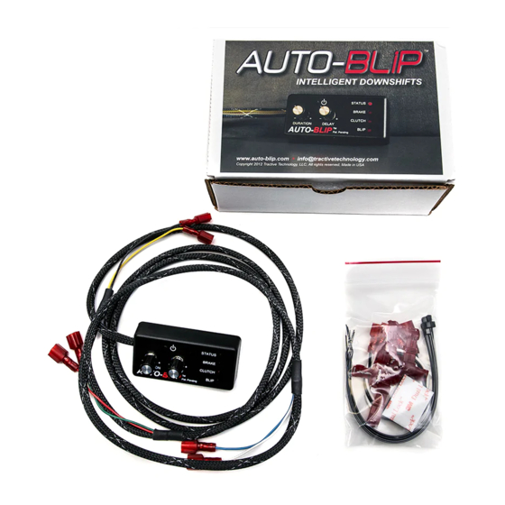
- Page 1 AUTO-BLiP INTELLIGENT DOWNSHIFTS www.AUTO-BLiP.com User Manual 2013+ DodgeViper Version 1.1 Copyright © 2012 Tractive Technology, LLC. All rights reserved. Page 1...
- Page 2 Changes to the settings in the AUTO-BLiP should only be made when it is safe to do so. The driver must remain attentive to driving the vehicle.
- Page 3 INTRODUCTION Congratulations on your purchase of the AUTO-BLiP for use on the Dodge Viper. Please take the time to read the entire instruction manual before attempting to install. DO NOT adjust the AUTO-BLiP until you have thoroughly read the instruction manual and the unit is fully installed and calibrated.
-
Page 4: Installation Instructions
#2 - middle Interlock Switch Directly below ECU harness exit from firewall. Under Dash- Light Negative (-) Black BLACK gray flat plug above brake pedal facing in-upwards on switch/plunger assembly. Copyright © 2012 Tractive Technology, LLC. All rights reserved. Page 4... - Page 5 Also, when you slide the AUTO-Blip connector onto the Wtap… it must be 100% pushed onto the tap and to its base. (This ensures a 100% clean connection between car and AUTO-Blip controller.
- Page 6 (BN/wh) & Wire#5 (WH/bn) are your Pedal Position Sensor #1 and #2 signals. These are shown above in the picture in actual physical positions. You can attach RED -or- GREEN to either. Copyright © 2012 Tractive Technology, LLC. All rights reserved. Page 6...
- Page 7 1 (Lt Blue). Install the outer wire for the positive 2 ALSO. Because these are adjacent to each other, attempt to shift/stack one above the other side-by-side. Copyright © 2012 Tractive Technology, LLC. All rights reserved. Page 7...
- Page 8 Then pass the harness thru the grommet while pried from the firewall. Push back into place afterwards. 1) Connect the YELLOW wire from the AB harness to the YELLOW w/orange stripe wire (#2 – middle of the three). Copyright © 2012 Tractive Technology, LLC. All rights reserved. Page 8...
-
Page 9: How It Works
7. The “BLIP” LED turns on when a throttle blip event occurs. Note: The AUTO-BLIP will automatically turn OFF after 6 hours of inactivity. It will remain OFF until the ON/OFF button is pressed or power to the unit is removed and re-applied. - Page 10 In order for your AUTO-BLiP unit to function properly, you must first perform the calibration sequence outlined in this section!!! 1. Turn on ignition, but do not start engine. AUTO-BLiP “STATUS” LED light will light up. If not, turn ignition off and verify the power supply and ground connectors are fully seated.
- Page 11 3. Be sure the unit has been calibrated, as outlined in the calibration section, according to your vehicle’s model and year. 4. Check harness for cuts, scrapes or abrasions. 5. Call technical support at 480-788-6748 Tractive Technology, LLC P.O. Box 93562 Phoenix, AZ 85070-3562 info@tractivetechnology.com Copyright © 2012 Tractive Technology, LLC. All rights reserved. Page 11...
- Page 12 If you discover a defect, Tractive Technology, LLC will, at its option, repair or replace this product with a new or reconditioned product at no charge to you, provided you return it during the warranty period, with transportation charges prepaid, to Tractive Technology, LLC.
Need help?
Do you have a question about the AUTO-BLiP and is the answer not in the manual?
Questions and answers