
Related Manuals for Mediso Nucline SPIRIT DH-V

Summary of Contents for Mediso Nucline SPIRIT DH-V
- Page 1 SPIRIT DH-V Nucline DUAL - HEAD SPECT AND WHOLE BODY DIGITAL GAMMA CAMERA Service Manual Revision 1.02...
- Page 2 Acquisition software release: v.7.03 The information and drawings set forth in this manual are the property of Mediso Ltd. No part of this document may be copied without the prior consent of Mediso Ltd. Manufacturer reserves the right to revise or update the contents of this manual due to modifications or improvements in the design of the equipment without obligation to notify any person or organization of such changes.
-
Page 3: Disclaimer
Disclaimer Mediso Ltd. and its official representatives may not be held responsible for personal injury or damage of any kind, expressed or implied, caused by, or emerging out of the use of this equipment, if equipment is not operated in adherence to operating and maintenance procedures set forth in this manual. - Page 4 ™ SPIRIT DH-V Service Manual Nucline Rev. Date Description Pages Approved 0000306 1.01 2006.05.05. New document DR interface panel 0000534 1.02 2006.07.12 77 - 85 changing 4/216 05/05/2006...
-
Page 5: Table Of Contents
Table of contents Disclaimer .............................. 3 Warning ..............................3 Electrical .............................. 3 Mechanical............................3 Radiation.............................. 3 Table of contents ...................... 5 Introduction ....................... 9 Scope of manual ..................... 10 Text Conventions Used in this Manual ..............11 Chapter 1. Safety and Regulatory Information........... 12 General Safety........................... - Page 6 ™ SPIRIT DH-V Service Manual Nucline Chapter 2. Camera overview................26 General description ........................26 2.1.1 System components ......................26 2.1.2 The system connections...................... 30 DH-V Gantry..........................32 2.2.1 Gantry hardware........................32 2.2.2 Gantry computer........................32 2.2.3 Detector heads ........................34 2.2.4 Gantry electronics........................
- Page 7 Directory of D:\ConsoleInstall.................... 155 4.5.5 Directory of D:\Delete Later....................157 4.5.6 Directory of D:\Img ......................157 4.5.7 Directory of D:\Mediso Upload ..................157 Chapter 5. Calibration ..................158 Applied devices ........................158 Process of calibration ......................159 5.2.1 Visual checking ......................... 159 5.2.2...
- Page 8 ™ SPIRIT DH-V Service Manual Nucline 5.2.12 PMT fine auto tuning with Tc99m..................168 5.2.13 Linearity calibration......................169 5.2.14 Intrinsic uniformity loading ....................174 5.2.15 Extrinsic uniformity loading....................175 Tests............................175 5.3.1 Intrinsic uniformity test....................... 175 5.3.2 Extrinsic uniformity test...................... 176 5.3.3 Energy resolution test......................
-
Page 9: Introduction
ECG gated acquisition capability which allows performing gated cardiac planar and gated cardiac SPECT studies. To enhance system features toward higher resolution imaging, Mediso presents the HR detectors option utilizing thinner NaI(Tl) detector crystal, most suitable under gamma photon ™... -
Page 10: Scope Of Manual
™ SPIRIT DH-V Service Manual Nucline Scope of manual ™ SPIRIT DH-V Acquisition Service Manual contains the following chapters: Nucline • Chapter 1 SAFETY AND REGULATORY INFORMATION - describes safety precautions and safety features. • Chapter 2 CAMERA OVERVIEW - contains system overview and the gantry operation modes. •... -
Page 11: Text Conventions Used In This Manual
Preface Text Conventions Used in this Manual The following conventions are used throughout the manual: • Special keys on keyboards, push-buttons and switches are indicated by bold-faced characters between angle brackets e.g. <Enter>, <Home Position>, <ON/OFF>. • Software buttons, called also Soft Keys are indicated by bold-faced characters between rectangular parentheses. -
Page 12: Chapter 1. Safety And Regulatory Information
4. The system in whole or in part should not be modified in any way without prior written approval by Mediso Medical Imaging Systems. Do not defeat any safety feature of the system. 5. The manufacturer or vendor of the equipment makes no representation, however, that the act of reading this manual renders the reader qualified to operate, test or calibrate the system. -
Page 13: Electrical Safety
3. For external connections, in order to maintain electrical safety, only the peripherals listed below, or others subsequently approved by Mediso Medical Imaging Systems, may be powered directly from the two output AC ™ SPIRIT sockets (marked by the "TO ACCESSORIES"... - Page 14 ™ SPIRIT DH-V Service Manual Nucline Rating USA Wall Plug European Wall Plug Current 12 A Voltage 115 VAC 230 VAC Cable diameter 0.5 inch (12 mm) 12 mm UL: “Hospital Grade” Meets local current and voltage Approvals ratings UL: “Hospital Only” The total current from the two output AC sockets should be less than 2A.
-
Page 15: Mechanical Safety
Gantry, or remove the power plug of the Electronics Rack from the wall outlet or uninterruptible power supply (UPS). 2. Notify your service representative or the Mediso Medical Imaging Systems office of the accident. 1.1.2 Mechanical Safety All moveable assemblies and supporting structures should be operated with care and routinely inspected. -
Page 16: Iec Symbols Used
™ SPIRIT DH-V Service Manual Nucline 1.2 IEC Symbols Used The system may have labels with one or more of the following symbols. These symbols indicate the IEC standards to which the system conforms. Symbol IEC Standard Alternating Current Protective Earthing Point ON / Power ON OFF / Power OFF Input Power... -
Page 17: Safety Devices
Safety and Regulatory Information 1.3 Safety Devices The imaging system has 2 basic types of safety devices: • Emergency Stop Button - used by the operator to halt the motorized system motions in cases where there is any possibility of danger to the patient. CAUTION Do not reset the button until the problem that necessitated its use is resolved. -
Page 18: Emergency Stop Button
™ SPIRIT DH-V Service Manual Nucline 1.3.1 Emergency Stop Button 1.3.1.1 Using the Emergency Stop • Use the emergency stop switches to stop all gantry, detector and imaging table motions in case of emergency. • The Emergency Stop button disconnects power to the motors controlling IMPORTANT movement, and all motions stop quickly. - Page 19 Safety and Regulatory Information all gantry motions stop to prevent the hazards of personal injury or equipment damage. However, collisions can occur in spite of this safety feature. Use increased care to prevent collisions in the following cases: • Positioning in MANUAL OVERRIDE mode. Collision detect is disabled when the system is in MANUAL OVERRIDE mode.
-
Page 20: Patient Safety And Emergency Egress
™ SPIRIT DH-V Service Manual Nucline 1.4 Patient Safety and Emergency Case 1.4.1 Patient Handling 1. During studies, monitor the patient during the entire scan to ensure that the patient maintains appropriate positioning relative to the Gantry. WARNING Unintended motion could cause injury. Never leave the patient unattended and always monitor the position of the patient and equipment during scan procedures. -
Page 21: Emergency Egress
Safety and Regulatory Information 1.4.3 Emergency Case System operation may be stopped due to power failure or a safety event (something coming into contact with the collision sensors), or the system may be halted by the operator in response to emergency conditions. In any case, the operator must first ensure that the patient is safely removed using the appropriate removal procedure. -
Page 22: Data Safety
™ SPIRIT DH-V Service Manual Nucline 1.5 Data Safety 1.5.1 General Verify and record the patient’s identification before starting a scan. CAUTION It is highly recommended to always make a backup of image data in case of possible medium breakdown. 1.5.2 Connectivity Always verify that the data transferred to another system has been correctly received. -
Page 23: Safety Labels
Safety and Regulatory Information 1.7 Safety Labels ® Type: Nucline Spirit(DHV) S/N.: DH-xxxxxx-V0 Unit: Collimator cart 2/1 0197 Manufactured: 2006 Made in Hungary Medical Diagnostics ® Type: Nucline Spirit(DHV) S/N.: DH-xxxxxx-V0 Unit: Collimator cart 2/2 0197 Manufactured: 2006 Made in Hungary Medical Diagnostics ®... -
Page 24: Regulatory Information
™ SPIRIT DH-V Service Manual Nucline LEADS ™ Type: Nucline RG TRIGGER S/N.: ECG-xxxxxx Unit: Patient Part Type BF Manufactured: 2006 Mediso Manufacturer: Ltd. Made in Hungary 1022 Budapest Alsótörökvész út 14. Phone: +36-1-399-3030 Medical Diagnostics ® Type: Nucline Spirit(DHV) S/N.: DH-xxxxxx-V0... -
Page 25: Usa Regulations
The camera has parts (WEEE), which must not get into the waste. Therefore at final removal the camera must be disassembled, and its parts must handle accurately. The Mediso takes over this disposal process free of charge, if you carry back the camera into its depot. -
Page 26: Chapter 2. Camera Overview
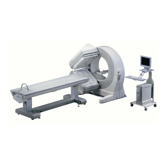
™ SPIRIT DH-V Service Manual Nucline Chapter 2. Camera overview 2.1 General description The DH-V gantry is designed to support and position two gamma camera detector heads weighing 600 kg each. The detector heads can move relative to each other. You can move them in and out to or from center of rotation (COR) and rotate them around the COR. - Page 27 Camera overview 2.1.1.2 Acquisition console 17” TFT color monitor Keyboard Emergency Stop Switch Mouse Nucline Electronics Rack Figure 2. Acquisition console 2.1.1.3 Imaging table Head holder (optional) Emergency Stop Switch Telescopes Imaging table with head holder assembled Figure 3. Revision 1.02 27/216...
- Page 28 ™ SPIRIT DH-V Service Manual Nucline ™ 2.1.1.4 Electronics Rack Nucline CD-ROM reader Front power switch Floppy disk drive Reset button Gantry service HDD LED Figure 10 Back side of console computer. Power LED ™ Electronics Rack Figure 4. Nucline 2.1.1.5 Handcontroller Ready LED E-STOP button...
- Page 29 Camera overview 2.1.1.6 Collimator and collimator cart ™ SPIRIT DH-V collimator Figure 6. Nucline Collimator cart Figure 7. Revision 1.02 29/216...
-
Page 30: The System Connections
™ SPIRIT DH-V Service Manual Nucline 2.1.2 The system connections The system components you saw in the last chapter have to be connected to each other to work properly. You can find a simplified system block diagram on the next page. - Page 31 Camera overview SPIRIT DH-V dual-head gamma camera - simplified system block diagram Nucline Performs motions Controls gantry hardware Network Reports position info Allows gantry calibration Color DISPLAY Hand- GANTRY monitor color monitor controller ECG module INPUT DEVICES Keyboard GANTRY GANTRY keyboard, mouse COMPUTER HARDWARE...
-
Page 32: Dh-V Gantry
™ SPIRIT DH-V Service Manual Nucline 2.2 DH-V Gantry 2.2.1 Gantry hardware New design, easy-to-install dual-detector gantry based on latest technology • 180° and 102° or 90° degree variable angle head positions with high precision positioning • small footprint robust mechanical design with improved safety factor •... - Page 33 Camera overview 2.2.2.3 Logging Gantry sends log messages continually to service serial port (19200,8,1,no flow control). Gantry sends the main status parameters as answer to any character coming in through this serial port. Press the <MODE>+<RESUME>+<MARK> buttons simultaneously. In this case the log messages will be written in file GANTRY.LOG, too.
-
Page 34: Detector Heads
™ SPIRIT DH-V Service Manual Nucline 2.2.3 Detector heads 2.2.3.1 Detectors Two newly developed rectangular jumbo FOV high stability detectors assembled with high optical and mechanical quality • NaI(Tl) scintillation crystal with special assembling case o size: 585 x 470 mm o thickness: 9.5 mm, 15.9 mm or 25 mm (pixelated) •... - Page 35 Camera overview Detector motions convention and range Figure 8. Buttons Function <E-Stop> (Emergency Stop) Stops all camera motions. Use this button in case of emergency. Ready LED Shows the system-status. If this LED blinks, the boot procedure is in progress or a failure could happen during system operations, otherwise if everything is all right the LED lights continuously.
-
Page 36: Acquisition Console
2.3 Acquisition console 2.3.1 Color monitor What kind of monitor can you connect? Mediso local distributor supports a 17” TFT color monitor with acquisition console assembled. You have to use CE and UL certificated monitor. How to install the monitor? At the beginning you get an installed monitor with your acquisition console. -
Page 37: Mouse
2.3.2 Mouse What kind of mouse can you connect? With the acquisition console Mediso supports you a mouse that is connected to console computer. That is a Genius Netscroll + PS/2 mouse.* If you have any problem with your mouse you can change it to a new one. -
Page 38: Keyboard
Nucline 2.3.3 Keyboard What kind of keyboard can you connect? Mediso supports a 101 buttons keyboard with acquisition console. You have to use CE and UL certificated keyboard. The default keyboard type is CHERRY with the following identifications: Typ. 35... -
Page 39: Nucline ™ Electronics Rack
Camera overview As a result of pressing <F9> a GIF image from the acquisition <F9> field will be created. You can use this function anywhere in the menu. Stop and Discard – Pressing <Shift>+<F9> during an acquisition allows you to stop the acquisition without storing the data already acquired. - Page 40 ™ SPIRIT DH-V Service Manual Nucline 2.3.4.1 QAD cards QAD cards are assembled in the Nucline Electronics Rack. There are two QAD cards in a Rack: QAD 1 and QAD 2. These cards transform the incoming analog signals to digital signals. QAD 1 and QAD 2 cards and connections Figure 9.
- Page 41 Camera overview 2.3.4.2 Back panel connections Back side of console computer Figure 10. Revision 1.0 41/216...
-
Page 42: Imaging Table
™ SPIRIT DH-V Service Manual Nucline 2.4 Imaging table 2.4.1 Telescopes 2 telescopes lift up and let down the imaging table. 4 bolts fix them both to the bed and to the bed-foot. CAUTION These bolts are screwed in aluminum, so you have to use a decreased momentum of 40 Nm. -
Page 43: Collimators And Collimator Carts
3.9 / 4.8 / 7.4* 1080 / 290 (1) Low Energy General Purpose collimator Mediso 09/2005. Specifications are subject to change. (2) Low Energy High Resolution collimator (3) Low Energy Ultra High Resolution collimator (4) Medium Energy General Purpose collimator... -
Page 44: Gantry Operation Modes
™ SPIRIT DH-V Service Manual Nucline 2.6 Gantry Operation Modes Browsing in menu system you have the opportunity to choose a menu item and start a predefined motion. In Normal Mode you can generally do the following: to step on the next menu item you have to push the <MODE>... -
Page 45: Collision Mode
Camera overview You can start the following procedures from Normal Mode: • Manual • Home • Remove patient • Heart Exam • Brain Exam • Collimator 1 Exchange • Collimator 2 Exchange • (Optional PREDEF) You can reach from Normal Mode: •... -
Page 46: Emergency Mode
™ SPIRIT DH-V Service Manual Nucline You can start the following procedures from Collision Mode: • Collision Override Mode To exit Collision Mode press the <MODE> button on the handcontroller and you will get to Collision Override Mode. You have to remove the object or if nothing touches the surface of touch plate press the <MODE>... -
Page 47: Service Mode
Camera overview 2.6.4 Service Mode Service Mode Figure 15. You can read more about Service Mode in chapter Hiba! A hivatkozási forrás nem található. Revision 1.0 47/216... -
Page 48: Calibration Mode
™ SPIRIT DH-V Service Manual Nucline 2.6.5 Calibration Mode Calibration Mode Figure 16. You can get to Calibration Mode: • From Service Mode (if you choose Calibration and press <START> button on the handcontroller.) To get to GR Calibration circle: •... -
Page 49: Error Mode
Camera overview 2.6.6 Error Mode Error Mode Figure 17. You get to Error Mode: • If a hardware or software error occurs. After solving the problem you have to press the <MODE> button on the handcontroller to get back to Normal Mode. Revision 1.0 49/216... -
Page 50: Chapter 3. Construction Guide
1. Rotate the detectors in 0° position Rotate detector heads in 0° position using handcontroller. If you are not able to use handcontroller, screw the spindle by hand using a crank you got from Mediso (Figure 19 Crank-hole and fixing screws of detector housing cove). - Page 51 Allen wrench you got from (Figure 22 Removing bearing housing cover). Mediso 3. Break the power supply towards gantry Break the power supply system towards gantry by turning off the console computer. (Shut down the console computer or push Emergency Stop button.)
- Page 52 ™ SPIRIT DH-V Service Manual Nucline Figure 21. Detector housing cover and the detector with housing cover removed 5. Remove the bearing housing cover Remove the bearing housing cover screwing off 4 pieces of M4 Pan Head Cross Recess bolt. Pan Head Cross Modifying detector Recess bolts...
- Page 53 Construction guide 7. Unscrew the belt tension bolt Unscrew the belt tension bolt until the belt gets loose. Belt tension bolt Loosing belt tension bolt Figure 23. 8. Remove motor holder Remove motor holder unscrewing 4 pieces of M8 bolts. M8 bolts Removing timing belt Figure 24.
- Page 54 ™ SPIRIT DH-V Service Manual Nucline Figure 25. Radius motor timing belt 9. Tip the motor Tip the motor to be able to remove the belt (Figure 24 Removing timing belt). 10. Install timing belt Install the new timing belt (Figure 25 Radius motor timing belt).
-
Page 55: Changing Radius Motor
Rotate detectors in 0 degrees position using handcontroller (Figure 18 0 degrees detector position). If you are not able to use handcontroller, screw the spindle by hand using a crank you got from Mediso (Figure 19 Crank-hole and fixing screws of detector housing cover). - Page 56 ™ SPIRIT DH-V Service Manual Nucline 2. Break the power supply towards gantry Break the power supply system towards gantry by turning off the console computer. (Shut down the console computer (Figure 20 a) Console computer turned on Console computer turned off) or push Emergency Stop button) 3.
-
Page 57: Changing Gantry Rotate Motor Timing Belt
1. Rotate the detectors in 315° position Rotate detectors to 315 degrees position using the handcontroller. If you are not able to use handcontroller, screw the spindle by hand using a crank you got from Mediso (Figure 19 Crank-hole and fixing screws of detector housing cover). -
Page 58: Changing Gantry Rotate Motor
™ SPIRIT DH-V Service Manual Nucline Plate fixing bolts (4 pcs) Motor fixing bolts (4 pcs) Belt tension modifier bolt Removing timing belt Figure 28. 6. Remove timing belt 7. Install new timing belt 8. Set belt tension While you screw the belt tension bolt, it lifts or lets down a plate you can fix to the motor holder plate. -
Page 59: Changing Gantry Rotate Servo Amplifier
Construction guide Gantry rotate motor Figure 29. 1. See in chapter 3.4 Changing gantry rotate motor timing belt, points 1-4. 2. Remove timing belt and after you unconnected cables to GR motor, remove it, too by screwing off 4 pieces of motor fixing bolts seen on Figure 28 Removing timing belt. - Page 60 ™ SPIRIT DH-V Service Manual Nucline Telescope fixing bolts Removing LIFT 3 Figure 30. LIFT 3 connector on the back side of gantry Figure 31. 3. Remove gantry back cover Remove gantry back cover holder bolts (9 pieces of M5). 4.
-
Page 61: Changing Pc 104 Module
Construction guide 13. Recover the power supply towards gantry Reconnect telescope 3 to connector signed by “LIFT 3”. 14. Test the system Test the whole system. If anything does not work properly, verify the cable connections again. CAUTION Until the gantry back cover is not replaced do not touch any electronics parts without breaking the power supply circuits towards gantry. - Page 62 ™ SPIRIT DH-V Service Manual Nucline 7. Install new PC104 module Install new module and fixing screws. 8. Reconnect electronic connectors to PC104 Reconnect electronic connectors to PC 104. Fix the long cables to PC 104 box. 9. Push back electronics holder plate 10.
-
Page 63: Changing Radius Controller Circuit
Rotate detector heads in 0° position using handcontroller (Figure 18 0 degrees detector position). If you are not able to use handcontroller, screw the spindle by hand using a crank you got from Mediso (Figure 19 Crank-hole and fixing screws of detector housing cover). -
Page 64: Changing Detector Cable
Rotate detector heads in 0° position using handcontroller Figure 18 0 degrees detector position). If you are not able to use handcontroller, screw the spindle by hand using a crank you got from Mediso (Figure 19 Crank-hole and fixing screws of detector housing cover). - Page 65 Construction guide 6. Dissolve cable end connections Dissolve cable end connections on the detector side. 7. Remove cable fixing screws (3 pieces). 8. Pull out cable end through the hole on the back side of detector housing Gantry cable hole on Gantry cable holes on detector holder gantry housing front...
-
Page 66: Changing Collimator Lock Panel
Rotate detector heads in 0° position using handcontroller (Figure 18 0 degrees detector position). If you are not able to use handcontroller, screw the spindle by hand using a crank you got from Mediso (Figure 19 Crank-hole and fixing screws of detector housing cover). - Page 67 Construction guide 3. Break the power supply towards gantry Break the power supply system towards gantry by turning off the console computer. (Shut down the console computer (Figure 20 a) Console computer turned on Console computer turned off) or push Emergency Stop button). 4.
-
Page 68: Collimator Cart Adjustment
™ SPIRIT DH-V Service Manual Nucline 3.11 Collimator cart adjustment Required tools: • Fork wrench (7, 17, 24, 27) • Allen wrench kit • Drill (10mm) IMPORTANT Check if the camera is in water-level for both sides. 1. Set the head to collimator exchange position. 2. - Page 69 Construction guide Figure 37. Screw-threaded rods in the collimator cart 4. Set the collimator cart fastening drift to roughly the middle position. To do it, loosen the two bolts. Collimator cart fixing drift Figure 38. 5. Loosen the collimator cart’s height adjusting bolts which can be found on the lower side of the cart (2 at each side).
- Page 70 ™ SPIRIT DH-V Service Manual Nucline Collimator height adjustment bolts Figure 39. 6. Measure the height of the bottom positioning drifts hole on the head. Set the cart to this height with the bolts. Fasten the bolts with hand. Take care, that the two sides of the cart must be exactly in a same height.
- Page 71 Construction guide 10. Near the head to the cart very slowly. You have to watch it constantly to avoid equipment damage. The detector head connect the collimator in 6 points (front – 1/1 above / below, back – 2/2 above / below)! You have to look out all six connecting points simultaneously. Figure 41.
- Page 72 ™ SPIRIT DH-V Service Manual Nucline Blocking lever tongue and groove Figure 43. CAUTION If you do not stop the head in time, it could break the cart! 13. Fasten the 4 screw-threaded rods (Figure 37 Screw-threaded rods in the collimator cart).
- Page 73 Construction guide 14. Sign the collimator cart fixing drift position on the weigh lifting plate (Figure 38 Collimator cart fixing drift). 15. Choose Service > Set exchange pos and then press <START>. 16. “Save the current pos? Press MARK” Press <MARK> to save the head positions. 17.
-
Page 74: Head Removal
™ SPIRIT DH-V Service Manual Nucline 3.12 Head removal Required tools • Allen wrench kit • Screwdriver kit • Cut nippers • Cable wrapping • Pallet jack 1. As a first step please rotate the Head to horizontal position (before doing anything else). The collimators have to be installed! Detector Heads in horizontal position Figure 45. - Page 75 Construction guide Cable set Figure 47. Motor connections and 60V on the power filter Figure 48. Signal and power cable on the front board Figure 49. Revision 1.0 75/216...
- Page 76 ™ SPIRIT DH-V Service Manual Nucline Detector radius interface Figure 50. Figure 51. Grounding points Grounding points Figure 52. 76/216 05/05/2006...
- Page 77 Construction guide Power fan connections Figure 53. Connections on the detector radius interface panel Figure 54. At cameras released after 2006.04, the detector radius interface panel had been changed for the easier operating and servicing. The two panels are compatible with each other, and could be exchange.
- Page 78 ™ SPIRIT DH-V Service Manual Nucline 4. Cut all plastic fixing belts, as shown on Figure Cut the plastic fixing belts Figure 56. 78/216 05/05/2006...
- Page 79 Construction guide 5. Pull all the cables aside, as you freed up the appropriate endings. The results should be similar to the set-up displayed on Figure Figure 57. Pull out all the cables aside 6. Screw out the four fixing bolts on both sides. Screw out the fixing bolts on right side.
- Page 80 ™ SPIRIT DH-V Service Manual Nucline Figure 59. Fix up the metal plate on the right side Figure 60. Fix up the metal plate on the left side 8. Rotate the Head to the position displayed on Figure 61. The rail should be visible exactly 6 centimeters.
- Page 81 Construction guide The rail is visible exactly 6cm Figure 62. 9. Rotate the Head clockwise to 0 degrees, so it is positioned downwards. If the gantry doesn’t work, you can turn with the drill, but than be very careful for right direction (You must move clockwise!) Rotate the Head clockwise Figure 63.
- Page 82 ™ SPIRIT DH-V Service Manual Nucline 10. Shift the pallet that you received by post under the rotated Head. Figure 65. Insert the pallet under the detector 11. Push a Pallet jack under the pallet and lift it up so the Head just seizes. 12.
-
Page 83: Head Installation
Construction guide Figure 68. Pull out the detector head 14. Now you can start removing the Detector Head 2. You just have to repeat the steps from 1 to 9. on Head 2. When complete these steps rotate the head Counterclockwise!!! Then repeat the steps from 11 to 14 on Head 2. - Page 84 ™ SPIRIT DH-V Service Manual Nucline Figure 70. Positioner spikes 5. Each side is fixed with 7 bolts. 4 for the exterior part (8x25) and 3 for the interior part (8x20) as shown in the next Figure. 8x25 8x20 Fixing bolts Figure 71.
- Page 85 Construction guide The following pictures show the detector panels’ connections. Figure 72. Power filter and detector radius interface connections (front view) Power filter and detector radius interface connections (top view) Figure 73. Power filter and detector radius interface connections (rear view) Figure 74.
- Page 86 ™ SPIRIT DH-V Service Manual Nucline Figure 75. Power filter and detector radius interface connections (side view) Grounding points and power fan connections Figure 76. Figure 77. Detector in final position 86/216 05/05/2006...
- Page 87 Construction guide At cameras released after 2006.04, the detector radius interface panel had been changed for the easier operating and servicing. The two panels are compatible with each other, and could be exchange. The next figures show the new panel’s connections.
- Page 88 ™ SPIRIT DH-V Service Manual Nucline DR interface – Limit Figure 81. DR interface – Camlock2 Figure 82. DR interface – Safety Figure 83. 88/216 05/05/2006...
- Page 89 Construction guide DR interface – Coll. Sens. Figure 84. Figure 85. DR interface – CAN DR interface – Camlock1 Figure 86. Revision 1.0 89/216...
- Page 90 ™ SPIRIT DH-V Service Manual Nucline Figure 87. Motor – Encoder Lock panel power cable connection Figure 88. Front panel connection Figure 89. The number F305 connection shouldn’t connect to anywhere, it is designed for future function. 90/216 05/05/2006...
-
Page 91: Amc Servo Burning
Construction guide 3.14 AMC servo burning Necessary tools for work: • Special cable, which has a 9pin DSUB female connector and two 44pin DSUB (a female and a male) • Supply cable is a simple two wire cable with a switch. •... - Page 92 ™ SPIRIT DH-V Service Manual Nucline 3. Console PC a. Start the "start_connection.bat" on console computer (located in c:\gantry\service\jtec directory) and reset the Gantry Computer. It will open a new window and some minutes later you should to see the A:\>. 4.
- Page 93 Construction guide e. Switch on the “supply cable” (keep the short circuit). Wait approx. 5 seconds and remove the short circuit. If the status LED is not blinking (continuously red), it is ok, otherwise switch off the “supply cable” and repeat steps from the Restart point. 5.
-
Page 94: Chapter 4. Software Adjustment
™ SPIRIT DH-V Service Manual Nucline Chapter 4. Software adjustment This chapter describes the files, installed to the console PC. It gives sort information about files that are important for the service procedures. The system files, that can’t be modified, only have the names and the locations. -
Page 95: Installation Of The Operating System Of The Console Electronics
Software adjustment 4.1 Installation of the operating system of the Console electronics 4.1.1 Preparation of the Console electronic rack 4.1.2 Preparing the completely new Console computer to start the installation of the OS This time no any of the Gantry HW components including the communication cables are connected to the console computer. - Page 96 ™ SPIRIT DH-V Service Manual Nucline CMOS Setup Utility Figure 94. 1. Validate or disable modifications • It is always possible to escape from the CMOS Setup Utility instead of saving a wrong modification of the BIOS setting. Do that: •...
-
Page 97: Checking And Modifying The Bios
Software adjustment Figure 96. Save and Exit 2. Setting of the actual date and time: • Highlight the Standard CMOS Features line and press <Enter>. • Check the time setting and try to modify its values even to get experiments in the modification of the BIOS table. - Page 98 ™ SPIRIT DH-V Service Manual Nucline Variables in the Standard CMOS Features page Figure 97. 2. Advanced BIOS Features • Highlight the line titled and press <Enter> on it (Figure 98. Advanced BIOS Features). Advanced BIOS Features Figure 98. • Press <Enter> on the Hard disk Boot priority and observe that in the first line the title of the HDD is displayed (Figure 99.
- Page 99 Software adjustment Figure 99. Hard Disk Boot Priority • First Boot Device should be the USB - CDROM. Press <Enter> on the bracketed of the First Boot Device. Normally an USB-CDROM drive is supplied with the DH-V Console systems. Use the arrow of the keyboard to move the dot down to the bracket of USB - CDROM.
- Page 100 ™ SPIRIT DH-V Service Manual Nucline CPU Hyper-Threading Figure 101. • On-Chip Frame Buffer Size should be 16MB. 3. Save & Exit Setup (Figure 102.) • Highlight the Save and Exit line and push <Enter>. Type <Y> and <Enter>.In this case a previously composed version will not be saved. Figure 102.
-
Page 101: Windows 2000 Install
• There is no easy way to save the actual settings of the BIOS functioning. That is why the necessary modifications had been discussed from page to page. To reset the BIOS according to the Mediso setting is possible on the way of comparing the existing pages with the pages copied into the Troubleshooting section of this chapter. - Page 102 ™ SPIRIT DH-V Service Manual Nucline Boot from USB-CDROM Figure 104. • Switch Off the Console Computer. Restarting the computer is not enough to validate this setting. • Switch ON the computer. Even the old Desktop will appearing on the screen the Installation is Starting.
- Page 103 Software adjustment Figure 105. Windows 2000 Welcome to Setup To set up Windows 2000 now, press: <ENTER>. To repair a windows 2000 installation, press: <R>. To quit Setup without installing Windows 2000, press: <F3>. • Press <ENTER> and wait until the Windows 2000 Licensing Agreement appears (Figure 106.).
- Page 104 ™ SPIRIT DH-V Service Manual Nucline Repair or continue Figure 107. • Press <ESC>. • If the disk already contains partitions typing <D> on it the existing partition will be deleted. (Figure 108. Existing partitions). About other opportunities we will not discuss because a quite new installation will be performed. Figure 108.
- Page 105 Software adjustment Confirming deleting partition D: Figure 110. To set up Windows 2000 on the selected item, press <ENTER>. To create a partition in the unpartitioned space, press <C>. To delete the selected partition, press <D>. Setup, create or delete Figure 111.
- Page 106 ™ SPIRIT DH-V Service Manual Nucline Create new partition Figure 112. • Write this value (30000) and press <ENTER> (Figure 112. Create new partition). 29 996 appears as a possible size for it. Press <ENTER>. • The screen displays the planned partitions. The planned partitions Figure 113.
- Page 107 Software adjustment Figure 115. Formatting drive C • Format C: drive is running. • C: drive will be dedicated as Partition 1 (New Raw). That means a 10 min process. (Figure 115 Formatting drive C). After that copying files takes another 2 minutes and the computer will restart.
- Page 108 Nucline Name and organization Figure 117. Name: DHV Represents the computer on the network Organization: Mediso Used as: Personalize Your Software Table 3. • The Product key is the number on the ticket supplied with the Microsoft Windows 2000 Installations Program (Figure 118.
- Page 109 Software adjustment Figure 119. Computer name and Administrator Password Used as: name on the network Console install can modify it. Ser. No Computer name: DHV goes to the cam cfg. important in the acquired images. Used as: to allow access of any system tools and settings.
- Page 110 ™ SPIRIT DH-V Service Manual Nucline • After the restarting process the Network Identification Wizard appears on the screen. (Figure 121) Welcome to the Network Identification Wizard Figure 121. • To continue, click [Next]>. Figure 122. Who will use this computer •...
- Page 111 Software adjustment Figure 123. Select the upper option to force users to enter user name and password • To complete the Network Identification Wizard click on [Finish]. If it is recommended to define users immediately, choose the second option and do the following: •...
- Page 112 ™ SPIRIT DH-V Service Manual Nucline How to modify User accounts Figure 124. Administrator Properties Figure 125. 112/216 05/05/2006...
- Page 113 Software adjustment Guest Properties Figure 126. • To modify User accounts do the following: Click on the My Computer icon on the desktop by right mouse button, click on Manage > Local users and groups > Users. Right click on user name you want to modify and select Properties.
-
Page 114: Console Software Installation Procedure
™ SPIRIT DH-V Service Manual Nucline • Start computer again and referring to the beginning of section (4.1.4 Preparation of the Basic Input / Output System (BIOS)) and set the HDD as First Boot Device and the USB-CDROM as Second Boot Device (Figure 104. - Page 115 Software adjustment Change drive letter Figure 130. 5. Assign a drive letter from the scroll down list. Select <E> and OK to confirm the selection. Figure 131. Assign drive letter 6. Now click to the Free space field with right button and to New Logical Drive (Figure 128.
- Page 116 ™ SPIRIT DH-V Service Manual Nucline 10. Determine the size of partition D: and then click on [Next]. Size of the planned D: partition Figure 132. 11. Write a new Volume label. Perform a Quick format in NTFS File system. Click [Next]. Quick format partition D: Figure 133.
-
Page 117: Start The Installation Process
Software adjustment 12. Within a short time formatting is ready. New partition is correct. Completing new partition Figure 134. 4.3.1 Start the installation process ™ SPIRIT DH-V camera acquisition software and 1. Insert the CD labeled " Nucline service tools" to your PC’s DVD drive. 2. - Page 118 ™ SPIRIT DH-V Service Manual Nucline Figure 136. License agreement 4. Select: ”I accept the terms of the license agreement” and then click [Next]. The console setup types box appears. Console Setup types Figure 137. 118/216 05/05/2006...
-
Page 119: Setup New Camera Application
Software adjustment 5. Choose one of the following selections: Setup type Installation Type Setup new Camera application First complete Console program installation. If you have already an installed Console Backup application application on your system and you intend to save a backup copy from it. If you have already saved a copy and you intend to restore a backup. - Page 120 ™ SPIRIT DH-V Service Manual Nucline Configure camera and system components Figure 139. If you have selected "Setup new Camera application" you need to configure all the fields in the "Configure camera and system components" box. NOTE If you have selected "Setup new Camera application" some buttons and fields are disabled (Net details, Processing system and Information system).
- Page 121 Software adjustment One of the following: AD type: • QADB Note: Driver will be installed in spite of the device is not inserted into the system. The • QADC program does not recognize the type of • QADD ADC. Specify the type of ADC used. QADE •...
- Page 122 ™ SPIRIT DH-V Service Manual Nucline Camera Calibration Settings Adjustments Figure 140. 5. Selecting the most convenient method for calibration click OK and the program returns to the Console elements table. Advanced settings Figure 141. 6. Two variables can be adjusted: •...
- Page 123 Software adjustment Figure 142. Ready to Install the Program 4.3.2.1 Installing the console components. 1. Click [Install] to begin the installation. Performing the DH-V Setup the Console components installation is running. Console components installation is running Figure 143. 2. As it is mentioned the Installation program does not recognize the type and the presence of ECG and QAD devices.
- Page 124 ™ SPIRIT DH-V Service Manual Nucline 4.3.2.2 Installing non console components The following components will be used by the DH-V program: • Motherboard drivers • Video driver • Modem driver • VNC software • InCD software • Acrobat Reader • Accept incoming connection. You do not have to choose any of the following Non console elements.
- Page 125 Software adjustment Non console elements. Chipset Software Figure 146. 3. Click [Next]. License Agreement appears. Answer [Yes]. 4. Chipset Info screen appears. Chipset Info Figure 147. 5. Click [Next]. The installation is running. Finally the program asks about do or not restarts the computer. Select: No, I will restart my computer later.
- Page 126 ™ SPIRIT DH-V Service Manual Nucline Figure 148. Do not restart 6. Click [Finish]. 7. Different components are displayed. Wait until any message appears. 8. But (as it was already determined during the Windows installation) the Realtek AC97 Audio is not compatible. The warning is displayed repeatedly.
- Page 127 Software adjustment 4.3.2.2.2 Video driver install Video driver install Figure 150. 4.3.2.2.3 Modem driver install Modem driver install Figure 151. Revision 1.0 127/216...
- Page 128 ™ SPIRIT DH-V Service Manual Nucline 4.3.2.2.4 VNC software install VNC software install Figure 152. NOTE Driver for VNC is free software. 1. Click [Next] to confirm installation. VNC Setup Wizard appears. [Next]. License Agreement appears. [Yes]. Allow C:\Program files as destination.
- Page 129 Software adjustment 4.3.2.2.5 InCD software install InCD software install Figure 153. 1. Clicking [Next] jump to the InCD component. 2. InCD Updater appears. 3. [Next]. License agreement appears. [I accept] and [Next]. 4. Installation running than click [Finish]. 4.3.2.2.6 Acrobat reader install Acrobat reader install Figure 154.
-
Page 130: Modify Settings
™ SPIRIT DH-V Service Manual Nucline Installation method of the Accept incoming connection option is a function of NOTE the system realized. Accept incoming connection Figure 155. 1. Read the text and proceed it on the way of Settings / Network and dial-up connections / Make new connection. - Page 131 7. Factory specific settings means that before packing the Gamma camera a Factory backup is prepared on a Medserver computer of the manufacturer but a CD is completed with the same structure, too. This is the duty of Mediso. 8. [Ok] will confirm the new settings.
- Page 132 ™ SPIRIT DH-V Service Manual Nucline Modify settings Figure 158. 9. Now several rows are allowed to change. Refer to: Table 7. Fields to determine the Console configuration. 10. Processing systems can be selected from the scroll-down list. Browse the existing data processing system.
- Page 133 Software adjustment Figure 160. Processing system settings 11. Output of data transfer dedicated as a Drive (i.e. I:) can be inserted into the existing drive list. If the planned Processing system already connected to the Console computer, and its data input folder is visible on the Network place list it can be matched with the output drive letter.
- Page 134 ™ SPIRIT DH-V Service Manual Nucline 14. Press [Next] on the Configure Console elements list (Figure 161. Specify information system). Start modification Figure 162. 15. Click [Modify] to begin modification. A message appears: 16. Press [Yes]. Reboot. Figure 163. 17. Press [Yes] to reboot. 134/216 05/05/2006...
-
Page 135: Backup Application
Software adjustment 4.3.4 Backup application Setup types Figure 164. Figure 165. Backup components Revision 1.0 135/216... - Page 136 ™ SPIRIT DH-V Service Manual Nucline Site backup Figure 166. Backup directory Figure 167. Confirm backup destination. Figure 168. 136/216 05/05/2006...
- Page 137 Software adjustment Backup Figure 169. Backup is finished Figure 170. Restore application Figure 171. Revision 1.0 137/216...
- Page 138 ™ SPIRIT DH-V Service Manual Nucline Figure 172. Restore components Figure 173. Backup source directory Restore camera components. Figure 174. 138/216 05/05/2006...
- Page 139 Software adjustment Restore network settings. Figure 175. Restore desktop files. Figure 176. Restore camera files. Figure 177. Figure 178. Restore images. Restore gantry files. Figure 179. Figure 180. Components are restored. Revision 1.0 139/216...
-
Page 140: Until You Reach The Finish
™ SPIRIT DH-V Service Manual Nucline 4.3.5 Until you reach the finish. At the end of the installation you will be asked to restart your PC. After your PC is again restarted you are ready to start the Console application. Double click the DH-V Console icon on your desktop 1. -
Page 141: Host Side (Left Side)
Software adjustment An explorer surface appears on your display. GantryUpgrade display Figure 182. 4.4.2 Host side (left side) The default drive in this section is: C:\Gantry 4.4.2.1 Commands Download (F5): This command copies the assigned file(s) to the actual drive on the gantry side (right side). -
Page 142: How To Modify Cfg Files
™ SPIRIT DH-V Service Manual Nucline For the first time this side is empty until you click on Refresh icon. The gantry software uses the files on this drive. 4.4.3.1 Commands Refresh: Shows you the files of actual folder. Upload (F5): Uploads the assigned file(s) to the folder on the left side. -
Page 143: How To Create Log File
Software adjustment 4.4.5 How to create LOG file 4.4.5.1 Creating LOG file using serial port. Connect the service computer to gantry PC using a serial link cable (you can find the connection place on the back side of gantry behind the left sided cover plate. -
Page 144: Folders After Installation
Generated by the operating system Folders after installation: <DIR> c:\console <DIR> c:\gantry <DIR> D:\CameraBackup <DIR> D:\ConsoleInstall <DIR> D:\Delete Later <DIR> D:\Img <DIR> D:\Mediso Upload 4.5.1 Directory of c:\console • AUTOEXEC.NT • CONFIG.NT • console.bat Console starter bat file • wconsole.bat • <DIR>... - Page 145 Software adjustment • <DIR> Temporary files folder 4.5.1.1 Directory of c:\console\bin • CONSOLE.MNU Console program menu text • CONSOLE.MSG Console program messages • CQ4_68NT.EXE Calibration program • ENERGY5.EXE Energy table viewer • Initialising QAD card.lnk • KEPNEZW.EXE Table viewer • LINCALC.EXE Linearity table counter •...
- Page 146 ™ SPIRIT DH-V Service Manual Nucline 4.5.1.4.2 Directory of c:\console\Drivers\EkgXP • Ekgstub0.sys • ekgvdd0.dll • ekgxp.inf • EKGXP.sys • readme.txt 4.5.1.4.3 Directory of c:\console\Drivers\Isaio • CONFIG.NT • ISAIODSD.SYS • ISAIOKMD.INF • ISAIOKMD.INI • isaiokmd.sys • isaiovdd.dll • readme 4.5.1.4.4 Directory of c:\console\Drivers\Modem •...
- Page 147 Software adjustment 4.5.1.4.5 Directory of c:\console\Drivers\Qad • CONFIG.NT • QAD2K-1.inf • QAD2K-3.inf • QAD2K.sys • QADSTUB0.SYS • QADSTUB1.SYS • QADSTUB2.SYS • QADSTUB3.SYS • qadvdd0.dll • qadvdd1.dll • qadvdd2.dll • qadvdd3.dll • readme.txt 4.5.1.4.6 Directory of c:\console\Drivers\QadXP • Config.nt • Qadstub0.sys •...
- Page 148 ™ SPIRIT DH-V Service Manual Nucline • CameraCfg.xls Herefrom takes the camera.cfg values during installation • DOS4GW.EXE DOS extender • install.ini • installd.ini • MDS.dll • Readme.txt • setup.exe • store.dll • Update.exe • worklist.dll 4.5.1.7 Directory of c:\console\Lin • cs_x.dat •...
- Page 149 Software adjustment • test_xh2.k • test_yh2.k • <DIR> FACTORY Factory base load • <DIR> UPLOAD Further load 4.5.1.8.1 Directory of c:\console\Lin2\FACTORY • cs_x.dat • cs_y.dat • linx.cfg • liny.cfg • LIN_X1.TBL X direction linearity table • LIN_Y1.TBL Y direction linearity table 4.5.1.8.2 Directory of c:\console\Lin2\UPLOAD •...
- Page 150 • KEPNEZ_E.1.ICO • KEPNEZ_E.2.ICO • KEPNEZ_E.3.ICO • KEPNEZ_E.4.ICO • LINCALC.PIF • LINEARITY.ICO • LINEARITY_1.ICO • LINEARITY_2.ICO • LINEARITY_3.ICO • LINEARITY_4.ICO • Mediso.ICO • MULPMTBLACK_1.ICO • MULPMTBLACK_2.ICO • MULPMTBLACK_3.ICO • MULPMTBLACK_4.ICO • MULPMT_1.ICO • MULPMT_2.ICO • MULPMT_3.ICO • MULPMT_4.ICO • PILE_UP01B.ICO •...
- Page 151 Software adjustment 4.5.1.10 Directory of c:\console\Pmt Head 1 PMT gain log. 4.5.1.11 Directory of c:\console\Pmt2 Head 2 PMT gain log. 4.5.1.12 Directory of c:\console\Print • PRINT.DLL Print dll 4.5.1.13 Directory of c:\console\Remain Haven’t sent images. 4.5.1.14 Directory of c:\console\Reports The Console makes here the log files. 4.5.1.15 Directory of c:\console\resource •...
- Page 152 ™ SPIRIT DH-V Service Manual Nucline • D_KAM2.CFG Head 2 Front, AD config. • Iv45.v2 Head 2, number 45 SMRD’s Pileup vector table for Z • IV45.VEK Head 1, number 45 SMRD’s Pileup vector table for Z • Iv45x.v2 Head 2, number 45 SMRD’s Pileup vector table for X,Y •...
-
Page 153: Directory Of C:\Gantry
Software adjustment 4.5.1.18.3 Directory of c:\console\TBLS\TC-99M.2 • unif.img • unif.tbl unif table • unifbase.tbl • uniimg.dat • uniimg.img • unitst.dat • unitst.img 4.5.1.18.4 Directory of c:\console\TBLS\TL-201 • unif.img • unif.tbl unif table • uniimg.dat • uniimg.img • unitst.dat • unitst.img 4.5.1.19 Directory of c:\console\Tbls2 Same as Console\Tbls. - Page 154 ™ SPIRIT DH-V Service Manual Nucline • CAMERA.CFG Gantry configuration file (copy) • COLL_ID.CFG Collimator ID’s config file (copy) • DHV_man.bmp Gantry window for normal mode • DHV_mtr.bmp Gantry window for Manual Override mode • DHV_sens.bmp Gantry window for Service mode •...
-
Page 155: Directory Of D:\Camerabackup
Software adjustment • MSFLXGRD.OCX • msscript.ocx • msvbvm60.dll • oleaut32.dll • olepro32.dll • RICHTX32.OCX • selfregister.exe • stdole2.tlb • TABCTL32.OCX 4.5.2.2 Directory of c:\gantry\Service • <DIR> jtec 4.5.2.2.1 Directory of c:\gantry\Service\jtec • conn.bat accessory scripts for start_connection.bat • floppy.img minimal gantry op.system COM1 •... - Page 156 ™ SPIRIT DH-V Service Manual Nucline • Readme.txt • setup.boot • setup.exe • setup.ini • setup.inx • SETUP2.exe 4.5.4.1 Directory of d:\ConsoleInstall\console • <DIR> Desktop • <DIR> install 4.5.4.1.1 Directory of d:\ConsoleInstall\console\Desktop • Console DHV.pif • <DIR> For Service Only Directory of d:\ConsoleInstall\console\Desktop\For Service Only •...
-
Page 157: Directory Of D:\Delete Later
Software adjustment • store.dll • Update.exe • worklist.dll 4.5.5 Directory of D:\Delete Later 4.5.6 Directory of D:\Img The console program saves the images here. 4.5.7 Directory of D:\Mediso Upload Revision 1.0 157/216... -
Page 158: Chapter 5. Calibration
™ SPIRIT DH-V Service Manual Nucline Chapter 5. Calibration 5.1 Applied devices • Co57 point source • Ba133, Ga67, Tc99m isotopes • Source holders (Figure 183-184) • Digital multimeter • 50 Mhz oscilloscope • Linearity phantom(s), ring phantom • Screw driver Figure 183. -
Page 159: Process Of Calibration
Calibration 5.2 Process of calibration • The indicated voltages are to be understood between the test point and the system grounding. • If the camera has got more than one head, you have to complete the calibration and the test to each head. •... - Page 160 ™ SPIRIT DH-V Service Manual Nucline Launch the following instructions: • 7: EEPROM programming • 6: Set the digital potentiometers to centre position • 19: Switch the signal generator on 3. Connect the oscilloscope (DC; 500mV (DIV; 0,2uS) to the TP5 point which can be found on the first pre-amplifier.
-
Page 161: The Pmt Gain Settings
Calibration TP1-TP4 and ZEOUT points Figure 187. 5.2.4 The PMT gain settings 1. Run the Serial com. Head1 / Head2 program which can be found in For Service Only folder. • 7: EEPROM programming • 6: Set the digit. potentiometers to the center 2. -
Page 162: Direction Gain Settings
™ SPIRIT DH-V Service Manual Nucline 5.2.5 Direction gain settings 1. Run the Calibrat Head1 / Head2 program which can be found in For Service Only folder. Choose Acquisition. 2. Move the Co57 up – down, and left – right. Check the moving on the monitor (don’t forget, that the left direction on the monitor is right!). - Page 163 Calibration Tc99m – 140KeV Figure 188. 4. Press <F3>. 5. With modifying the high-voltage, set the Tc99m–to 70KeV. Tc99m – 70KeV Figure 189. 6. Press <F3>. 7. With modifying the high-voltage, set the Tc99m–to 400KeV. Revision 1.0 163/216...
-
Page 164: The Spectrum Calibration
™ SPIRIT DH-V Service Manual Nucline Figure 190. Tc99m – 400KeV 8. Press <F3>, wait until the end of the calculation and then save the results. 9. “Second HV calibration?” Press <n> for no! 5.2.8 The spectrum calibration • required isotopes: BA133, Ga67 in special holder (1-2MBq;... -
Page 165: Pmt Coarse Auto Tuning With Tc99M
Calibration 1. Set the detectors to 102° position. 2. Place the Ba133 or the Ga67 isotopes in front of the detector (min 2 FOV). 3. Set the used Isotope ID: SP-BA. 4. Press <F3> to set the ZE offset to zero. 5. -
Page 166: Measuring And Fixing Of The A/D Card Offset
™ SPIRIT DH-V Service Manual Nucline 5.2.10 Measuring and fixing of the A/D card offset • The measurement does not require any isotope at all! System > Service > Measure & Store Offset + Digital Front „Measure and store..?”-> Yes 5.2.11 Spatial registration •... - Page 167 Calibration 3. Set the used Isotope ID. 4. Press <F3>. 5. Place the source into the left sign of the detector map (as shown in the next figure), you can see it on the left side of the image. 6. In case of Tc99m set total count to 2000 kcount. Spatial registration in the left side Figure 195.
-
Page 168: Pmt Fine Auto Tuning With Tc99M
™ SPIRIT DH-V Service Manual Nucline Figure 197. Spatial registration in the upper side 12. In case of Tc99m set total count to 2000 kcount. 13. <F3>. 14. Place the source into the lower sign of the detector map (as shown in the next figure) you can see it on the lower side of the image. -
Page 169: Linearity Calibration
Calibration Fine auto tuning Figure 199. 1. Remove all other isotopes and free activity from the room! 2. Place the Tc99m isotope in front of the detector (min 2 FOV). 3. Check the activity: it should be between 20-40 kcount. In other cases you can reach the desired value by modifying the detector –source distance, or the activity of the source. - Page 170 ™ SPIRIT DH-V Service Manual Nucline Figure 201. Linearity image X direction 1. Paste the body contour’s contact element with a piece of binding tape. Body contour’s contact element Figure 202. 2. Place the linearity phantom (and the Ring phantom) to the detector in X direction (the linearity image always consists of vertical and nearly parallel lines, Figure 201).
- Page 171 Calibration 6. Run the acquisition (<F3>), wait till the operation completes, and than rotate the phantom with 90° (Y direction) (the Y directioned linearity image in every cases consists of horizontal and nearly parallel lines Figure 203.) 7. The View ID1 field switches to LINEARITY Y automatically. Start the acquisition with <F3>.
- Page 172 ™ SPIRIT DH-V Service Manual Nucline X direction correction Figure 204. • F: filter • S: saving 11. Repeat the previous procedure with the Y image. • Y: choosing the Y image • L: loading the image • F: filter •...
- Page 173 Calibration The parallel lines cross each other, or they inflexion at the edge of the image. Move the cursor with the cursor arrows to that point, wherefrom the track line deviate from the acquired line. Cut the wrong part of the track line with <Delete>. (Note, that the program always deletes the shorter part of the whole track line!) When all the wrong part had been deleted, switch to insert mode by pressing <Insert>.
-
Page 174: Intrinsic Uniformity Loading
™ SPIRIT DH-V Service Manual Nucline 5.2.14 Intrinsic uniformity loading • required isotope: Tc99m (activity: 15-30MBq) • source holder Console > Acquire Patient Study > User Calibrations > X1 FLOOD+E_CAL_INT Intrinsic uniformity loading Figure 207. 1. Remove all other isotopes and free activity from the room! 2. -
Page 175: Extrinsic Uniformity Loading
Calibration 5.2.15 Extrinsic uniformity loading • required isotope: Tc99m, activity: ≈500 MBq loaded in flood source or Co57 flood source Console > Acquire Patient Study > User Calibrations > X2 FLOOD+E_Cal_EXTR Extrinsic uniformity loading Figure 208. 1. Place the collimator you intend to examine onto the detector. 2. -
Page 176: Extrinsic Uniformity Test
™ SPIRIT DH-V Service Manual Nucline CONSOLE > SYSTEM Maintenance > NEMA TESTS > FLOOD FIELD UNIFORMITY 1. Choose the image you would like to examine: <ENTER> 2. Complete the calculation: <F3>. Figure 209. Intrinsic uniformity test 3. Check the results, and save the image: <Alt>+<P>. •... -
Page 177: Energy Resolution Test
Calibration 2. Complete the calculation: <F3>. Extrinsic uniformity test Figure 210. 3. Check the results and, save the image <Alt>+<P>. 5.3.3 Energy resolution test • required isotope: Tc99m (activity: 15-30MBq) • with source holder copperplate • ring phantom Console > Acquire Patient Study > Service Cal. & Tests > X5 FWHM_TEST 1. -
Page 178: Spatial Registration Test
™ SPIRIT DH-V Service Manual Nucline Energy resolution test Figure 211. 5.3.4 Spatial registration test • The required isotope: Ba133 or Ga67 in special holder (1-2MBq). Console > Acquire Patient Study > Service Cal. & Tests > XE SPATREG_TEST 1. Required activity: 100-200 cps. 2. -
Page 179: Linearity Test
Calibration Figure 212. Spatial registration test 5.3.5 Linearity test • required devices: linearity phantom(s) (X and Y) • Required isotope: Tc99m (activity: 250-300MBq) Console > Acquire Patient Study > Service Cal. & Tests > XC LINEARITY TEST Figure 213. X linearity test 1. - Page 180 ™ SPIRIT DH-V Service Manual Nucline 3. Place the Tc99m isotope in front of the detector’s centre(minimal distance: 3 - 5 FOV). 4. Check the content of the View ID1 field: LINEARITY X. 5. Press <F3> to proceed the data entry field. 6.
-
Page 181: Max Count Test
Calibration Figure 215. Linearity test 3. Compare the results with the specifications. 4. Save the image: <Alt>+<P>. 5.3.6 Max count test • required isotope: Tc99m • with source holder copperplate Console > Acquire Patient Study > Service Cal. & Tests >... -
Page 182: System Resolution Test
™ SPIRIT DH-V Service Manual Nucline 5.3.7 System resolution test • required isotope: Tc99m, Activity: ≈100MBq/ml • capillary PMT, stuffing material • the collimator we are going to examine Console->Acquire->Service Cal. & Tests->XD SYSTEM_RES_TEST 1. Fill the capillaries with Tc99m, plug their ends, and put in to the holder. 2. -
Page 183: Wholebody Resolution Test
Calibration 5.3.8 Wholebody resolution test • required isotope: Tc99m, Activity: ≈100MBq/ml • capillary PMT, stuffing material • collimator Console->Acquire->Service Cal. & Tests->XD SYSTEM_RES_TEST 1. Press <SHIFT> + <F3> to choose wholebody resolution test procedure (ViewID:WB II). Set Acq. mode to Detector 1. Wholebody resolution test Figure 217. -
Page 184: System Sensitivity Test
™ SPIRIT DH-V Service Manual Nucline Wholebody results. Figure 218. 3. Compare the result with the specification. 4. Save the image <Alt>+<P>. 5.3.9 System sensitivity test • required isotope: Tc99m, Activity: ≈100MBq • special source holder (Figure 219) • collimator Figure 219. -
Page 185: Stability Test
Calibration 4. Place the source above the geometrical centre of the collimator to the paper sheet. 5. Run the acquisition <F3>. CONSOLE > SYSTEM Maintenance > NEMA TESTS > System sensitivity test 1. Choose the image has been saved before. 2. -
Page 186: Calibrations And Tests Of Different Camera Types
™ SPIRIT DH-V Service Manual Nucline 5.4 Calibrations and tests of different camera types 5.4.1 COR calibration For all types except AP and TH, in case of DH-V only in head positions 180º and 102º. • required isotope: Tc99m 1. Pump up 0,5 ml isotope in a 2ml-syringe. 2. - Page 187 Calibration 3. Place the isotope in the centre of rotation (COR) of the detector. Console->Acquire->User Tests->X6 COR_TEST 4. Run the acquisition with <F3>. 5. After finishing the acquisition goes back to the main menu (the image is automatically saved. CONSOLE > SYSTEM Maintenance > NEMA TESTS > Centre of rotation 1.
-
Page 188: Service Mode
™ SPIRIT DH-V Service Manual Nucline 5.5 Service mode Figure 223. Service Mode display (Manual Override) This mode contains a multi level menu you can use for service functions. The main menu consists of the following four items: 1. LIFT ADJUSTMENT 2. - Page 189 Calibration Telescope 3 Telescope 2 Telescope 1 (Lift 3) (Lift 2) (Lift 1) Telescopes Figure 224. The process consists of the following steps: 1. Enter Service Mode Press <ERASE>, <RESUME> <ENABLE> buttons handcontroller simultaneously to enter Service Mode. 2. Enter Manual Override Select Manual Override from the menu and press the <START>...
-
Page 190: Homing All
™ SPIRIT DH-V Service Manual Nucline “Move Lift 1 with the table height keys and press MARK when finished!” Press the <TABLE UP/DOWN> button to move the telescope and when you are ready press the <MARK> button on your handcontroller. 5.5.2 HOMING ALL This function moves the detector radius and the gantry to reference positions. - Page 191 Calibration 5.5.3.1 GR CALIBRATION GR Calibration contains a multi level menu. The main menu consists of the following four items: 1. GR POSITION CALIBRATION 2. GR SERVO DOWNLOAD 3. GR PHASING 4. CALIBRATION (gets back to Calibration Mode) 5.5.3.1.1 GR POSITION CALIBRATION This function is used to calibrate gantry rotate offset.
- Page 192 ™ SPIRIT DH-V Service Manual Nucline and adjust the Gantry Rotate angle until the bubble is between the two marks on the glass. 8. GR Homing Press the <MARK> button on the handcontroller. Program start a new homing meanwhile the following message is displayed: “GR homing in progress...”...
- Page 193 Calibration 5.5.3.1.3 GR PHASING If you change GR motor or servo, it is necessary to start the Phasing procedure. The process consists of the following steps: 1. Enter Service Mode Press <ERASE>, <RESUME> and <ENABLE> buttons on the handcontroller simultaneously to enter Service Mode. 2.
- Page 194 ™ SPIRIT DH-V Service Manual Nucline 5.5.3.2 DR CALIBRATION This function is used to calibrate the radius of detector (DR). The process consists of the following steps: 1. Enter Service Mode Press <ERASE>, <RESUME> and <ENABLE> simultaneously to enter Service Mode. 2.
- Page 195 Calibration 11. Presses the <START> button if you want to save the current settings of detector radius calibration, otherwise – if you do not want to do so – press the <ERASE> button. 12. If you agree on current detector radius calibration and pressed the <START> button you can notice the following message on your display for a short time: ”New DR offset saved.”...
- Page 196 ™ SPIRIT DH-V Service Manual Nucline 5.5.3.4 LIFT CALIBRATION This function is used to calibration of telescopes. The process consists of the following steps: 1. Enter Service Mode Press <ERASE>, <RESUME> and <ENABLE> simultaneously to enter Service Mode. 2. Enter Calibration Select Calibration from the menu and press <START>...
- Page 197 Calibration Table height calibration Figure 225. 7. Adjust Lift1 and Lift3 height to make the table and pallet horizontal After you set table height press the <MARK> button. The displayed messages changes to: “Level with L1, L3 and press MARK. [Lift1 is active]”...
- Page 198 ™ SPIRIT DH-V Service Manual Nucline Pallet over Lift 3 Figure 226. Press <MARK> when done. The following message will appears on your display: “Save new Lift calibration? Yes=START, No=other” 9. Save Lift Calibration Settings Presses the <START> button if you want to save the current settings of Lift Calibration, otherwise –...
-
Page 199: Chapter 6. Perform Nema Measurement
Calibration Chapter 6. Perform NEMA measurement Required NEMA measurements (SYSTEM Maintenance > NEMA 2001 Tests): • Flood field uniformity • Center of Rotation • Spatial registration (if you change a main part – AD card, Front board…) • System resolution (yearly) •... -
Page 200: Chapter 7. Maintenance
™ SPIRIT DH-V Service Manual Nucline Chapter 7. Maintenance 7.1 Maintenance form User: Equipment name and type: 2006. Variable angle dual-head gamma camera ™ SPIRIT DH-V Nucline half Console - Emergency STOP button check - Check of the goose-neck cables - Check of the fans - High-voltage calibration - PMT coarse auto tuning... -
Page 201: Maintenance Tasks
Maintenance II. half Service form Date: Performed by yearly actual maintenance activity 7.2 Maintenance tasks Console: • Emergency STOP button check: Check the Emergency STOP button on the acquisition console. If you push the E-STOP button the camera switch to emergency mode and a following message appears on the console: Release Emergency button(s) to resume”... - Page 202 ™ SPIRIT DH-V Service Manual Nucline If the results are not acceptable perform the intrinsic uniformity loading (refer to Chapter 5.2.14 Intrinsic uniformity loading) or the extrinsic uniformity loading (refer to Chapter 5.2.15 Extrinsic uniformity loading). Check the results with uniformity test. •...
- Page 203 Maintenance 13. Choose the image has been saved before (assign it with <SPACE>). 14. Complete the calculation: <F3>. Wholebody results. Figure 228. 15. Compare the result with the specification. 16. Save the image <Alt>+<P>. System sensitivity test. Perform the system resolution test as described in Chapter 5.3.7 System resolution test.
- Page 204 ™ SPIRIT DH-V Service Manual Nucline 180°) as described in Chapter 5.4.1 COR calibration. To check the calibration results perform the COR test again. • Check of the collision plates: Check that it works properly or not. • Checking the collimator changing: Check that the collimator changing can be performed properly.
-
Page 205: Chapter 8. Troubleshooting
Troubleshooting Chapter 8. Troubleshooting Any repair work or modification beyond those explicitly described in this manual is prohibited for unauthorized personnel and nullifies warranty. • : Description of an error condition. You can read this message on your display. - : Possible cause or deficiency. + : Action required. - Page 206 ™ SPIRIT DH-V Service Manual Nucline • Collision warning! This message can appear before you start a SPECT acquisition. A collision could 1010 occur (between detector and imaging table). It is recommended to change the value of detector radius and/or table height. No Connection with GR No Connection with GR No Connection with DR...
- Page 207 Troubleshooting GR Under voltage • DR Under voltage TR Under voltage 1113 Lift Under voltage 1213 Motor main power system gone broke. 1313 It can occur when motor is overloaded and the motor main voltage goes too low. If 1413 over current protection of motor main power system is activated push Emergency button and release it.
- Page 208 • GR locked by headlock 1140 DR locked by head angle 1141 DR locked by headlock 1240 1341 Create a log file and call Mediso! File open error! • File read error! 1050 File write error! 1051 1052 Create a log file and call Mediso!
- Page 209 Hardware error on TR 1303 Invalid Lift device 1305 Hardware error on Lift 1402 1405 Create a log file and call Mediso! GR internal error: invalid command GR internal error: invalid property 1110 DR internal error: invalid command 1111 •...
- Page 210 Cannot open GR configuration file Cannot open read GR configuration file 1150 • Cannot open write GR configuration file 1151 Cannot open rename GR configuration file 1152 Cannot open read GR configuration file 1153 1154 Create a log file and call Mediso! 210/216 05/05/2006...
-
Page 211: Appendix A Installation Guide
Appendices Appendix A Installation guide Nucline_SPIRIT_DH_V_System_Installation_Guide_1.0.doc Revision 1.0 211/216... -
Page 212: Appendix B Electronic Boards And Schematics
™ SPIRIT DH-V Service Manual Nucline Appendix B Electronic boards and schematics DH-V Electronic boards and schematics - eng 1.0.pdf 212/216 05/05/2006... -
Page 213: Appendix C Service Parts
Appendices Appendix C Service parts ™ SPIRIT DH-V Nucline Part Number Description Location S-VG-40-00-00 Body Contour Set for 1 head COLLIMATOR S-EL-20-57-00 COLL-HS-L Bd. (left lever sensor) COLLIMATOR S-EL-20-58-20 COLL-HS-R for LEGP (lever sensor) COLLIMATOR S-EL-20-58-21 COLL-HS-R for FBLE (lever sensor) COLLIMATOR S-EL-20-58-22 COLL-HS-R for LEHR (lever sensor) - Page 214 ™ SPIRIT DH-V Service Manual Nucline S-PM-62-31-00 PMT Hamamatsu R6231 DETECTOR S-SP-21-02-00 PMT Signal Cable Set (55 PMT) DETECTOR S-4600-0001 Silicone Grease (1 lbs) DETECTOR S-VG-23-01-00 DETRAD Servo Assy DETECTOR EL-20-38-00 DETRAD Interface Bd. DETECTOR VG-23-03-00 DR Encoder-Interface Cable (short) DETECTOR VG-23-04-00 DR Servo-Interface Cable...
- Page 215 Appendices S-7620-0018 GANTRYROT Motor w/ Encoder GANTRY S-EL-20-49-00/2 Lock 102 deg. CAN Drive GANTRY S-7620-0033 Lock Motor w/ Gearbox GANTRY S-EL-20-53-00 HS1 board (Home sensor) GANTRY S-EL-20-54-00 HS2 board (Lock + GR limit sensor) GANTRY GANTRYROT limit switch GANTRY S-DV-90-03-00 ESTOP Switch GAN-TAB-CON S-VG-22-05-00...
- Page 216 ™ SPIRIT DH-V Service Manual Nucline S-BE-8041-0030 ATX PC Power Supply CONSOLE S-BE-8033-0008 1.44 MB floppy drive CONSOLE S-BE-8032-0038 DVD-RW Drive CONSOLE S-BE-8035-0051 PC Motherboard CONSOLE S-BE-8036-0047 CPU P4 3GHz CONSOLE S-BE-8036-0008 CPU Cooler CONSOLE S-BE-8037-0022 RAM 512MB CONSOLE S-BE-8034-0064 HDD 200GB CONSOLE S-BE-8039-0112...
Need help?
Do you have a question about the Nucline SPIRIT DH-V and is the answer not in the manual?
Questions and answers