Table of Contents
Advertisement
Quick Links
REVISION HISTORY
REV DCA
DATE
H
W12974 02/26/2013 Ken Marshall
J
W16610 02/14/2017 Robert Devenie
K
W16895 04/29/2017 Linda Andujo
L
W17364 10/10/2017 Marlene Eckhardt
M
W17867 03/28/2018
NEITHER RECEIPT NOR POSSESSION OF THIS DOCUMENT CONFERS ANY RIGHT TO REPRODUCE, USE OR DISCLOSE, IN WHOLE OR IN PART, ANY
INFORMATION CONTAINED IN THIS DOCUMENT WITHOUT WRITTEN AUTHORIZATION FROM WULFSBERG ELECTRONICS.
TEMPLATE 150-744545-01 REV. C
PRINTED
A
COPY OF THIS DOCUMENT MAY NOT BE THE
LATEST REVISION.
IT IS THE USER'S RESPONSIBILITY TO ENSURE THAT HE OR
SHE IS USING THE LATEST DOCUMENT REVISION.
THE LATEST REVISION MAY BE VIEWED OR PRINTED FROM THE
ELECTRONIC DOCUMENT DISTRIBUTION SYSTEM.
Typed signatures indicate approval. Handwritten signature approval of
this document is on file at Wulfsberg Electronics, Prescott, Arizona.
COBHAM PRIVATE
150-048100 Rev. M
. These commodities, technology or software are controlled in accordance with the United States Export Administration Regulations, Export Classification
Control Number(ECCN) EAR99. When exporting, diversion contrary to U.S. law is prohibited.
DRAWN
CHECKED
Dan Brasher
James Sneed
Linda Bastedeaux
Heath Flor
Digitally signed by Jay
Jensen
Date: 2018.03.30
14:53:48 -07'00'
THIS DOCUMENT CONTAINS PROPRIETARY INFORMATION.
Refer to the DCA and associated markups for a complete description of
the changes incorporated in a revision.
APPROVED
Pat Maneely
Keith Bayern
Robert Davis
Jim Bachelor
Digitally signed by John
Rodriguez
Date: 2018.04.10 11:22:18
-07'00'
Chelton Avionics, Inc.
dba Wulfsberg Electronics Division
Prescott, AZ
DOCUMENT TITLE
Installation Manual,
CVC-151 VHF
Communication System
SIZE
LRU
A
CVC-151
SCALE: NONE
PUBLISHED
Linda Andujo
02/16/2017
05/10/2017
11/16/2017
Guy Lydick
2018.04.16
2018.04.11 08:07:14
Published
-07'00'
These commodities, technology or software
15:16:41
Are Controlled in accordance with the United
States Export Administration Regulations.
When exporting from the United States;
-07'00'
Diversion contrary to U.S. Law is prohibited.
DOCUMENT NUMBER
150-048100
DO NOT SCALE DRAWING
CAGE
CODE
1WZE2
REV
M
Page 1
Advertisement
Table of Contents

Related Manuals for Wulfsberg Electronics COBHAM FliteLine CVC-151

Summary of Contents for Wulfsberg Electronics COBHAM FliteLine CVC-151
- Page 1 THIS DOCUMENT CONTAINS PROPRIETARY INFORMATION. NEITHER RECEIPT NOR POSSESSION OF THIS DOCUMENT CONFERS ANY RIGHT TO REPRODUCE, USE OR DISCLOSE, IN WHOLE OR IN PART, ANY INFORMATION CONTAINED IN THIS DOCUMENT WITHOUT WRITTEN AUTHORIZATION FROM WULFSBERG ELECTRONICS. TEMPLATE 150-744545-01 REV. C CAGE Chelton Avionics, Inc.
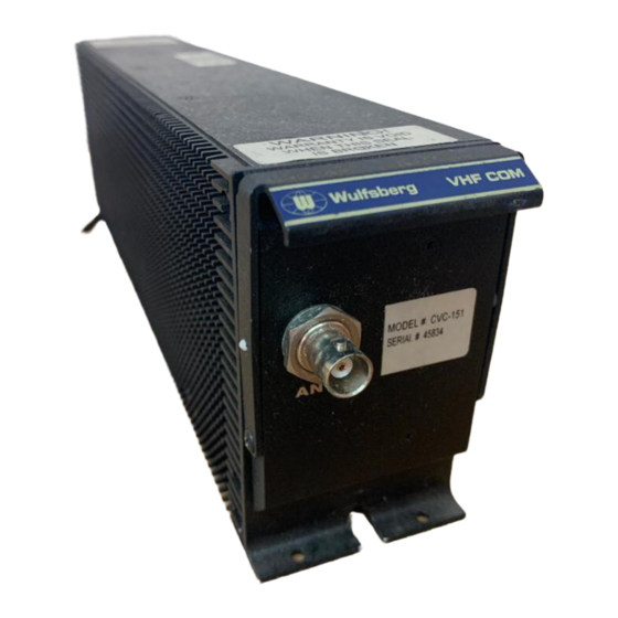
- Page 2 CVC-151 VHF Communication System Installation Manual Installation Manual Engineering and Production of FliteLine™ Components by Wulfsberg Electronics, A Cobham Avionics & Surveillance Group Company Wulfsberg Electronics CVC-151 FliteLine VHF Transceiver System Manual Number 150-048100 Revision M COBHAM PRIVATE Page 2 150-048100 Rev.
- Page 3 Wulfsberg Electronics makes no warranty with regard to the documentation or data contained herein. Wulfsberg Electronics is not liable in the event of incidental, special, consequential, or any other damages in connection with or arising from furnishing, performance, or use of this manual.
- Page 4 CVC-151 VHF Communication System Installation Manual Record of Revisions Date Date Date Inserted Date Inserted 12/15/2005 01/12/2006 09/08/2006 03/29/2007 08/22/2007 04/21/2009 09/10/2009 03/06/2013 02/16/2017 05/10/2017 11/16/2017 03/28/2018 COBHAM PRIVATE Page 4 150-048100 Rev. M These commodities, technology or software are controlled in accordance with the United States Export Administration Regulations, Export Classification Control Number(ECCN) EAR99.
-
Page 5: Table Of Contents
CVC-151 VHF Communication System Installation Manual Table of Content Section Page SECTION 1 – GENERAL INFORMATION 1.1 Introduction ............................7 1.2 Applicability ............................7 1.3 Equipment Description ......................... 7 CVC-151 VHF Communications Transceiver ................7 CVC-152 Control Display Unit ....................7 1.4 Available Configuration Variations ...................... - Page 6 CVC-151 VHF Communication System Installation Manual Table of Content 2.4 Post-Installation Check ........................35 System Test ..........................35 2.5 Flight Check ............................36 SECTION 3 – OPERATION 3.1 General .............................. 37 LIST OF TABLES 1-1 CVC-151 Configuration Variations......................8 1-2 CVC-151 Specifications ........................12 1-3 ARINC 429 Received Labels ......................
-
Page 7: Section 1 - General Information
CVC-151 VHF Communication System Installation Manual Section 1 - General Information SECTION 1 – GENERAL INFORMATION NTRODUCTION This section contains information relative to the physical, mechanical, and electrical characteristics of the Wulfsberg CVC-151 VHF Communications System. PPLICABILITY This manual is applicable to all CVC-151 FliteLine VHF Communication Receivers built at the Prescott, Arizona facility. -
Page 8: Available Configuration Variations
CVC-151 VHF Communication System Installation Manual Section 1 - General Information VAILABLE ONFIGURATION ARIATIONS The CVC-151 is designed to be plug compatible with most older VC-401B installations. To accommodate the smaller size and weight of the CVC-151, versions are available with a ballast and/or adapter bracket to fit the large rack of the VC-401B and match the VC-401B weight as required. - Page 9 CVC-151 VHF Communication System Installation Manual Section 1 - General Information Table 1-1. CVC-151 Configuration Variations (Continued) HARDWARE Frequency Audio & Enhanced Tuning VARIATION (YY) Range Side tone HIRF With With Side CVC-151 Part 136.975 151.975 8.33 25.0 Requires Adapter Ballast Tone Number...
- Page 10 CVC-151 VHF Communication System Installation Manual Section 1 - General Information Table 1-1. CVC-151 Configuration Variations (Continued) HARDWARE Frequency Audio & Enhanced Tuning VARIATION (YY) Range Side tone HIRF With With Side CVC-151 Part 136.975 151.975 8.33 25.0 Requires Adapter Ballast Tone Number...
- Page 11 CVC-151 VHF Communication System Installation Manual Section 1 - General Information Table 1-1. CVC-151 Configuration Variations (Continued) HARDWARE Enhanced Frequency Range Audio & Side tone Tuning VARIATION (YY) HIRF With With Side CVC-151 Part 136.975 151.975 8.33 25.0 Requires Adapter Ballast Tone Number...
-
Page 12: Technical Specifications
CVC-151 VHF Communication System Installation Manual Section 1 - General Information ECHNICAL PECIFICATIONS Table 1-2 CVC-151 Specifications CERTIFICATION: Transmitter TSO-C169, DO-186A Class 3 & 5, and EUROCAE ED-23B, DO-160E ENV CAT. [(F2)Z]AAB[S(M)R(B)(B1)U(G)]EWXXXXZZAZCC[FY]H[A3E33]XXAX Receiver TSO-C169, DO-186A Class C & E, and EUROCAE ED-23B, DO-160E ENV. - Page 13 CVC-151 VHF Communication System Installation Manual Section 1 - General Information Table 1-2. CVC-151 Specifications (cont'd) CHANNEL SPACING: 8.33 kHz Fixed, 25 kHz Fixed, 8.33/25 kHz Switchable RF POWER OUTPUT: 20 Watts nominal, 16 Watts minimum over temperature DUTY CYCLE: 1 min on 4 min off, continuous at reduced power without damage to unit.
-
Page 14: Recognized Arinc 429 Vhf Tuning Commands And Formats
CVC-151 VHF Communication System Installation Manual Section 1 - General Information ARINC 429 VHF T ECOGNIZED UNING OMMANDS AND ORMATS The CVC-151 has two ARINC 429 receive buses and one ARINC 429 transmit bus. Data received on either of the ARINC input channels will tune the radio. -
Page 15: Installation Kits And Accessories
CVC-151 VHF Communication System Installation Manual Section 1 - General Information NSTALLATION ITS AND CCESSORIES CVC-151 C ONNECTOR Installation of a CVC-151 requires a connector kit, P/N 050-02398-0000. The contents of the kit are as follows: Table 1-7. Part list, CVC-151 Connector Kit (050-02398-0000, Rev F) INGLE OUNTING When installing a single system, use P/N 400-048124-01 (Single Mounting Tray, Non-Safety Wire... -
Page 16: Recommended Antennas
CVC-151 VHF Communication System Installation Manual Section 1 - General Information ECOMMENDED NTENNAS The following is list of recommended Wulfsberg antennas for the CVC-151. The installer is responsible for determining if these antennas are appropriate for the given installation. Table 1-8 CVC-151 Recommended Antennas Part number Frequency Range Maximum Aircraft Speed... -
Page 17: Fcc Compliance
CVC-151 VHF Communication System Installation Manual Section 1 - General Information 1.14 FCC Compliance This device complies with part 15 of the FCC Rules. Operation is subject to the following two conditions: (1) This device may not cause harmful interference, and (2) this device must accept any interference received, including interference that may cause undesired operation. -
Page 18: Section 2 - Installation
CVC-151 VHF Communication System Installation Manual Section 2 – Installation SECTION 2 – INSTALLATION 2.1 General This section contains suggestions and factors to consider before installing the CVC-151. Close adherence to these suggestions will assure a more satisfactory performance from the equipment. Unpacking and Inspecting Equipment Exercise care when unpacking the equipment. -
Page 19: Dual Installation Considerations
CVC-151 VHF Communication System Installation Manual Section 2 – Installation C. Dual Installation Considerations (1) Reduction of cross radio interference by using Transmit Interlock feature. All radio transceivers have a noise floor associated with the transmitted output signal. When two or more radios are installed on the same aircraft, the transmitted noise floor can cause the squelch of a radio operating in receive to open if care is not taken to maximize the isolation between the antennas of the two systems. -
Page 20: Three Radio System Transmit Interlock Wiring 1
CVC-151 VHF Communication System Installation Manual Section 2 – Installation Figure 2-1 Three Radio System Transmit Interlock Wiring 1 COBHAM PRIVATE Page 20 150-048100 Rev. M These commodities, technology or software are controlled in accordance with the United States Export Administration Regulations, Export Classification Control Number(ECCN) EAR99. -
Page 21: Cvc-151 Single Mounting Tray Installation (Sheet 1 Of 3) (Dwg. No. 154-048100, Rev. F)
CVC-151 VHF Communication System Installation Manual Section 2 – Installation Figure 2-2. CVC-151 Single Mounting Tray Installation (Sheet 1 of 3) (Dwg. No. 154-048100, Rev. F) COBHAM PRIVATE Page 21 150-048100 Rev. M These commodities, technology or software are controlled in accordance with the United States Export Administration Regulations, Export Classification Control Number(ECCN) EAR99. - Page 22 CVC-151 VHF Communication System Installation Manual Section 2 – Installation Figure 2-2. CVC-151 Single Mounting Tray Installation (Sheet 2 of 3) (Dwg. No. 154-048100, Rev. F) COBHAM PRIVATE Page 22 150-048100 Rev. M These commodities, technology or software are controlled in accordance with the United States Export Administration Regulations, Export Classification Control Number(ECCN) EAR99.
- Page 23 CVC-151 VHF Communication System Installation Manual Section 2 – Installation Figure 2-2. CVC-151 Single Mounting Tray Installation (Sheet 3 of 3) (Dwg. No. 154-048100, Rev. F) COBHAM PRIVATE Page 23 150-048100 Rev. M These commodities, technology or software are controlled in accordance with the United States Export Administration Regulations, Export Classification Control Number(ECCN) EAR99.
-
Page 24: Envelope Drawing, Mounting Tray, 4 Inch (Sheet 1 Of 2) (Dwg. No. 154-04047 Rev. D)
CVC-151 VHF Communication System Installation Manual Section 2 – Installation Figure 2-3. Envelope Drawing, Mounting Tray, 4 Inch (Sheet 1 of 2) (Dwg. No. 154-04047, Rev. D) COBHAM PRIVATE Page 24 150-048100 Rev. M These commodities, technology or software are controlled in accordance with the United States Export Administration Regulations, Export Classification Control Number(ECCN) EAR99. - Page 25 CVC-151 VHF Communication System Installation Manual Section 2 – Installation Figure 2-3. Envelope Drawing, Mounting Tray, 4 Inch (Sheet 2 of 2) (Dwg. No. 154-04047, Rev. D) COBHAM PRIVATE Page 25 150-048100 Rev. M These commodities, technology or software are controlled in accordance with the United States Export Administration Regulations, Export Classification Control Number(ECCN) EAR99.
-
Page 26: Interconnect Wiring Diagram, Cvc-151 To Cvc-152 (Sheet 1 Of 1)
CVC-151 VHF Communication System Installation Manual Section 2 – Installation Figure 2-4. Interconnect Wiring Diagram, CVC-151 TO CVC-152 (Sheet 1 of 1) (Dwg. No. 152-248130, Rev E) COBHAM PRIVATE Page 26 150-048100 Rev. M These commodities, technology or software are controlled in accordance with the United States Export Administration Regulations, Export Classification Control Number(ECCN) EAR99. -
Page 27: Interconnect Wiring Diagram, Cvc-151 And Cvn-251 To Ccn-955 (Sheet 1 Of 1)
CVC-151 VHF Communication System Installation Manual Section 2 – Installation Figure 2-5. Interconnect Wiring Diagram, CVC-151 AND CVN-251 TO CCN-955 (Sheet 1 of 1) (Dwg. No. 152-248150, Rev G) COBHAM PRIVATE Page 27 150-048100 Rev. M These commodities, technology or software are controlled in accordance with the United States Export Administration Regulations, Export Classification Control Number(ECCN) EAR99. - Page 28 CVC-151 VHF Communication System Installation Manual Section 2 – Installation This page intentionally left blank. COBHAM PRIVATE Page 28 150-048100 Rev. M These commodities, technology or software are controlled in accordance with the United States Export Administration Regulations, Export Classification Control Number(ECCN) EAR99.
-
Page 29: Cvc-151 Harnesses And Connector Assembly
CVC-151 VHF Communication System Installation Manual Section 2 – Installation D. CVC-151 Harness and Connector Assembly (1) The installer will supply and fabricate all external cables. The connectors and hardware required are supplied in the Wulfsberg installation kits listed in Section 1. Figure 2-5 illustrates the specific aspects of constructing the RF connector and the wiring connector housing. -
Page 30: Cvc-151 Rack Mount Connector 1
CVC-151 VHF Communication System Installation Manual Section 2 – Installation Figure 2-7. CVC-151 Rack Mount Connector 1 COBHAM PRIVATE Page 30 150-048100 Rev. M These commodities, technology or software are controlled in accordance with the United States Export Administration Regulations, Export Classification Control Number(ECCN) EAR99. -
Page 31: Cvn-251 Pin-Outs
CVC-151 VHF Communication System Installation Manual Section 2 – Installation Table 2-1. CVC-151 Pin-outs DESCRIPTION DESCRIPTION D-DATA NOT USED +28V IN RESERVED +28V IN RESERVED NOT USED RESERVED POWER RETURN RESERVED NOT USED NOT USED POWER RETURN RESERVED NOT USED RESERVED RESERVED NOT USED... - Page 32 CVC-151 VHF Communication System Installation Manual Section 2 – Installation Table 2-1. CVC-151 Pin-outs (cont’d) DESCRIPTION DESCRIPTION NOT USED ENABLE COMM AUDIO OUT HI NOT USED NOT USED INTERLOCK RESERVED NOT USED NOT USED COMM AUDIO OUT LO ARINC IN 1B NOT USED GRAY CODE IN 1B ARINC OUT B (429)
-
Page 33: Cvc-151 Polarizing Post Assembly 1
CVC-151 VHF Communication System Installation Manual Section 2 – Installation Figure 2-8. CVC-151 Polarizing Post Assembly 1 COBHAM PRIVATE Page 33 150-048100 Rev. M These commodities, technology or software are controlled in accordance with the United States Export Administration Regulations, Export Classification Control Number(ECCN) EAR99. -
Page 34: Antenna Installation
CVC-151 VHF Communication System Installation Manual Section 2 – Installation (5) The Interconnect Wiring Diagram Figures 2-3 and 2-4 identifies those wires that must be shielded or twisted. (6) Connect the external wiring to the CVC-151 and associated equipment using the appropriate interconnect drawings. -
Page 35: Post-Installation Check
CVC-151 VHF Communication System Installation Manual Section 2 – Installation Table 2-2. Strapping Options Optional Function Strap (CVC-151) Active Frequency Tuning P1001-71 to ground System Number “1” P1001-54 to ground System Number “2” P1001-95 to ground System Number “3” P1001-95 and P1001-54 ungrounded Remote Transfer Function P1001-56 to one terminal of a momentary SPST (Panel or Yoke Mounted) -
Page 36: Flight Check
CVC-151 VHF Communication System Installation Manual Section 2 – Installation Flight Check A flight test is recommended after the installation is completed to ensure satisfactory performance of the equipment in its normal environment. Check all aircraft control movements to be sure no electrical cables interfere with their operation. To check the communications transceiver, maintain an appropriate altitude and contact a ground station facility at a range of at least fifty nautical miles. -
Page 37: Section 3- Operation
CVC-151 VHF Communication System Installation Manual Section 3– Operation 3.1 General Refer to Pilot's Guide, Avionics Systems, FliteLine, Publication No. 150-047012. COBHAM PRIVATE Page 37 150-048100 Rev. M These commodities, technology or software are controlled in accordance with the United States Export Administration Regulations, Export Classification Control Number(ECCN) EAR99.
Need help?
Do you have a question about the COBHAM FliteLine CVC-151 and is the answer not in the manual?
Questions and answers