Table of Contents
Advertisement
Advertisement
Table of Contents

Related Manuals for Turf Equipment Z-SPRAY


Summary of Contents for Turf Equipment Z-SPRAY
- Page 1 Z-SPRAY ® For Serial Nos. 406,294,345 & Higher Part No. 4504-922 Rev. A...
- Page 2 (or torque) on this class of machine will be y lower. ©2020 Z Turf Equipment is part of the Exmark® family of Contact us at www.zturfequipment.com. products Printed in the USA 415 Industrial Row...
-
Page 3: Introduction
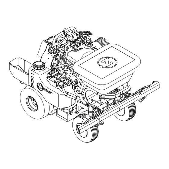
BEFORE OPERATING YOUR Z-SPRAY, CAREFULLY READ THIS MANUAL IN ITS ENTIRETY. By following the operating, maintenance, and safety instructions, you will prolong the life of your Z-Spray, g313833 Figure 1 maintain its maximum efficiency, and promote safe operation. 1. Model and serial number location... -
Page 4: Table Of Contents
Contents Motion Control Tracking Adjustment .....54 Cleaning ............55 Clean Engine and Exhaust System Introduction ............3 Area ............55 Safety ..............5 Remove Engine Shrouds and Clean Safety Alert Symbol ......... 5 Cooling Fins..........55 General Safety ..........5 Clean Debris From Machine ......55 Safety and Instructional Decals ....... -
Page 5: Safety
General Safety This machine is capable of amputating hands and The intended use of the spreader-sprayer is for lawn feet and of throwing objects. Z Turf Equipment care. designed and tested this machine to offer reasonably safe service; however, failure to comply with safety Safety Alert Symbol instructions may result in injury or death. -
Page 6: Safety And Instructional Decals
• Keep all safety signs legible. Remove all grease, • New safety signs may be obtained from dirt and debris from safety signs and instructional your authorized Z Turf Equipment dealer or labels. distributor. • Replace all worn, damaged, or missing safety •... - Page 7 Safety decal135-6430 135-6430 1. Press and hold the foot 2. Release the foot pedal to pedal to lock the caster unlock the caster wheels wheels in the straight to allow turning. position. decal142-3351 142-3351 1. Spread On-Pull handle 5. Spread Lock-Rotate counterclockwise to unlock;...
- Page 8 Safety decal135-6285 135-6285 1. Water pressure—decrease 5. Center nozzle spray—off 2. Water pressure—increase 6. Center nozzle spray—on 3. Left nozzle spray—off 7. Right nozzle spray—off 4. Left nozzle spray—on 8. Right nozzle spray—on decal135-6420 135-6420...
- Page 9 Safety decal142-3911 142-3911 1. Read the instructions before servicing or performing 5. Check tire and caster wheel pressure (4 locations) maintenance 2. Time interval 6. Grease idler pivot; refer to the Operator's manual for further instructions 3. Check engine oil level 7.
- Page 10 Safety decal135-6223 135-6223 1. Fast 15. Spreader speed 2. Slow 16. Spreader speed—increase 3. Neutral 17. Spreader speed—decrease 4. Reverse 18. Spray pump—On 5. Warning—Read the Operator’s Manual. Do Not operate 19. Spray pump—Off this machine unless you are trained. Wear hearing protection 6.
- Page 11 Safety 142-3313 Spreader / Sprayer Calibration: Mixing of liquid or dry product should be in accordance to manufacturers labels. Remember this is designed for low volume spraying so the mix will be more concentrated. Remember that your machine is factory set to put down 1/3 gallon of liquid per 1,000 sq. ft ( at 5MPH and _______ SPACING________ CAPACITY CAPACITY...
-
Page 12: Specifications
Specifications Specifications • Fuses: – 10 amp main fuse Systems – 30 amp sprayer fuse – 1 amp speedometer fuse Engine Safety Interlock System • Engine Specifications: See your Engine Owner’s Manual Engine will not start unless the interlock key is installed in the OPC switch. -
Page 13: Dimensions
Specifications Tires & Wheels – Only One Boom: 2 ft (0.6 m) • Spray Pump: Remco 5500 Series Diaphragm Drive Pump-12VDC Pneumatic (Air-Filled) Spray Nozzles 46 & 52 Quantity Hypro Air Injected Tips-Ceramic Tread K358 K500 Tip Color Pressure Gallons/ 1,000 Size 20 x 8.00–8 20 x 10.50–8... -
Page 14: Torque Requirements
Specifications Torque Requirements Curb Weight: 52 Inch Model 52 Inch XL Bolt Location Torque Model Wheel Hub 235 ft-lb (319 N-m) Dry Weight 950 lb (431 kg) 960 lb (435 kg) Crankshaft Bolt 35 ft-lb (47 N-m) Only Hopper 1170 lb (531 kg) 1180 lb (535 kg) Engine Mounting Bolts 132 in-lb (15 N-m) -
Page 15: Product Overview
Operation Product Overview Operation Note: Determine the left and right sides of the machine from the normal operating position. Controls Become familiar with all the controls before starting the engine and operating the machine. Motion Control Levers The motion control levers, located on each side of the top console, control the forward and reverse motion of the machine. - Page 16 Operation Choke Control To disengage the brake, push the lever back and down. Located in the center of the control console (see Figure 5). When parking on a steep slope, the wheels must be chocked or blocked in addition to the brake being The choke is used to aid in starting a cold engine.
- Page 17 Operation Spray System Switch The hour meter is connected to a charge circuit installed in the engine block and it records the Located to the left of the ignition switch. number of hours that the engine has run. If ignition switch is left on without engine running, hour meter Push on the top of the switch to turn on the spray system pump as well as the spot spray foot switch...
- Page 18 Operation Push the lever forward to turn on the center nozzle Opening the valve allows liquid to the hose reel for spray. Pull the lever rearward to turn it off. spraying out of the hand spray wand. When hose reel is not in use, be sure to turn valve off to prevent boom tips from dripping.
- Page 19 Operation g271205 Figure 11 g027373 Transferring product from right tank to left Figure 12 1. Fence 3. Side deflector lowered 2. Flowers Spread On/Off Located on the right side of the control tower and is Rate Gate Dial and Linkage the top cable (see Figure 7) Located at the front of the machine below the Pull the handle up to turn on the spreader impeller.
-
Page 20: Caster Wheel Lock Foot Pedal
• Evaluate the terrain to determine what accessories and attachments are needed to properly and safely perform the job. Only use accessories and attachments approved by Z Turf Equipment. • Inspect the area where the equipment is to be used and remove all rocks, toys, sticks, wires,... -
Page 21: Pre-Start
Operation Chemical Safety Not exceed recommended system application pressure. WARNING • Handle chemicals in a well ventilated area. Chemical substances used in the spreader-sprayer • Have clean water available especially when filling system may be hazardous and toxic to you, the spray tank. - Page 22 Operation DANGER DANGER In certain conditions gasoline is extremely In certain conditions during fueling, static flammable and vapors are explosive. electricity can be released causing a spark which can ignite gasoline vapors. A fire or explosion A fire or explosion from gasoline can burn you, from gasoline can burn you and others and cause others, and cause property damage.
-
Page 23: Operating Instructions
Operation flame or any enclosed area where open pilot lights • The owner/user can prevent and is responsible or heat appliances are present. for accidents or injuries occurring to himself or herself, other people or property. Operating Instructions • This machine was designed for one operator only. Do not carry passengers and keep all others away from machine during operation. - Page 24 Operation changing directions. Do Not spread/spray in • Reduce the weight of the load when operating reverse unless absolutely necessary. on hills and rough terrain to avoid tipping or overturning of the machine. • Stop spreading/spraying when making tight turns to minimize uneven distribution pattern, •...
- Page 25 Operation machine could suddenly roll over if a wheel goes WARNING over the edge or the edge collapses. Keep a safe Spray wand traps liquids under high pressure, distance (twice the width of the machine) between even when engine is off. High pressure spray the machine and any hazard.
- Page 26 Operation the machine and cause a loss of control. Follow directions for counter weights. • If you lose control of the machine, step off and away from the direction of travel of the machine. Starting the Engine Ensure the motion control lever is in the neutral position.
-
Page 27: Operating The Sprayer
Operation The machine will move faster the farther the motion control lever is moved from the neutral position. To stop, position both motion control levers in the neutral position; releasing the lever will automatically return it to neutral. Note: Stopping distance may vary depending on the spreader-sprayer load. - Page 28 Operation chemicals in the spray tank at night and then spray Set the spray pump switch to the “ON” position. in the morning. This would lead to separation of the chemicals and possible damage to the sprayer components. Note: Clean your sprayer thoroughly after all applications.
-
Page 29: Using The Sprayer Tank Shutoff Valves
Operation g311514 Figure 23 1. Left tank return valve 3. Right tank suction valve (open position) (close position) g312788 Figure 21 4. Right tank return valve 2. Left tank suction valve (close position) (open position) 1. Outer spray boom Selecting Both Spray Tanks Using the Sprayer Tank Shutoff Valves Rotate the valve handles as shown in Figure 24. - Page 30 Operation To use the spray wand: WARNING Spray wand traps liquids under high pressure, even when engine is off. High pressure spray discharge could cause serious injury or death. • Keep clear of nozzle and Do Not direct spray or stream at people, pets, or non-work area property.
- Page 31 Operation Return the wand back to its holder. Return the wand to its holder. Set the spray control levers to the “OFF” position, Important: Contact an Authorized Service disengage the pump, and stop the engine. Dealer if the spreader-sprayer fails to operate properly.
-
Page 32: Operating The Spreader
Operation Note: Clean your spreader thoroughly after all The lavender colored air injected tips come standard on the machine. These tips will apply liquid material applications. at .34 (1/3) gallons per 1,000 sq. ft. at 5 mph and 40 psi. Each tip has a 5-psi shut-off screen to prevent Before Operating the Spreader drip. - Page 33 Operation Note: Make sure the machine has been calibrated properly before starting the spreading application. Start the engine and place the throttle midway between the “SLOW” and “FAST” positions. Set the impeller speed to appropriate broadcast rate setting and turn on the spray system switch. Move the throttle to the “FAST”...
-
Page 34: Spreader Calibration
Operation Determining the Distribution Pattern Operator supplied equipment: 15 shallow collection pans and 15 graduated measuring cylinders The most accurate method to measure the distribution is to use shallow collection pans and graduated measuring cylinders. In the example below, 15 shallow collection pans approximately 30 cm (12 inches) wide, 91 cm (36 inches) long, and 5 cm (2 inches) tall are used. - Page 35 Operation To adjust the spreader pattern, refer to the Spreader Pattern Adjustment section. Repeat steps 5 through 11 until an uniform pattern is achieved. Determining the Effective Spreading Width The effective width is used to determine the uniform distribution of the material. Note: The spreading width range is 3 ft (0.9 m) up to 25 ft (7.6 m).
- Page 36 Operation starting marker to ensure the spreader is at full speed when crossing the first mark of the course. Set the appropriate gate dial setting (reference the Spreading Charts section as a starting point). Add material to the hopper (for example, 25 lb (11.3 kg) was added).
- Page 37 Operation g314272 Figure 33 1. Spreader pattern control 4. Start notch if pattern is heavy to right side 2. Rotate counterclockwise 5. Rotate clockwise to lock to unlock 3. Start notch if pattern is heavy to left side Lock the spreader pattern control by turning the handle clockwise 90 degrees.
- Page 38 Operation Spreading Charts Note: The Dial Settings chart and the Grass Seed Spreading chart are provided with permission from the Brinly-Hardy Company; reference the Brinly-Hardy Company website for more information. These charts are to be used as an approximate guideline only. Other factors, such as weather conditions, spreader operation, and condition of materials, will affect the results.
- Page 39 Operation The chart below is for reference only. When spraying and spreading at the same time, set the spread pattern to twice the width of the spray; this will help avoid striping and streaking. For example, standard spray width = 9 ft (2.7 m) and spread width = 18 ft (5.4 m).
-
Page 40: After Operation
Operation After Operation General Safety • Park machine on level ground and allow the machine to cool. Never allow untrained personnel to service machine. • Disengage the spray or close the spreader gate, set the parking brake, stop engine and remove key or g314318 disconnect spark plug wire. - Page 41 Operation Loading the Machine Use extreme caution when loading machines on trailers or trucks. One full width ramp that is wide enough to extend beyond the rear tires is recommended instead of individual ramps for each side of the machine. A full width ramp provides a surface to walk on behind the machine.
-
Page 42: Maintenance
While maintenance or adjustments are being to the original equipment or failure to use made, someone could start the engine. original Z Turf Equipment parts could lead Accidental starting of the engine could seriously to serious injury or death. Unauthorized injure you or other bystanders. -
Page 43: Recommended Maintenance Schedule(S)
Maintenance engine running. If the maintenance or adjustment CAUTION procedure require the engine to be running and Raising the machine for service or components moving, use extreme caution. maintenance relying solely on mechanical or hydraulic jacks could be dangerous. The WARNING mechanical or hydraulic jacks may not be Contact with moving parts or hot surfaces... -
Page 44: Periodic Maintenance
Maintenance Periodic Maintenance DANGER Charging or jump starting the battery may produce explosive gases. Battery gases can Check Engine Oil Level explode causing serious injury. Service Interval: Before each use or daily • Keep sparks, flames, or cigarettes away from battery. - Page 45 Maintenance short lengths to reduce voltage drop between Voltage Percent Maximum Charging systems. Make sure the cables are color coded or Reading Charge Charger Interval labeled for the correct polarity. Settings 12.6 or 100% 16 volts/7 CAUTION Charging greater amps Required Connecting the jumper cables incorrectly 12.4 –...
- Page 46 Maintenance g012785 Figure 36 1. Positive (+) cable on discharged battery 2. Positive (+) cable on booster battery 3. Negative (–) cable on the booster battery 4. Negative (–) cable on the engine block 5. Booster battery 6. Discharged battery 7.
-
Page 47: Check Safety Interlock System
Important: It is essential that the operator safety mechanisms be connected and in proper operating condition prior to use. Note: If the machine does not pass this test, do not operate. Contact your authorized Z Turf Equipment Service Dealer. Check the Normal Engine Starting Circuit... -
Page 48: Check For Loose Hardware
Maintenance Check for Loose Hardware Check Hydraulic Oil and Tank Level Service Interval: Before each use or daily Stop engine, wait for all moving parts to stop, and Service Interval: Every 40 hours remove key. Engage parking brake. Stop engine and wait for all moving parts to stop, Visually inspect machine for any loose hardware and remove key. -
Page 49: Check Tire Pressures
Maintenance Stop engine, wait for all moving parts to stop, and Changing oil unnecessarily could damage hydraulic remove key. Engage parking brake. system by introducing contaminates into the system. Carefully clean area around filter. It is important Hydraulic System Air Purge that no dirt or contamination enter hydraulic system. -
Page 50: Check Spreader System
Maintenance Check tire pressure in drive tires. Inflate all tires to 18 psi (124 kPa). Check Spreader System Service Interval: Every 50 hours Spray the hopper cables, accuway cable, and the deflector shield cable with silicone spray if needed. Clean the bottom of the hopper with a wire brush and clean off any fertilizer if needed. -
Page 51: Lubricate Grease Fittings
Maintenance Lubricate Grease Fittings Remove spark plugs, check condition and reset gaps, or replace with new plugs. See Engine Owner's Service Interval: Every 100 hours—Grease Manual. caster pivots (2x). Wheel Mount Screw Torque Every 100 hours—Grease idler pivot. Specification Note: See chart for service intervals. Service Interval: After the first 100 hours Stop engine, wait for all moving parts to stop, and Every 500 hours thereafter... - Page 52 Maintenance WHEN CHECKING THE ALTERNATOR If NO or LOW output is found check for bare COMPONENTS, PERFORM THE TEST IN THE wires or other defects. If shorted leads are not FOLLOWING SEQUENCE: visible, replace the stator. With the engine running at 3600 RPM output Temporarily disconnect stator wire harness from should be no less than 26 Volts.
-
Page 53: Adjustments
Maintenance Adjustments Note: Shut off engine, wait for all moving parts to stop, engage parking brake, and remove key before servicing, cleaning, or making any adjustments to the machine. Pump Drive Belt Tension Stop engine, wait for all moving parts to stop, and remove key. -
Page 54: Motion Control Linkage Adjustment
Maintenance Engage the park brake and check. If more adjustment is needed, repeat Step 6. Retighten the jam nuts. Check the park brake; repeat steps 5 through 6 if necessary. Motion Control Linkage Adjustment Park the machine on a level surface. Stop engine, wait for all moving parts to stop, and remove key. -
Page 55: Cleaning
Maintenance Cleaning To decrease the speed, turn the control linkage clockwise in quarter turn increments. Retighten the jam nuts on the control linkage. Clean Engine and Exhaust Drive the machine and check the full forward System Area tracking. Service Interval: Before each use or daily Replace the knee pad. -
Page 56: Waste Disposal
Maintenance Stop engine, wait for all moving parts to stop, and If a battery is being replaced or if the unit containing remove key. Engage parking brake. the battery is no longer operating and is being scrapped, take the battery to a local certified recycling Clean off any oil, debris, or build-up on the center. -
Page 57: Storage
Storage Storage Battery Storage Disconnect the battery and place on a trickle charger Extended or Winter Storage for a few hours once per month. To help protect the pumps from freezing temperatures make sure the unit is free of all caustic chemicals and residue. -
Page 58: Troubleshooting
Troubleshooting Troubleshooting Important: It is essential that all operator safety mechanisms be connected and in proper operating condition prior to use. When a problem occurs, do not overlook the simple causes. For example: starting problems could be caused by an empty fuel tank. The following table lists some of the common causes of trouble. - Page 59 Troubleshooting Problem Possible Cause Corrective Action Engine overheats 1. Engine load is excessive 1. Reduce the ground speed. 2. Oil level in the crankcase is low. 2. Add oil to the crankcase. 3. Cooling fins and air passages for the 3.
-
Page 60: Schematics
Schematics Schematics Electrical Schematic-XL Models g314373... - Page 61 Schematics Electrical Schematic-All Models Except XL g271692...
-
Page 62: Information
While the exposure from Z Turf Equipment products may be negligible or well within the “no significant risk” range, out of an abundance of caution, Z Turf Equipment has elected to provide the Prop 65 warnings. Moreover, if Z Turf Equipment does not provide these warnings, it could be... - Page 63 Service Record Date: Description of Work Done: Service Done By:...
- Page 64 Engine Serial No. (E/No) Serial No. Z Turf Equipment is part of the Exmark® family of products. © 2020 Exmark Mfg. Co., Inc. All Rights Reserved. Printed in the USA. 415 Industrial Row • Beatrice, NE 68310 • (402) 223-6375 • Fax (402) 223-5489...
Need help?
Do you have a question about the Z-SPRAY and is the answer not in the manual?
Questions and answers