
Related Manuals for Turf Equipment Z-SPRAY JUNIOR Series


Summary of Contents for Turf Equipment Z-SPRAY JUNIOR Series
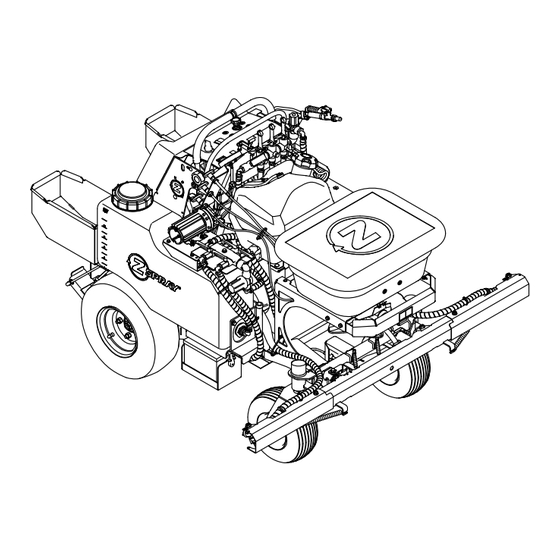
- Page 1 Z-SPRAY ® JUNIOR SERIES For Serial Nos. 411,294,212 & Higher Part No. 4505-818 Rev. A...
- Page 2 As configured to meet safety, emission, and operating requirements, the actual engine horsepower (or torque) on this class of machine will be significantly lower. ©2021 Z Turf Equipment is part of the Contact us at www.zturfequipment.com. Exmark® family of products Printed in the USA...
-
Page 3: Introduction
If additional information is needed, or should you require trained mechanic service, contact your authorized Z Turf Equipment dealer or distributor. All Z Turf Equipment dealers and distributors are kept informed of the latest service methods. Many are equipped to provide prompt and efficient service in the field or at their service stations. -
Page 4: Table Of Contents
Contents Cleaning ............52 Cleaning and Storing Safety......52 Clean Engine and Exhaust System Introduction ............3 Area ............52 Safety ..............5 Remove Engine Shrouds and Clean Safety Alert Symbol ......... 5 Cooling Fins..........52 General Safety ..........5 Clean Debris From Machine ......53 Safety and Instructional Decals ....... -
Page 5: Safety
Safety Safety General Safety This machine is capable of amputating hands and The intended use of the spreader-sprayer is for lawn feet and of throwing objects. Always follow all safety care. instructions to avoid serious personal injury or death. • Read, understand, and follow all instructions Safety Alert Symbol and warnings in the Operator’s Manual and on the machine, engine, and attachments. -
Page 6: Safety And Instructional Decals
• Keep all safety signs legible. Remove all grease, • New safety signs may be obtained from dirt and debris from safety signs and instructional your authorized Z Turf Equipment dealer or labels. distributor. • Replace all worn, damaged, or missing safety •... - Page 7 Safety decal135-6725 135-6725 1. Cutting/dismemberment hazard—stay away from moving parts. decal135-6430 135-6430 1. Press and hold the foot 2. Release the foot pedal to pedal to lock the caster unlock the caster wheels wheels in the straight to allow turning. position.
- Page 8 Safety decal135-7911 135-7911 1. Hydro oil level—Full 2. Hydro oil level—Add decal142-4365 142-4365 1. Spread On-Pull handle 5. Spread Lock-Rotate counterclockwise to unlock; rotate clockwise to lock. 2. Spread Off-Push handle 6. Deflector-Pull knob up to down open 3. Spread pattern 7.
- Page 9 Safety decal142-3919 142-3919 1. Read the instructions before servicing or performing 5. Check tire and caster wheel pressure (4 locations) maintenance 2. Time interval 6. Grease idler pivot; refer to the Operator's manual for further instructions 3. Check engine oil level 7.
- Page 10 Safety decal142-4183 142-4183 1. Fast 14. Park brake—Off 2. Slow 15. Spreader speed 3. Neutral 16. Spreader speed—Increase 4. Reverse 17. Spreader speed—Decrease 5. Warning—Read the Operator’s Manual; Do Not operate 18. Spray pump switch—On this machine unless you are trained. Wear hearing protection.
- Page 11 Safety decal142-4366 142-4366 1. Spray pressure—Decrease 5. Center nozzle spray—Off 2. Spray pressure—Increase 6. Center nozzle spray—On 3. Left nozzle spray—Off 7. Right nozzle spray—Off 4. Left nozzle spray—On 8. Right nozzle spray—On 142-4373 Spreader / Sprayer Calibration: Mixing of liquid or dry product should be in accordance to manufacturers labels. Remember this is designed for low volume spraying so the mix will be more concentrated.
-
Page 12: Specifications
Specifications Specifications • Fuses: – 10 amp main fuse Systems – 30 amp sprayer fuse – 1 amp speedometer fuse Engine Operator Controls • Engine Specifications: See your Engine Owner’s Manual Steering and Motion Control: • Engine Oil Type: Exmark 4–Cycle Premium •... -
Page 13: Dimensions
Specifications Tires & Wheels Spray Wand Nozzle Drive Adjustable flow rate and spray pattern. Pneumatic (Air-Filled) Spreader System Quantity • Maximum Hopper Capacity: 120 lb (54.4 kg) Tread K500 • Spreader Motor: Hydraulic motor Size 18 x 7.50–5 • Spreader Width: Adjustable from 3 ft (0.9 m) up Ply Rating to 25 ft (7.6 m). -
Page 14: Torque Requirements
Specifications Torque Requirements Curb Weight: Dry Weight 730 lb (331 kg) Bolt Location Torque Only Hopper Full 850 lb (386 kg) Wheel Hub 235 ft-lb (319 N-m) Only Sprayer Tanks Full 830 lb (376 kg) Crankshaft Bolt 35 ft-lb (47 N-m) Spray and Hopper Full 1050 lb (476 kg) Engine Mounting Bolts... -
Page 15: Product Overview
Operation Product Overview Operation Note: Determine the left and right sides of the machine from the normal operating position. Controls Become familiar with all the controls before starting the engine and operating the machine. Motion Control Levers The motion control levers, located on each side of the top console, control the forward and reverse motion of the machine. - Page 16 Operation put the choke in the “OFF” position. Do Not run a The hour meter is connected to a charge circuit warm engine with the choke in the “ON” position. installed in the engine block and it records the number of hours that the engine has run. If ignition switch is left on without engine running, hour meter will not run.
- Page 17 Operation engaged. The machine must be tied down and brake engaged when transporting. Spray System Switch Located to the left of the ignition switch. Push on the top of the switch to turn on the spray system pump as well as the spot spray foot switch on the left side of the foot pan.
- Page 18 Operation Push the lever forward to turn on the left nozzle spray. Pull the lever rearward to turn it off. Center Nozzle Spray Lever Located to the right of the left nozzle spray lever. Push the lever forward to turn on the center nozzle spray.
- Page 19 Operation Rate Dial and Linkage Spread On/Off Located on the right side of the control tower and is Located at the front of the machine below the the top cable (see Figure 6) spreader hopper. Pull the handle up to open the hopper gate. Push the The rate dial and linkage is used to set the amount of handle down to close the hopper gate.
-
Page 20: Before Operation
• Check that the following items are in place and in proper working condition: the operator presence controls, safety switches, guards, and shields. Do Not operate the machine unless they are in proper working condition. Replace worn or deteriorated parts with genuine Z Turf Equipment parts when necessary. - Page 21 Operation Chemical Safety • Handle chemicals in a well ventilated area. • Have clean water available especially when filling WARNING the spray tank. Chemical substances used in the spreader-sprayer • Do Not eat, drink, or smoke while working with system may be hazardous and toxic to you, chemicals.
-
Page 22: Operating Instructions
Operation machine or fuel container, or refuel, where CAUTION there is an open flame, spark, or pilot light Refueling engine is difficult especially when such as on a water heater or other appliance. using a larger refueling container (5 gal (19 L)). Operating Instructions When refueling, it is recommended to: •... - Page 23 Operation • Keep away from holes, ruts, bumps, rocks, and are often attracted to the machine and the other hidden hazards. Use care when approaching spreading/spraying activity. Never assume that blind corners, shrubs, trees, tall grass or other children will remain where you last saw them. objects that may hide obstacles or obscure vision.
- Page 24 Operation machine could suddenly roll over if a wheel goes WARNING over the edge or the edge collapses. Keep a safe Spray wand traps liquids under high pressure, distance (twice the width of the machine) between even when engine is off. High pressure spray the machine and any hazard.
- Page 25 Operation the machine and cause a loss of control. Follow directions for counter weights. • If you lose control of the machine, step off and away from the direction of travel of the machine. Starting the Engine Leave the motion control levers in neutral and engage the parking brake.
-
Page 26: Operating The Sprayer
Operation The machine will move faster the farther the motion control lever is moved from the neutral position. To stop, position both motion control levers in the neutral position; releasing the lever will automatically return it to neutral. Note: Stopping distance may vary depending on the spreader-sprayer load. - Page 27 Operation the sprayer. For example, Do Not mix and add Set the spray pump switch to the “ON” position. chemicals in the spray tank at night and then spray in the morning. This would lead to separation of the chemicals and possible damage to the sprayer components.
-
Page 28: Using The Sprayer Tank Shutoff Valves
Operation g315315 Figure 20 1. Left tank return valve 3. Right tank suction valve (close position) (open position) g312788 Figure 18 2. Left tank suction valve 4. Right tank return valve (close position) (open position) 1. Outer spray boom Selecting Both Spray Tanks Using the Sprayer Tank Rotate the valve handles as shown in Figure 21. - Page 29 Operation To use the spray wand: WARNING Spray wand traps liquids under high pressure, even when engine is off. High pressure spray discharge could cause serious injury or death. • Keep clear of nozzle and Do Not direct spray or stream at people, pets, or non-work area property.
- Page 30 Operation Return the wand back to its holder. Return the wand to its holder. Set the spray control levers to the “OFF” position, Important: Contact an Authorized Service disengage the pump, and stop the engine. Dealer if the spreader-sprayer fails to operate properly.
-
Page 31: Operating The Spreader
Operation Note: Clean your spreader thoroughly after all The lavender colored air injected tips come standard on the machine. These tips will apply liquid material applications. at .34 (1/3) gallons per 1,000 sq. ft. at 5 mph and 40 psi. Each tip has a 5-psi shut-off screen to prevent Before Operating the Spreader drip. - Page 32 Operation Note: Make sure the machine has been calibrated properly before starting the spreading application. Start the engine and place the throttle midway between the “SLOW” and “FAST” positions. Set the impeller speed to appropriate broadcast rate setting. Move the throttle to the “FAST” position and drive forward.
-
Page 33: Spreader Calibration
Operation The most accurate method to measure the distribution is to use shallow collection pans and graduated measuring cylinders. In the example below, 15 shallow collection pans approximately 30 cm (12 inches) wide, 91 cm (36 inches) long, and 5 cm (2 inches) tall are used. - Page 34 Operation To adjust the spreader pattern, refer to the Spreader Pattern Adjustment section. Repeat steps through until an uniform pattern is achieved. Determining the Effective Spreading Width The effective width is used to determine the uniform distribution of the material. g319658 Note: The spreading width range is 3 ft (0.9 m) up Figure 28...
- Page 35 Operation Measure and visibly mark the course length. Make sure to allow ample distance before the starting marker to ensure the spreader is at full speed when crossing the first mark of the course. Set the appropriate gate dial setting (reference the Spreading Charts section as a starting point).
- Page 36 Operation g317119 Figure 30 1. Spreader pattern control 4. Start notch if pattern is heavy to right side 2. Rotate counterclockwise 5. Rotate clockwise to lock to unlock 3. Start notch if pattern is heavy to left side Lock the spreader pattern control by turning the handle clockwise 90 degrees.
- Page 37 Operation Spreading Charts Note: The Dial Settings chart and the Grass Seed Spreading chart are provided with permission from the Brinly-Hardy Company; reference the Brinly-Hardy Company website for more information. These charts are to be used as an approximate guideline only. Other factors, such as weather conditions, spreader operation, and condition of materials, will affect the results.
- Page 38 Operation The chart below is for reference only. When spraying and spreading at the same time, set the spread pattern to twice the width of the spray; this will help avoid striping and streaking. For example, standard spray width = 9 ft (2.7 m) and spread width = 18 ft (5.4 m).
-
Page 39: After Operation
Operation After Operation General Safety • Park machine on level ground, disengage drives, set parking brake, stop engine, and remove key. Wait for all moving parts to stop before leaving the operator’s position. Allow the machine to cool before servicing, adjusting, fueling, unclogging, cleaning, or storing. - Page 40 Operation slope and the ramps extends up the slope. This will minimize the ramp angle. The trailer or truck should be as level as possible. Important: Do Not attempt to turn the machine while on the ramp, you may lose control and drive off the side.
-
Page 41: Maintenance
Unauthorized modifications to the original equipment or failure to use original Z Turf Equipment parts could lead to serious injury or death. Unauthorized changes to the machine, engine, fuel or venting system, may violate applicable safety... -
Page 42: Recommended Maintenance Schedule(S)
Maintenance Recommended Maintenance Schedule(s) Maintenance Service Maintenance Procedure Interval • Change the engine oil. After the first 5 hours • Change hydraulic system filter and fluid After the first 100 hours • Check the wheel hub slotted nut torque specification. •... -
Page 43: Periodic Maintenance
Maintenance Periodic Maintenance Note: To prevent damage due to freezing, battery should be fully charged before putting away for winter storage. Engine Maintenance Charge batteries in an open well ventilated area, Important: Refer to the Engine Owner’s Manual away from spark and flames. Unplug charger before for additional maintenance procedures. - Page 44 Maintenance Important: Make sure the negative battery cable Make sure the booster is a good and fully charged is disconnected and the battery charger used for lead acid battery at 12.6 volts or greater. Use charging the battery has an output of 16 volts and properly sized jumper cables (4 to 6 AWG) with 7 amps or less to avoid damaging the battery (see short lengths to reduce voltage drop between...
-
Page 45: Check For Loose Hardware
Maintenance Every 100 hours—Replace the dual element air cleaner element. Stop engine, wait for all moving parts to stop, and remove key. Engage parking brake. See the Engine Owner's Manual for maintenance instructions. Change Engine Oil g012785 Figure 32 Service Interval: After the first 5 hours 1. -
Page 46: Change Hydraulic System Filter And Fluid
Maintenance Turn filter clockwise until rubber seal contacts the filter adapter, then tighten the filter an additional 2/3 to 3/4 turn. Fill reservoir as stated in Check Hydraulic Oil and Tank Level. Hydro Oil Service Interval Exmark Premium Hydro After first 250 hours *Every 500 hours thereafter Mobil 1 15W-50... -
Page 47: Check Tire Pressures
Maintenance filter, are removed or any of the hydraulic lines are Clean the bottom of the hopper with a wire brush disconnected. and clean off any fertilizer if needed. Stop engine and wait for all moving parts to stop. Change out the hopper bottom bushing or the Raise the rear of the machine up onto jack stands impeller if needed. -
Page 48: Check Fuel Filter And Tank
Maintenance Check Fuel Filter and Tank Check Condition of Belt Service Interval: Before each use or daily Service Interval: Every 40 hours Stop engine, wait for all moving parts to stop, and Stop engine, wait for all moving parts to stop, and remove key. - Page 49 Maintenance g289588 Figure 35 Output Test WHEN CHECKING THE ALTERNATOR COMPONENTS, PERFORM THE TEST IN THE FOLLOWING SEQUENCE: Temporarily disconnect stator wire harness from g268086 Figure 36 regulator-rectifier. Insert RED test lead into VΩ receptacle in meter. If NO or LOW output is found check for bare Insert BLACK test lead into COM receptacle.
-
Page 50: Adjustments
Maintenance Adjustments The DC Shunt MUST be installed on the NEGATIVE (-) terminal of the battery, (Figure 37) Note: Shut off engine, wait for all moving parts to to avoid blowing the fuse in the meter when testing the output of the 20 amp system. All connections stop, engage parking brake, and remove key before must be clean and tight for correct readings. -
Page 51: Motion Control Linkage Adjustment
Maintenance To increase the brake force, turn the linkage counterclockwise 1–2 turns. Engage the park brake and check. If more adjustment is needed, repeat step . Retighten the jam nuts. Check the park brake; repeat steps through if necessary. Repeat steps through for right side brake. Motion Control Linkage Adjustment Park the machine on a level surface. -
Page 52: Cleaning
Maintenance Cleaning To decrease the speed, turn the control linkage clockwise in quarter turn increments. Retighten the jam nuts on the control linkage. Cleaning and Storing Safety Drive the machine and check the full forward • Park machine on level ground, disengage drives, tracking. -
Page 53: Clean Debris From Machine
Maintenance Battery Disposal Stop engine, wait for all moving parts to stop, and remove key. Engage parking brake. DANGER Remove cooling shrouds from engine and clean cooling fins. Also clean dust, dirt, and oil from Battery electrolyte contains sulfuric acid, which external surfaces of engine which can cause is poisonous and can cause severe burns. -
Page 54: Storage
Storage Storage Battery Storage Disconnect the battery and place on a trickle charger Extended or Winter Storage for a few hours once per month. To help protect the pumps from freezing temperatures make sure the unit is free of all caustic chemicals and residue. -
Page 55: Troubleshooting
Troubleshooting Troubleshooting Important: It is essential that all operator safety mechanisms be connected and in proper operating condition prior to use. When a problem occurs, do not overlook the simple causes. For example: starting problems could be caused by an empty fuel tank. The following table lists some of the common causes of trouble. - Page 56 Troubleshooting Problem Possible Cause Corrective Action Engine overheats 1. Engine load is excessive 1. Reduce the ground speed. 2. Oil level in the crankcase is low. 2. Add oil to the crankcase. 3. Cooling fins and air passages for the 3.
- Page 57 Troubleshooting Problem Possible Cause Corrective Action Spray wand does not work. 1. Tank is empty. 1. Fill tank. 2. Control valve in wrong position. 2. Place in “open” position. 3. Wand is clogged or damaged. 3. Clean, repair, or replace wand. 4.
-
Page 58: Schematics
Schematics Schematics Electrical Schematic g317196... -
Page 59: Information
While the exposure from Z Turf Equipment products may be negligible or well within the “no significant risk” range, out of an abundance of caution, Z Turf Equipment has elected to provide the Prop 65 warnings. Moreover, if Z Turf Equipment does not provide these warnings, it could be... - Page 60 Notes:...
- Page 61 Notes:...
- Page 62 Service Record Date: Description of Work Done: Service Done By:...
- Page 64 Model No. Engine Serial No. (E/No) Serial No. ©2021 Z Turf Equipment is part of the Exmark® family of products All Rights Reserved Printed in the USA 415 Industrial Row • Beatrice, NE 68310 • (402) 223-6375 • Fax (402) 223-5489 www.zturfequipment.com...
Need help?
Do you have a question about the Z-SPRAY JUNIOR Series and is the answer not in the manual?
Questions and answers