
Related Manuals for UNIFILLER UNIVERSAL 1000i sv

Summary of Contents for UNIFILLER UNIVERSAL 1000i sv
- Page 1 UNIVERSAL 1000i sv DEPOSITOR INSTRUCTIONS AND SPARE PARTS Manual Part # UVL1000i sv-Ins-UK 09/15/2015 Ver 8 From serial number U1V52098 Translation from the Original Instructions...
-
Page 2: Table Of Contents
TABLE OF CONTENTS SAFETY INSTRUCTIONS AND WARNINGS ..........................3 INTRODUCTION ................................... 6 CONTACTING UNIFILLER ..............................6 MACHINE DESCRIPTION ............................... 7 SERIAL NUMBER LOCATION ..............................8 POWER REQUIREMENTS ..............................9 ..................................9 EQUIREMENTS ASSEMBLY AND OPERATION ..............................9 ............................... 10 RIMING... -
Page 3: Safety Instructions And Warnings
Before use ensure that the locks on the wheels are engaged. For servicing or technical support please contact UNIFILLER directly or one of its authorized suppliers or dealers. Unifiller Systems recommends the use of approved personal protection equipment... - Page 4 Do not operate machine without the product • cylinder installed. If it becomes necessary to operate the machine without a product cylinder in place, caution must be observed that you do not place any body parts near the operating parts of the machine, or pinch points.
- Page 5 • During operation of the machine, do not remove the red pin as the hopper and product cylinder may fall off, if action occurs during mid cycle. • Use caution when starting the machine as it may operate and move parts to their “Home”...
-
Page 6: Introduction
Introduction Thank you for purchasing UNIFILLER Equipment. We are sure you will get years of trouble free use and excellent productivity from your new investment. Please take a few minutes to read this manual and familiarize yourself with the layout of the controls, and the set up and operating procedure. -
Page 7: Machine Description
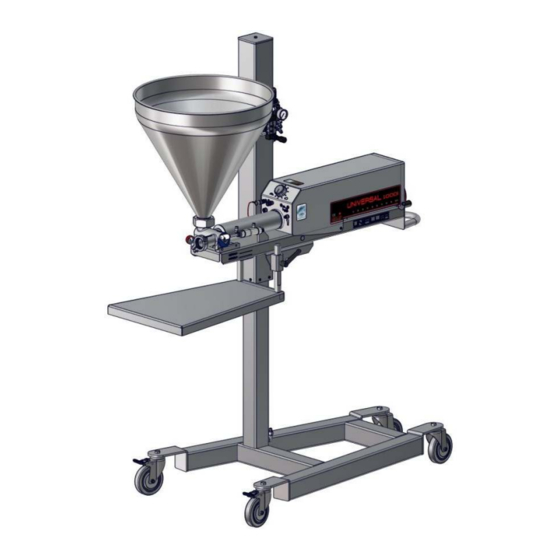
Machine description The Universal 1000i is an air operated positive displacement depositor. Intended uses Non intended uses Batter for cakes, muffins, etc Dry goods Fruit fillings Large chunks Icings, frostings and toppings Liquids Jams and jellies Stiff non settling products Creams, custards and mousse Anything that can be squeezed through a pastry bag... -
Page 8: Serial Number Location
Serial Number location Quote this number when ordering spare parts. It is located as shown. -
Page 9: Power Requirements
• It is recommended that the compressed air supplied to the depositor be run through an air dryer before connecting to the machine. Please contact Unifiller for details. • Use an airline with a minimum inside diameter of 3/8” (10mm) •... -
Page 10: Priming / Preparing To Deposit
Warning: To avoid possible tipping of the machine, keep the area under the work table clear. • To raise the machine, move and hold the black lever of the control valve in the up position (1). The machine will stop if the lever is released. •... -
Page 11: Deposit Volume Adjustment
Deposit Volume Adjustment • Press the foot pedal or trigger on the hand held nozzle once and 1 measured amount will be deposited. • For continuous deposits press and hold. • Run the machine 2 or 3 cycles, check the weight of the last deposit. -
Page 12: Purge Button
Purge Button A Purge Button (1) is located on the front base plate. This allows the depositor to be cycled manually without the need of a foot pedal or an external signal. This can be used to Prime the depositor, or cycle it during cleaning. -
Page 13: Disassembly For Sanitizing
Disassembly for Sanitizing General • Sanitizing requires that the machine must be disassembled. • Turn air off and remove supply line from machine. • Scrape down the inside of the hopper. • Reconnect supply line and turn air on. • Keep depositing until nothing more comes out of the outlet nozzle. •... - Page 14 • Remove Hopper and place top downwards on a sanitary surface. • Unclamp depositing attachment. • Remove the Safe-T-Valve block, by pulling the clevis off the pin, Swing Air cylinder away from block. • Pull the Safe-T-Valve out of the Safe-T-Valve block. •...
-
Page 15: Cleaning And Sanitizing
• Remove the product cylinder by sliding forward. • Remove the product piston. NOTE: • Use O-Ring tool to remove all O-Rings Cleaning and Sanitizing Cleaning Warnings - Abrasive materials may damage finish of this equipment. Use of the following types of cleaning agents is not acceptable and may cause damage to the machinery that the manufacturer cannot be held responsible for. -
Page 16: Sanitizing
Clean and sanitize the parts shown, and any attachment parts. Item Description Product Cylinder Product Cylinder O Ring Product Piston Product piston O Ring Safe-T-Valve Safe-T-Valve O Ring Clamp Clamp Gasket Safety Pin Safe-T-Valve Block Hopper Gasket Hopper • Mix 1 to 4 ounces (30-120ml) of Zep F.S. PROCESS CLEANER (green) per gallon (4ltr) of water. -
Page 17: Maintenance
Maintenance Turn air off, and remove supply line from machine before any maintenance is performed. IMPORTANT SAFETY NOTES: Any maintenance to the pneumatics system will require the top cover to be opened and pivoted up. Maintenance personnel will require a Phillips screwdriver to open the cover. -
Page 18: O Ring Care
O Ring Care The most important components of the machine are the O rings. These must be inspected and maintained daily. All O rings should be high quality Viton seal as supplied by Unifiller, or your authorized Unifiller dealer. Signs of wear include: Flatness, Abrasions, Cracks, and Cuts... -
Page 19: Preventative Maintenance
Preventative Maintenance Unifiller Systems distinguishes between two levels of care for equipment Machine Owner / Operator Care The operators of the machines are typically the “owners”, typically a person working with them. They depend on the machine to function reliably to be able to meet their production requirements. They most often know the machine best and can predict when something changes. -
Page 20: Spare Parts
Spare parts Product Cylinder Sizes To obtain the most accurate deposit volume, 4 different sizes of product cylinder and product piston are available. See chart following. To maintain portion accuracy, it is recommended that the % volume setting for the product piston be set between 12 to 80% of the scale, this will ensure optimum machine performance. -
Page 21: Parts Identification
Parts Identification It is highly recommended to carry a complete spare set of ‘O’ rings and seals, as these are vital to the accuracy of the machine. See O ring care section for a full list. Safe T Block... -
Page 22: Pneumatic Components 1
Pneumatic Components 1 Pneumatic Components 2... -
Page 23: Volume Adjustment
Volume Adjustment... -
Page 24: Front Pneumatic Components
Front Pneumatic Components... -
Page 25: Lower Frame
Lower Frame... -
Page 26: Upper Frame
Upper Frame Air Regulator - Filter 04876-00... -
Page 27: Depositing With Hot Product
Valve should be used. For products above 82° C/180° F and up to 95° C /203°F, an X hot product piston and Safe-T- Valve should be used. Contact Unifiller customer service for details. “HOT” versions of both parts are red in color... -
Page 28: Pneumatic Schematics
Pneumatic Schematics... - Page 29 Item Key Description Diagram Part number (May not look exactly as shown) Air Filter and Regulator Lever Valve 06207-00 Check Valve 00994-00 Rear 2 Way valve 01056-00 Front 2 Way valve 01056-00 Power Lift Height air 10069-00 cylinder 5 Way Valve 01882-00 Rear Flow control 01323-00...
- Page 30 Item Key Description Diagram Part number (May not look exactly as shown) Accessories Connection Foot Pedal signal connection Reset Button 21148-00 Safe T Valve Air 19009-00 cylinder...
-
Page 31: Trouble Shooting
Trouble Shooting Problem Cause Remedy Machine will Low air pressure. Check air supply for correct not cycle. operation. Also check pressure regulator setting 80 psi / 5.5 Bar. Pilot valves have loosened from Check pilot valves, ensure that they their mount bracket or are are secure. - Page 32 Problem Cause Remedy Machine Air quick connects are not secure. Check that all air connections are cycles but will securely attached. not deposit. Uni valve is inserted incorrectly. Remove clamp and align Uni valve with pin. Machine does Check front pilot valve. not finish cycle Machine stops in forward position.
-
Page 33: Piston Return Speed Control
Problem Cause Remedy Product Clamps are not tight. Check that all clamps are tight. leakage. Product piston or Uni valve O-rings Replace O-rings. are worn or damaged. Product Deposit speed set too fast. Decrease deposit speed. splashes. Machine Product stuck at neck of Hopper. Disconnect air, and remove Hopper Blockage safety pin. - Page 34 Der Hersteller: 7621 MacDonald Road, Delta, B.C, Canada, la Fabrication V4G 1N3 Name and address of the person authorised Unifiller Systems UK Ltd. to compile the technical file: Unit 6 Chieftain Business Center, Morris Name und Anschrift der Person, die Close bevollmächtigt, die technischen Unterlagen...
- Page 35 Sound Level Measurement All sound level readings taken at 1m from the front of the machine and 1.6m from the floor level. All readings are “A” weighted emission sound pressure level. Machine Sound level dB Compact Depositor 79.4 Uni1000i 75.2 Pro 1000i 75.2 Pro 2000...
Need help?
Do you have a question about the UNIVERSAL 1000i sv and is the answer not in the manual?
Questions and answers