Advertisement
Quick Links
Thank you for purchasing TF Model's product, please read all
instructions carefully before proceeding with the actual assembly.
Some steps are required to be done first, so please do a complete
dry fitting of all the parts before assembly.
Required items for finishing this product
1.
A comprehensive set of tools
2.
CA glue
3.
30 minute epoxy glue
4.
Trex 600 type mechanic, belt version
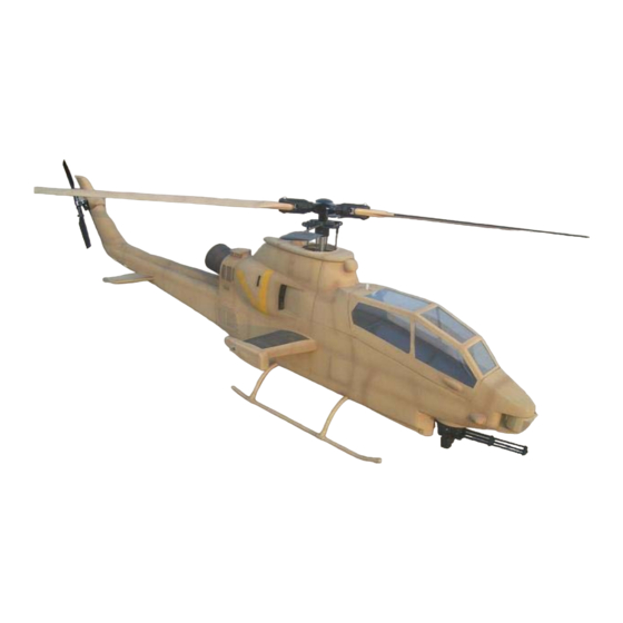
TF Model AH-1S 600
Advertisement

Related Manuals for TF Model COBRA AH-1S 600

Summary of Contents for TF Model COBRA AH-1S 600
- Page 1 TF Model AH-1S 600 Thank you for purchasing TF Model's product, please read all instructions carefully before proceeding with the actual assembly. Some steps are required to be done first, so please do a complete dry fitting of all the parts before assembly.
- Page 2 Recommended items for use in this product 1. TF Model 600 Slim tail gear box. Wood Formers Assembly 2.First glue the former F5 into the fuselage at 1.Locate all the wood formers for the main the tail joint location. Use photo for fuselage shown in the photo.
- Page 3 5.Another view of the formers F-4A and F-4B 6.Slide both landing gear cross memebers through the fuselage holes.Now centre the cross memember and tack glue in place with CA glue.Use the predrilled holes in the cross member as template and mark the 2 holes onto the shims, do both the front and back cross members.Drill 2mm diameter holes through to the outside of the fuselage.Secure...
- Page 4 9.Landing gear cross member screws. Screw from the outside in for a flush finish on the exterior. 10.Insert the landing gear plastic "T"s onto the cross members' ends and insert the landing skids through them. Once the landing gear is squared, tack glue the skids and cross members to the plastic "T".
- Page 5 13.The rudder servo mounting location viewed from the inside. THE FOLLOWING STEPS FOR TREX 600 VERSION ONLY 14.Locate the fuselage wing area doubler in the photo. 15.Next locate the wing stub outer reinforcement ring and glue it to the outside fuselage.
- Page 6 16.Now glue the wing area doubler to the inside of the main fuselage. Note the location of the reinforcement panel in the photo. The wing hole in the fuselage should sit inside the doubler hole on all sides.If the doubler interferes with the rear landing gear cross member,trim the doubler's corner until it fits.Do both sides of the fuselage insides.
- Page 7 20.Now join the front and rear fuselage halves 19.Photo shows the completed front and back using epoxy glue. Align the joint line mechanic shims. accurately before gluing. Wire Mesh Assembly 21.Cut the supplied wire mesh slightly larger than the openings circled in the photo and glue the mesh from the inside with epoxy.
- Page 8 Installing the Mechanic Once all the shims and mechanic mounting holes are done, install the mechanic into the fuselage.Due to the scale proportion of the Cobra, the fuselage is slim to scale and when installing the mechanic you need to carefully spread the sides of the fuselage in order to allow the mechanic to slip into the fuselage.
- Page 9 24.Install the bearing for the tension wheel and insert the tension wheel into the bearing. Also glue in the rear wood cross members at this time.Use epoxy glue for this. 25.Glue the other side frame onto the cross members and glue on the elbow gear box base.
- Page 10 28.Temporarily insert the supplied tail tube against the rear cross member and use it as a 29.Photo shows the completed assembly jig for gluing the front cross memebers. Tacky before inserting into the fuselage tail. glue the front cross members in place, remove the tail tube, then glue with epoxy.
- Page 11 32.Remove the pulley wheel bracket and remove the pulley from the elbow gear box assembly base board. Pull the timing belt through, note the direction of the belt. Install the pulley wheel through the belt and back into the base board,and reinstall the pulley wheel brackets and screw them in place.Pull the belt through the vertical tail tube.
- Page 12 34.After completing the above step, you can now glue the tail tiube to the elbow gear box wood frame using epoxy. Now install 2 ball links to the bell crank in the photo and connect the push rod forwards to the rudder servo and backwards, up along the vertical tail tube to the rudder pitch bell crank at the tail gear box.
- Page 13 35.We recommend that you glue a push rod support at the location indicated. 36.Connect the push rod to the rudder servo. Before connecting please power up the receiver and transmitter and centre the rudder servo. 37.After checking that the bell crank and rudder is operating smoothly and correctly, fit the tail cover on and drill 1 mm diameter holes for the fixing screws on both sides.
- Page 14 Now locate the tail rotor cover and trim it to fit the tail rotor location as in the following group of photos. Once the fitting is correct, glue into place. Front Cross Member Former Assembly 38.After installing the mechanics inside the fuselage, dry fit formers F2 in front of the front landing gear making sure that it does not interfere with the mechanic and anchillary...
- Page 15 39.Locate cross brace former F7 and the fuselage stays anchors. Use bolts and nuts to attach the cross brace to formers F2. 40.Carefully study the installation of the cross brace and the mounting of the fuselage stays in the photo, using it as reference. 41.Now proceed to gluing the battery tray to the floor on the front part of the fuselage in front of formers F2.
- Page 16 Upper Front Cover Assembly Fit the upper front cover onto the main fuselage and use clamps to achieve a flush fit on all sides. Once flush fit is achieved mark and drill 4 fixing holes on both inside lips. Glue 4 pegs on the upper front cover and fit in on to the upper main fuselage.
- Page 17 44.Use screws to fix the 2 parts. Canopy and Cockpit Assembly Glue the supplied canopy lock on the rear inside of the canopy frame. Dry fit the clear windows onto the canopy frame and glue them on the inside using silicone glue or canopy glue. Tack glue the cockpit support frame to the inside of the canopy frame first, fit the canopy frame onto the fuselage and check for a flush fit.
- Page 18 45.Glue in canopy lock. Remember to centre 46.Cockpit support frame. 47.View of cockpit support frame side.
- Page 19 48.Cockpit support frame and cockpit fitting. 49.Cockpit cut out for canopy lock. 50.Front canopy frame wood former and fixingtongue.
- Page 20 51.You might need to glue a wood shim indicated in the photo for the canopy lock to work properly. 52.Canopy lock once assembled correctly. 53.Completed canopy.
-
Page 21: Final Assembly
Final Assembly 54.Use the louvred cover and drill 4 holes at 4 corners and use screw to fix the cover on at the rudder location. This cover will become the rudder servo access hatch. 55.Refer to the separate instructions on assembling the XM-197 chain gun. - Page 22 57.Glue on the front optical sight at the location shown in the photo. Please note the wider diameter of the sight unit is the top. 58.Locate the rocket pods, Tow launchers and associated parts in the photo. 59.Glue the rocket pod face into both ends of the rocket tube.
- Page 23 60.Locate the rocket pod pylon and the wood hangers. 61.Insert and glue the rocket pod hangers into the underside of the rocket pod pylon. Do this for both pylons. Now glue the rocket pods onto the pylon hangers.Centre the rocket pods before gluing.Refer to the following photos for better info on gluing.
- Page 24 63.Note the orientation of the rocket holes when gluing. You can now glue the weapons onto the stub wing using the following group of photos for reference. The Tow launcher comes already assembled and you need to trim a rectangular hole on the underside of the wing at the tip to glue it on.After completing the weapons, glue the wings onto the fuselage and the wood reinforcement ring.
- Page 25 66.Front view of the wing weapons. Remove the rotor head and the swashplate by disconnecting the servo to swashplate ball links. Fit the top cover on the fuselage and decide on the method of fixing the top cover. Refer to the following group of photos for a better understanding and reference.
- Page 26 67.Remove the rotorhead and swahpplate and 68.You can choose to fix the top cover using dry fit the top cover on the fuselage. pegs and magnets as in the photo. 69.We recommend that you cut the top cover in half and glue the top cover separately to the 70.Fit the top cover on and refit the rotor head front upper cover and the main fuselage and swashplate assembly onto the main shaft.
Need help?
Do you have a question about the COBRA AH-1S 600 and is the answer not in the manual?
Questions and answers