Advertisement
Quick Links
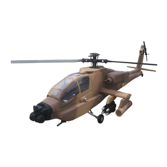
TF Model Apache 600 Manual
Thank you for purchasing TF Model's product, please read all instructions
carefully before proceeding with the actual assembly. Some steps are
required to be done first, so please do a complete dry fitting of all the
parts before assembly.
Required items for finishing this product
1. Sullivan Flexible Gold-N-Rod 48"
2. A comprehensive set of tools
3. CA glue
4. 30 minute epoxy glue
Recommended items for use in this product
1. TF Model 600 Slim tail gear box.
2. TF Model 600 4 Blade main rotor head
Advertisement

Related Manuals for TF Model Apache 600

Summary of Contents for TF Model Apache 600
- Page 1 TF Model Apache 600 Manual Thank you for purchasing TF Model's product, please read all instructions carefully before proceeding with the actual assembly. Some steps are required to be done first, so please do a complete dry fitting of all the parts before assembly.
- Page 2 Wood Formers Assembly Locate the wood formers in the kit as in the photo. Before proceeding to gluing the wood formers, you need to first glue the front and the rear fuselage halves together ! Glue in Formers F 4 and F 5 Open up a hole in the wing stub location on the fuselage.
- Page 3 Location of the wing former viewed from the inside. Locate formers 3 in the former pack and glue them to the inside of the fuselage about 5 mm behind the canopy opening. After gluing the former F3 trial fit the baseboard into the fuselage.
-
Page 4: Landing Gear Assembly
For long length motors, a hole needs to be made at the motor location. The photo shows the location for the use of Align motors. If you are using Logo mechanics or a different motor other than Align, you can leave the hole out. However, for hot climates we recommend at least a smaller diameter hole for motor cooling. - Page 5 Open up an rectangular hole on the top of the sponson for the landing gear strut to go through. The approximate dimension is 24 mm long and 14 mm wide. The bottom hole for the landing gear strut is approximately 54 mm long and 17 mm wide. Drill through and mount the top landing gear strut first.
- Page 6 Once the landing gear has been installed check for clearence and the operation of the landing gear compression. Elbow Gear Box Assembly Locate the elbow gear box formers and parts bag. Push out all the Laser cut wood parts and lightly sand the edges to prepare them for assembly.
- Page 7 Glue the top plate onto the frame work. Bottom elbow assembly complete. Assemble the upper elbow gear box assembly as in the photo. Locate all parts for the tension wheel and pulley wheel. Please note that the pulley wheel requires 3 shims on each side, between the wheel and the bearing.
- Page 8 Install the tension wheel and pulley wheel into the upper elbow assembly. Slide the upper elbow assembly into the complete lower elbow assembly. Please note the white tension wheel should be on top and the black pulley wheel should be on the bottom. Familiarize with the attachment of the top elbow gear box and the bottom part of the gear box.
- Page 9 Slide the top elbow assembly into the fuselage tail from the bottom as in photo. View from the bottom. Now slide the lower elbow gear box assembly into the tail from the rear forwards. Note that the rounded part faces the bottom.
- Page 10 Now combine the upper and lower elbow gear box assemblies and interlock them together as you did in the dry fit/trial run in the earlier steps. Another view showing the correct interlocking position of the upper and lower elbow assemblies. The front of the upper assembly should contact the lower assembly in the front like in the photo.
- Page 11 Now slide the whole assembly forward until the upper assembly is all the way forward in the tail fin and will not go any further. Insert the supplied 20 mm dia tail tube into the space between the fuselage and the upper elbow assembly.
- Page 12 Glue the circular rear landing gear bearer to the inside of the tail cover. Offer up the tail cover to the rear of the fuselage and push it in until it is a nice flush fit. When the tail cover is all the way in push the elbow assembly from the inside until it rests against the tail cover inside wood rear landing gear bearer.
- Page 13 photo shows the completed low rider side frames Close up of the low rider side frame pushrod layout. Slide in the mechanics from the front canopy opening. You night need to spread the sides carefully to do this. Once the mechanics is in, mount the mechanic temporarily using 4 screws.
- Page 14 And hook the belt up to the tail gear box pulley wheel. Photo shows the TF Model 600 tail gear box. Slide the rudder push rod outer sleeve down the front of the tail tube at the location shown in the photo.
- Page 15 Fine adjustment of the belt tension can be done by sliding the tail gear box (This adjustment is only possible if you use TF Model's metal tail gear box, available as an option). After finalising the adjustment of the tail rotor/gear box location, open up the bottom of the tail rotor hole to allow the fin top to slide onto the lower fin.
- Page 16 CA glue to maintain belt tension, then use epoxy to glue the tube and fuselage. Future adjustments of belt tension can be done by adjusting the tail gear box ( Only possible with TF Model's optional metal tail gear box).
- Page 17 Test fin the top fin for final fitting, opening up the hole until a good fit, with out binding of the tail rotor operation is achieved. Once all is secured to the fuselage, use the supplied fuselage stays to secure the top of the fuselage.
- Page 18 Offer up the rear landing gear assembly to the rear tail cover, center it and mark the mounting screws' location using the gear's circular base as a template. Drill the 3 holes and use wood screws supplied to fix onto the tail cover.
- Page 19 Locate the engine nacelle parts in the photo. Dry fit the nacelle intake to the main nacelle body. The intake is handed and will only fit correctly in one way.The protrusion in the nacelle body needs to align and fit with the protrusion on the intake part. Mark and trim the intake for a flush fit with the nacelle body.
- Page 20 The photo shows the location of the FOD screen. There is a left and right FOD screen. Please use photo for reference and do a dry fitting before gluing theFOD screen to both the fuselage side and the intake. Note that the indentation faces forwards. The completed engine nacelle assembly with the FOD screen.
- Page 21 Layout the IR and laser sight unit wood holder parts as in the photo. Stack the formers into a left and right hand unit and glue them. Assemble the left and right hand units together and dry fit the unit into the nose ssection as in photo. Note there is a circular former on top of the unit.
- Page 22 Locate the IR and laser sight unti and cut it in half at the centre. Fit the 2 halves into the hole in the wood holder and glue them. The sights cutted in half. Locate the top optical sight in the photo. Trim it until it sits nicely on the top of the nose section.
- Page 23 The finished optical sight. The assembled IR and laser sight. Note the left and right side of the sights. The front view of the whole nose assembly.
- Page 24 Use the following photos as reference to glue the 4 weapon pylons to the under side of the wings. Another view of the weapon pylons' locations. Note that the rear of the pylons are flush with the trailing edge of the wings. Another view of the weapon pylons' locations.
- Page 25 Glue the horizontal stabilizer to the tail cover. You can choose the downward angle to your liking. The angle do not significantly affect forward flight. Photo shows the location to glue the horizontal stabilizer to on the tail cover. The completed horizontal stabilizer. Side view showing the location of the horizontal stabilizer.
- Page 26 To secure the top cover, remove the main rotor head and put the top cover on, adjust for a good fit and tape down temporarily. Mark locations for gluing 2 horizontal pins and 3 magnets on the top cover. Do both sides. Once pins has been glued in, mark 2 corresponding holes on the fuselage vertcal lip for the pins to go into.
Need help?
Do you have a question about the Apache 600 and is the answer not in the manual?
Questions and answers