Table of Contents
Advertisement
Quick Links
Advertisement
Table of Contents
Troubleshooting

Summary of Contents for TOL-O-MATIC Axidyne AXIOM PLUS PV Series
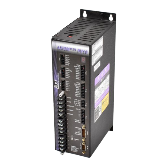
- Page 1 ELECTRIC LINEAR MOTION PRODUCTS AXIOM ® PLUS PV Series Brushless Servo Controller/Drive User Manual TOL-O-MATIC, INC Excellence in Motion ® 3600-4628_05 For Sales and Support, Contact Walker EMD • Toll-free: (800) 876-4444 • Tel: (203) 426-7700 • Fax: (203) 426-7800 • www.walkeremd.com...
- Page 2 Cables: Use only Tol-O-Matic supplied cables, or cables deemed suitable for use by a competent person familiar with the electrical and mechanical requirements of a given application.
-
Page 3: Table Of Contents
Contents Contents ........................i List of Figures ......................v Introduction ......................ix Graphic Symbols and Warning Classifications ............ix Notices........................x Axiom Plus System Overview ................xiii Power Ratings ....................xiii Interface Cables ....................xiv Axiom Plus Features .....................xiv Motor/Encoder Input..................xv Encoder Follower Input...................xv Encoder Output ....................xv Digital I/O .......................xvi Ac Input Power ....................xvi Drive and Motor Protection Circuitry ............xvi Agency Approvals ...................xvi... - Page 4 C O N T E N T S Chapter 7: Software Installation Hardware and Software Requirements.............7-1 Installation......................7-1 Chapter 8: Initial Check Out Setup/Configuration Screen ................8-1 Commands, Setup and Configuration Mode..........8-3 Indexer Model Selection/Setup ..............8-3 Motor Model Selection/Setup...............8-4 Phasing Configuration.................8-4 Gains and Limits..................8-5 Register Precision ..................8-5 ModBus Configuration ................8-6 Check Out Procedure ..................8-7...
- Page 5 C O N T E N T S Creating / Editing a PLC Rung ..............12-30 Operation Details Screen ................12-31 Default PLC Program.................12-44 Chapter 13: Communication/Protocol ASCII Command ....................13-1 RS232 Serial Communications Character Framing Settings....13-1 Read /Write Register Value Using ASCII Commands Over RS232 Serial Port ....................13-1 Reading Indexer Internal Fault and Status Identification Flag Words ...13-5 Reading Process Variable/Diagnostic Registers.........13-6...
- Page 6 Appendix B: Specifications Agency Approvals....................B-1 Power .......................B-1 Command Sources ....................B-2 Serial Communication Port ................B-2 Control Loops....................B-2 Inputs and Outputs ..................B-2 Connectors ....................B-2 Environmental.....................B-3 Motor Protection....................B-3 Regeneration Ratings ..................B-3 Power Dissipation....................B-4 Appendix C: Motor Performance Data Motor Drive Performance Curves for MRV Series Motor Drives ....C-1 Appendix D: Motor Dimension Drawings Motor Dimension Drawings................D-1 Appendix E: Warranty Information...
-
Page 7: List Of Figures
List of Figures Figure Description Page Axiom PV10 Mounting Dimensions ....... . . 4-2 Axiom PV20 and Axiom PV30 Mounting Dimensions. - Page 8 L I S T F I G U R E S Figure Description Page 9.18 Axiom Plus Sinking Output Connected to Sourcing Opto22 Solid State Relays . . 9-12 9.19 Axiom Plus Power Off Holding Brake Connection ..... . 9-12 10.1 Brake Connection &...
- Page 9 Sequential Program Listing ........14-8 RS-232 Communications Cable (P/N 3600-1172) ..........A-1 Encoder Output Cable (P/N 3604-1213) ............A-2 Tol-O-Matic MRV Motor Connector Pinouts ............A-4 MRV 11Y PV10 Single-Phase, Three-Phase Drive Performance Curves....C-1 MRV 21Y PV10 Single-Phase, Three-Phase Drive Performance Curves....C-2 MRV 22Y PV10 Single-Phase, Three-Phase Drive Performance Curves....C-2...
- Page 10 viii For Sales and Support, Contact Walker EMD • Toll-free: (800) 876-4444 • Tel: (203) 426-7700 • Fax: (203) 426-7800 • www.walkeremd.com...
-
Page 11: Introduction
Introduction This manual provides step-by-step instructions for installing, controlling, tuning and maintaining your Tol-O-Matic Axiom Plus system. It details the hardware connections necessary to operate this unit in each of its operating modes. All Axiom series drives use Tol-O-Motion™ Axiom® setup software installed on a personal computer running Microsoft Windows®... -
Page 12: Notices
I N T R O D U C T I O N NOTICES Danger Notices DANGER! Adjustment, operation and service of this equipment should only be performed by qualified electrical personnel familiar with its operation and hazards. Read and understand this manual before attempting installation or operation of this equipment. - Page 13 WARNING! Large leakage currents exist in AC line filters. They must be grounded properly before applying power. Filter capacitors retain high voltages after power removal. Before handling the equipment, voltages should be measured to determine safe levels prior to handling the equipment. Failure to observe this precaution could result in severe bodily injury.
- Page 14 Caution! If the cabinet is ventilated, use filtered or conditioned air to prevent the accumulation of dust and dirt on electronic components. The air should be free of oil, corrosives, or electrically conductive contaminates. For Sales and Support, Contact Walker EMD • Toll-free: (800) 876-4444 • Tel: (203) 426-7700 • Fax: (203) 426-7800 • www.walkeremd.com...
-
Page 15: Axiom Plus System Overview
Axiom Plus PV30 with a continuous current rating of 15A and a peak rating of 30A from a single or three phase power source. The Axiom Plus system, when combined with Tol-O-Matic MRV series brushless servo motors, can provide continuous torque up to 75 lb-in (10.7 Nm), peak torque up to 150 lb-in (21.4 Nm) and speeds... -
Page 16: Interface Cables
INTERFACE CABLES Standard motor power and encoder feedback cables, as well as communications cables, are available to complete the motion control system and provide reliable, trouble free start-up. For a description of optional equipment, refer to Appendix A: Options and Accessories. Axiom Plus System Features Sequential Motion Control - An easy to use sequential motion control programming environment. -
Page 17: Motor/Encoder Input
Built-in real-time scanned “PLC” for complex machine control tasks • Encoder Follower input • Designed for use with Tol-O-Matic MRV series brushless motors. • Pluggable terminal block connections for ease of Installation. • Continuous output ratings of 5A, 10A and 15A. -
Page 18: Ac Input Power
I/O – INPUT OUTPUT The Axiom Plus unit incorporates several dedicated discrete I/O connections. • Brake Relay Output - A 3A relay contact for connection to an actuator or motor shaft-mounted “energize-to-release”-type brake. • Motor Temp Input - Connection for a motor’s internal temperature switch. -
Page 19: Agency Approvals
Windows-based graphical interface that communicates through the drive’s RS-232 serial communications port. Windows 95, 98, NT and XP are supported. • The software allows easy selection of any Tol-O-Matic MRV series brushless servo motor. • The software provides a user friendly “on-screen” oscilloscope and diagnostic screen for tuning and troubleshooting. - Page 20 xviii For Sales and Support, Contact Walker EMD • Toll-free: (800) 876-4444 • Tel: (203) 426-7700 • Fax: (203) 426-7800 • www.walkeremd.com...
-
Page 21: Chapter 1: Safety
Safety Before you begin... Please read this manual in its entirety before attempting to install or operate the unit. In this way, risk of injury, damage or wasted time and effort can be minimized. Potential Hazards The equipment described in this manual is intended for use in industrial drive systems. -
Page 22: Your Responsibilities
As the user or person installing this product, you are responsible for determining the suitability of the product for the intended application. Tol-O-Matic is neither responsible nor liable for indirect or consequential damage resulting from the inappropriate use of this product. - Page 23 S A F E T Y Stored energy hazards are both electrical and mechanical. 1. Electrical hazards can be avoided by disconnecting the Axiom Plus from its power source and waiting for the time indicated in the warning on the front of the unit prior to removing the protective covers or touching any connections.
- Page 24 S A F E T Y 1 - 4 For Sales and Support, Contact Walker EMD • Toll-free: (800) 876-4444 • Tel: (203) 426-7700 • Fax: (203) 426-7800 • www.walkeremd.com...
-
Page 25: Chapter 2: Theory Of Operation
Theory of Operation Discussion of Drive Technologies Axiom Plus units include a state-of-the-art Vector drive designed to drive three-phase brushless servo motors. This type of drive offers several performance improvements over conventional “six-step,” “trapezoidal,” or “sine” commutation brushless servo drives. Three-Phase Brushless Motors Three-phase brushless servo motors employ a three-phase, wye- connected motor winding wound on the stator, or stationary outer... -
Page 26: Commutation
T H E O R Y O P E R A T I O N Commutation Any time electrical current flows in a wire or coil of wires, a magnetic field is created. In a motor, this magnetic field is used to generate torque at the motor shaft output. -
Page 27: Brushless Servo Drives
T H E O R Y O P E R A T I O N : 2 BRUSHLESS SERVO DRIVES In order to provide servo performance with permanent magnet brushless servo motors, several different commutation and current control schemes have been used. These can be grouped into three main types: Hall Commutated Drives, Sine Commutation Drives, and Vector Drives. -
Page 28: Sine Commutated Drives
T H E O R Y O P E R A T I O N vector lags behind the commanded voltage vector by an increasing amount. This causes the torque to roll off with speed, even though the motor current remains constant. Sine Commutation Drives By employing more modern microcontroller technology to brushless servo drives, sine commutation can be achieved. -
Page 29: Vector Drives
T H E O R Y O P E R A T I O N Since phase lag is such a major problem at higher speeds, many drives attempt to solve the phase lag problem by introducing a “phase advance” factor into their voltage vector calculation. This advances the three rotating voltage vectors by an amount equal to the expected current phase lag for a given speed. - Page 30 R-L time constant induced phase lag are automatically compensated for in the algorithm. All Tol-O-Matic MRV motors can be driven from zero speed to full rated speed with negligible torque ripple or loss of torque due to tolerance or current phase lag issues.
-
Page 31: Unpacking The Drive
Inspection Procedure To protect your investment and ensure applicable warranty rights, Tol-O-Matic recommends the unit be carefully inspected for any signs of physical damage. If any damage is detected, contact the purchasing agent to make a claim with the shipper. - Page 32 U N P A C K I N G , I N S P E C T I O N & S T O R A G E 3 - 2 For Sales and Support, Contact Walker EMD • Toll-free: (800) 876-4444 • Tel: (203) 426-7700 • Fax: (203) 426-7800 • www.walkeremd.com...
- Page 33 Physical Mounting of the Drive 1. This unit must be mounted in a proper electrical enclosure providing protection to IP54 (protected against dust and splashing water), or IP65 (dust free and protected against water jets) where the environment is poor. Many NEMA (National Electrical Manufacturers Association) Type 4 cabinets provide this level of protection.
- Page 34 EXT REGEN A – INT REGEN B – I – COM/SHLD MOT TEMP ENCODER ——— ENCODER FOLLOWER TOL-O-MATIC HAMEL, U.S.A. WARNING: VOLTAGE EXISTS UP TO 2 MIN. AFTER POWER IS REMOVED 0.23" [REF] (5.7) 3.87" (98.2) Figure 4.1 - Axiom PV10 Mounting Dimensions 4 - 2 For Sales and Support, Contact Walker EMD •...
- Page 35 B – I – COM/SHLD MOT TEMP ENCODER ——— ENCODER FOLLOWER TOL-O-MATIC HAMEL, U.S.A. WARNING: VOLTAGE EXISTS UP TO 2 MIN. AFTER POWER IS REMOVED .23" [REF] (5.7) 4.84" (122.9) Figure 4.2 - Axiom PV20 and Axiom PV30 Mounting Dimensions 4 - 3 For Sales and Support, Contact Walker EMD •...
- Page 36 P H Y S I C A L M O U N T I N G T H E D R I V E 4 - 4 For Sales and Support, Contact Walker EMD • Toll-free: (800) 876-4444 • Tel: (203) 426-7700 • Fax: (203) 426-7800 • www.walkeremd.com...
-
Page 37: General Wiring Guidelines
Power Connections & Fusing DANGER! The user is responsible for conforming with all applicable local, national and international codes. Wiring practices, grounding, disconnects and overcurrent protection (fusing) are of particular importance. Failure to observe this precaution could result in severe bodily injury or loss of life. -
Page 38: Axiom Plus Pv10, Pv20, Pv30
P O W E R C O N N E C T I O N S & F U S I N G Axiom Plus PV10, PV20 & PV30 Axiom Plus systems operate from single or three phase power, 50/60Hz. Nominal input ranges are 115Vac or 208/230Vac. The switch on top of the unit should be set to reflect the proper range. -
Page 39: General Wiring Guidelines
Motor Encoder & Power Connections This chapter contains information about proper connection of motor power and encoder wiring. For additional information on Tol-O-Matic motor performance specifications please refer to Appendix C. WARNING! Never connect or disconnect motor power connections when power is applied to the unit. To do so could cause electrical shock or result in severe arcing and may damage the motor or Axiom Plus. -
Page 40: Axiom Plus Systems
PHASE S BLUE PHASE T Figure 6.1 - PV10/20/30 Motor Power Cable Connections for MRV 2X, 3X Proper encoder phasing is necessary for proper motor operation. The following color codes apply to Tol-O-Matic cables. MRV11 ENC +5V Brown Orange White... -
Page 41: Emergency Stop Connection
M O T O R E N C O D E R & P O W E R C O N N E C T I O N S Emergency Stop Connection Emergency stop can be implemented in a number of ways depending on the application requirements. - Page 42 M O T O R E N C O D E R & P O W E R C O N N E C T I O N S E-STOP RELAY PHASE 3 PHASE 2 PHASE 1 EARTH GROUND Figure 6.4 - Drive Remains Powered 6 - 4 For Sales and Support, Contact Walker EMD •...
-
Page 43: Chapter 7: Software Installation
Software Installation This chapter provides information about installation of Tol-O- Motion Axiom software on a personal computer. Hardware and Software Requirements • A personal computer running Microsoft Windows 95, 98, NT or XP • A hard disk with 10 MB of free disk space •... - Page 44 S O F T W A R E I N S T A L L A T I O N 7 - 2 For Sales and Support, Contact Walker EMD • Toll-free: (800) 876-4444 • Tel: (203) 426-7700 • Fax: (203) 426-7800 • www.walkeremd.com...
-
Page 45: Chapter 8: Initial Check Out
Initial Check Out It is strongly recommended that an initial check out be performed on the motor-drive combination at this time. This should be done with the motor disconnected from the load. This procedure will verify that the correct motor is chosen and that it is connected and phased properly before proceeding further. - Page 46 I N I T I A L C H E C K O U T 5. From the opening screen, select COMM1, COMM2, COMM3, or COMM4. Then choose “Axiom Plus Indexer Setup/Config” Figure 8-2 - Set-Up and Configuration Screen The Setup and Configuration screen is divided into seven sections, which are labeled as follows: 1) Commands, Setup and Configuration Mode 2) Indexer Model Selection / Setup...
-
Page 47: Commands, Setup And Configuration Mode
Note: This Axiom Plus unit is not configured for use with non-Tol- O-Matic motors. For use of the unit with a non-Tol-O-Matic motor, please contact the sales representative from whom this unit was purchased. -
Page 48: Motor Model Selection/Setup
MOTOR MODEL SELECTION / SETUP When the Select Standard Motor button (above) is pressed, a dropdown menu of Tol-O-Matic brushless servo motors appears in this section. Only those motors which are compatible with the selected drive will be displayed. Once a choice is made, the motor data associated with that choice will be displayed. -
Page 49: Gains And Limits
I N I T I A L C H E C K O U T GAINS AND LIMITS This section displays the tuning values associated with the parameters uploaded to the workspace, as well as coding input calibration parameters. On the initial startup, the values appearing are simply placeholders. -
Page 50: Modbus Configuration
I N I T I A L C H E C K O U T MODBUS CONFIGURATION This section shows the current configuration of the unit as it relates to ModBus setup and addressing. In order to use this feature, the drive must be operating in ModBus Mode. -
Page 51: Check Out Procedure
“Upload Complete” should appear on the screen. The first time this is done, placeholder parameters will be displayed. 3. Choose the correct Tol-O-Matic motor from the list displayed. 4. Set Phasing Torque and Phasing Degree as required by your application (see above). - Page 52 I N I T I A L C H E C K O U T 8 - 8 For Sales and Support, Contact Walker EMD • Toll-free: (800) 876-4444 • Tel: (203) 426-7700 • Fax: (203) 426-7800 • www.walkeremd.com...
-
Page 53: Chapter 9: I/O Connections
I/O Connections Inputs Caution! The maximum voltage that can be applied to an input terminal is 25 VDC The Axiom Plus provides 15 optically isolated inputs if analog input is not used. The inputs can be configured to sink or source current (5VDC –... - Page 54 Forward Limit Black Closed COM x-y Form C Normally Reed Switch Blue INPUT Open INPUT INPUT Brown Home Switch INPUT Black Tol-O-Matic Sourcing INPUT Blue Hall Effect INPUT Brown Reverse Limit Normally Black Closed Form C Normally Reed Switch Blue Open Push Button Figure 9.2 - Axiom Plus Sinking Input Connected to Sourcing Switches Using Internal...
- Page 55 I / O C O N N E C T I O N S : Sourcing Output Sinking Input PLC or Motion AxiomPlus Controller +24 Vdc 24Vdc RTN OUT 0 OUT 1 COM x-y INPUT OUT 2 INPUT OUT 3 INPUT OUT 4 OUT 5...
- Page 56 Black COM x-y Reed Switch Normally Normally Blue INPUT Open Closed Contact INPUT INPUT Brown Home Switch INPUT Black Tol-O-Matic Sinking INPUT Blue Hall Effect INPUT Brown Forward Limit Normally Form C Black Closed Reed Switch Push Button Normally Normally...
- Page 57 I / O C O N N E C T I O N S : Sinking Output Sourcing Input PLC or Motion AxiomPlus Controller +24 Vdc OUT 0 24Vdc RTN OUT 1 COM x-y OUT 2 INPUT INPUT OUT 3 OUT 4 INPUT OUT 5...
- Page 58 I / O C O N N E C T I O N S Analog Input Specifications and Hardware Connections Analog input hardware and functionality has been added to this series of Axiom+ PV-series. This hardware allows connection of a fully differential analog source using “dual-use”...
- Page 59 I / O C O N N E C T I O N S : to input terminal 13 will also serve as analog common. If the analog input is used, terminal 15 is considered “no connection”. • Input 13, 14 and 15 will still be available if the analog input function is not used.
-
Page 60: Analog Inputs
I / O C O N N E C T I O N S Following is a list of performance specifications and hardware connection issues related to the analog input feature. Analog Input Resolution 14 bit Specified input range +/- 10 volts Conversion range +/- 7782 Effective resolution... -
Page 61: Outputs
I / O C O N N E C T I O N S : Outputs The Axiom Plus has 8 programmable outputs. The outputs are optically isolated, meaning there is no electrical connection between the controller and the output terminals. The signal is transmitted to the output circuit as light. - Page 62 I / O C O N N E C T I O N S Sinking Input Motion Controller or PLC Sourcing Output AxiomPlus IN 0 IN 1 +24 Vdc IN 2 24Vdc RTN IN 3 OUT + IN 4 OUT - IN 5 OUT + IN 6...
- Page 63 I / O C O N N E C T I O N S : Sourcing Input Motion Controller or PLC Sinking Output AxiomPlus +24 Vdc 24Vdc RTN OUT + OUT - OUT + OUT - Figure 9.16 - Axiom Plus Sinking Output Connected to Sourcing Input Using Internal Power Supply Sourcing Input PLC...
- Page 64 I / O C O N N E C T I O N S Solenoid Light 24VDC Power Supply DC Output Module Neutral 0 VDC + VDC Line OPTO22 G4PB4R Amplifier Sinking Output AxiomPlus +24 Vdc 24Vdc RTN OUT + OUT - OUT + OUT -...
- Page 65 Axiom PV series application. Never connect both, as this may destroy the internal switching circuitry. All Tol-O-Matic Axiom Plus units incorporate a brake relay. This is designed for use with an “energize-to-release” type of load brake.
- Page 66 1 0 : R E G E N E R A T I O N R E S I S T O R U S E & S I Z I N G NOTE: Always wire a snubber circuit in parallel with the brake coil unless the coil has one internally wired.
-
Page 67: Online Tuning And Diagnosis
Final Checkout & Tuning Axiom Plus units always operate in “position” mode. The position command is generated by the internal trajectory generator and applied as a digital command to the unit’s position loop. The error position is continuously calculated and used to derive a command velocity. -
Page 68: Indexer Status, Fault, I/O
1 1 : F I N A L C H E C K O U T & T U N I N G “drive enable” are not met, the drive will remain disabled, regardless of the state of the software enable/disable function. Drive Stage Tuning/Diagnosis This button allows the user to toggle the screen functionality between Tuning and Diagnosis modes. -
Page 69: Oscilloscope
F I N A L C H E C K O U T & T U N I N G : 1 1 In the event that a fault condition does exist, the fault code will be displayed (matching the fault code flashing on the unit’s LED) and a button labeled “Description”... -
Page 70: Encoder Feedback Section
1 1 : F I N A L C H E C K O U T & T U N I N G • Trigger Source – This displays the parameter whose change will trigger the sweep to begin. The user can define this by clicking on the Trigger button. -
Page 71: Drive Tuning Screen
F I N A L C H E C K O U T & T U N I N G : 1 1 engage the monitoring function, press the Active button in one of the three windows, and watch for the window header to change from white to green text. - Page 72 1 1 : F I N A L C H E C K O U T & T U N I N G Auto tuning. The word “Manual” in this case refers to the control of the trajectory generator, and not the tuning method. Unit-Step Set-Up –...
-
Page 73: Drive Tuning
F I N A L C H E C K O U T & T U N I N G : 1 1 value is exceeded during operation, the Axiom Plus will fault out (“F55”). Ipb (In-Position Band) Any time the unit’s following error is less than or equal to this number, the In Position state will be true(1). -
Page 74: Manual Tuning
1 1 : F I N A L C H E C K O U T & T U N I N G drive may then be fine tuned for better response. Auto-tune step parameters (torque level and time duration) can be adjusted if necessary to improve auto-tuning. - Page 75 F I N A L C H E C K O U T & T U N I N G : 1 1 Figure 11.3 Tuning and Diagnostics Screen with Analog Input Calibration Function active • Note: The scroll bar adjustments are "live", i.e. any change in analog input gain or offset is immediately effective, and values are stored in indexer non-volatile EEPROM memory as they are changed.
- Page 76 1 1 : F I N A L C H E C K O U T & T U N I N G value that is used by the indexer for all analog functionality during application run-time operation. This displayed voltage will always reflect the active scale factor and offset adjustments set by the user.
-
Page 77: Chapter 12: Programming
Programming The operating environment of the Axiom Plus consists of two separate parts or “threads”. These are the sequential program and the PLC program. The sequential program executes actual move commands and is programmed using the Sequential Program editor. The PLC program is a scanned logic program that operates like a stand alone Programmable Logic Controller (PLC). -
Page 78: Programming Environment
1 2 : P R O G R A M M I N G events that occur asynchronously with respect to the main sequential program. Programming Environment The Axiom Plus programming platform consists of a sequential program editor and a PLC program editor. Only one of these editors can be open at a time, but the user can move back and forth between the sequential and PLC editors without losing the work in progress in a given editor. -
Page 79: Prg Menu
P R O G R A M M I N G : 1 2 The above screen will appear consisting of an editing window and a menu of buttons. These buttons are used to select the desired action, and their function is described below: PRG MENU UPLOAD FROM INDEXER This will upload the sequential program (and its associated... - Page 80 1 2 : P R O G R A M M I N G Figure 12.2 - Register Display Screen I/O FLAG TABLE Display a list of the I/O and PLC bit flags, and allows comments to be inserted here. The “double-star” icon in the USED? Column indicates that this I/O or flag is being used by the sequential motion program or the PLC program.
-
Page 81: Sequential Program Debugger
P R O G R A M M I N G : 1 2 SEQUENTIAL PROGRAM DEBUGGER A method of debugging a sequential program is available to the user when testing a sequential program. A button labeled "Debug Program" has been added to the Sequential Program user menu. The Debugger allows the user to single step through the Sequential Program and to view and modify the values of flags and registers. - Page 82 1 2 : P R O G R A M M I N G Register" or "Watch Flag" items brings up the Watch Window, which displays the watched register’s description and its current value. Figure 12.5 - Watched Registers & Flags If the user double clicks on an item in the watch window, a dialog box pops up that allows the user to enter a new value for the register or flag.
-
Page 83: User Units
Encoder Counts/Unit Once the unit label is selected above, ‘counts per unit’ needs to be entered. Standard Tol-O-Matic brushless servo motors use a 1000 line encoder operating in quadrature, equaling 4000 counts/rev. (Example: A 2-turns-per-inch screw has 2 x 4000=8000 counts/inch). -
Page 84: Sequential Program Listing
1 2 : P R O G R A M M I N G SEQUENTIAL PROGRAM LISTING Figure 12.7- Sequential Program Listing Screen A single program instruction consists of the following four parts: Icon - An icon is a visual representation of the type of instruction being used. -
Page 85: Creating A Sequential Motion Program Instruction
P R O G R A M M I N G : 1 2 Label - Provides a location that the program can branch to, or indicates the beginning of a subroutine. The label acts as identification of a specific program line. Line number / Parameters - All the instruction parameters are displayed when the mouse is placed over this portion of the program line. -
Page 86: Instruction Command Set
1 2 : P R O G R A M M I N G INSTRUCTION COMMAND SET The program instructions are divided into groups based on function. From the instruction type selection window (above), select the type of instruction needed, then select the specific instruction. AXIS MOTION This group of instructions sets the type of axis motion desired. - Page 87 P R O G R A M M I N G : 1 2 Figure 12.10 - Absolute Position Move Window In addition, the user may embed up to two event triggers in a given move. Each one of these event triggers can cause up to two actions to take place.
-
Page 88: Analog Input Position Mode
1 2 : P R O G R A M M I N G VELOCITY MOVE Commands the axis to accelerate and move at a defined velocity. The motion can be modified or terminated using an event trigger, as described above. ANALOG INPUT POSITION MODE This sequential instruction has been provided to allow control of absolute position command via the analog input. -
Page 89: Analog Input Velocity Mode
P R O G R A M M I N G : 1 2 Figure 12.11 - Sequential Instruction Form for Programming of Analog Absolute Position Control In figure 12.11 the scale factor is programmed for a value of 0.455 inches / volt and the offset for 1.0 inches at zero volts. - Page 90 1 2 : P R O G R A M M I N G setpoint and the actual analog value. Analog Input Velocity Control Mode will initiate velocity tracking of the analog input and will remain active until a logic 1 condition exists for the user selected exit flag.
- Page 91 P R O G R A M M I N G : 1 2 ANALOG VELOCITY CONVERSION FACTOR - This parameter allows setting a gain relating commanded velocity in user units / second to the analog input value in volts. The figure shows a value of 0.542 inches / volt.
- Page 92 1 2 : P R O G R A M M I N G SET/CLEAR OUTPUT - Sets or clears one of 8 physical outputs. If the output is also used in the PLC the state determined by the PLC takes precedence. SET/CLEAR FLAG - Sets or clears one of the 32 Sequential to PLC flags.
- Page 93 P R O G R A M M I N G : 1 2 Figure 12.14 - Program Control Window BRANCH TO LABEL - Causes the program execution to jump to the designated instruction label. CONDITIONAL BRANCH TO LABEL - Causes program execution to jump to the designated instruction label only if the desired condition is met.
- Page 94 1 2 : P R O G R A M M I N G control to return to the instruction following the “Call Subroutine” instruction. The condition can be a physical input or PLC-to-Sequential flag. The logic state can be selected as logic 1 (true) or logic 0 (false).
- Page 95 P R O G R A M M I N G : 1 2 BRANCH ON REGISTER COMPARE - This sequential program instruction compares the value of a register to a fixed value, or to a value in another register, then to branch to a labeled instruction.
- Page 96 1 2 : P R O G R A M M I N G TIME DELAY (WAIT) - Causes program execution to wait for the selected time period before moving to the next instruction. The allowable range is between 0.01 and 1000 seconds. END PROGRAM - Causes the sequential program to terminate.
- Page 97 P R O G R A M M I N G : 1 2 RATIO FOR ENCODER FOLLOWING - Sets the gear ration for the encoder follower function. The encoder following has a range from 0.0001 to 99.9999. The ratio for the encoder following is calculated by dividing the desired commanded encoder counts by the auxiliary encoder counts.
-
Page 98: Analog Position Conversion Factor
1 2 : P R O G R A M M I N G AXIS HOME TO INDEX PULSE - Causes the actuator to move until it detects the home switch then an index pulse. The home to index pulse routine works by moving in the selected direction until it detects the home switch, it then decelerates to a stop and moves at the creep speed in the opposite direction unit it detects the first index pulse after a transition in the home... - Page 99 P R O G R A M M I N G : 1 2 counts / user unit parameter and the scale factor defining volts per user unit match up. This is because, even when position feedback comes from the analog input, velocity loop closure is still based on the incremental encoder feedback.
- Page 100 1 2 : P R O G R A M M I N G (1/0.9) = - 5 inches. • If the Analog Position Offset is programmed for –5 inches at zero volts, then the analog input range of 0 to 9 volts, will correspond to absolute position of –5 to +5 inches, as desired.
- Page 101 P R O G R A M M I N G : 1 2 software diagnostics referring to encoder counts will correspond to "equivalent" incremental encoder counts based on the analog input and programmed parameters while operating with absolute analog position feedback. Once the “Absolute Position Feedback from Analog Input”...
- Page 102 1 2 : P R O G R A M M I N G Figure 12.20 - Register Manipulation Window SAVE POSITION TO REGISTER – This allows either the Actual position (based on encoder feedback) or the Commanded position (based on the trajectory generator) to be stored into a position register.
- Page 103 P R O G R A M M I N G : 1 2 Figure 12.21 - Increment / Decrement Count Register SAVE ANALOG INPUT VAULE TO REGISTER – This instruction saves the current value of the analog input to a register.
-
Page 104: Plc Program Editor
1 2 : P R O G R A M M I N G PLC Program Editor The PLC Program Editor is a graphical “point and click” application designed to quickly and easily develop a ladder logic program. To create or edit the PLC ladder logic program, click on the “PLC Scan Programming”... - Page 105 P R O G R A M M I N G : 1 2 INSERT ABOVE RUNG Brings up the editing screen for a new rung to be placed above the currently selected rung. INSERT BELOW RUNG Brings up the editing screen for a new rung to be placed below the currently selected rung.
-
Page 106: Creating / Editing A Plc Rung
1 2 : P R O G R A M M I N G CREATING / EDITING A PLC RUNG: By selecting the Insert Above or Insert Below command to create a new rung or by double clicking on an existing rung, the PLC rung editor screen opens either a new rung template or the selected rung. - Page 107 P R O G R A M M I N G : 1 2 Figure 12.24 - Operation Details Screen OPERATION SELECT Use to select the logical function desired for the rung in question. Operations are defied as either inputs or outputs. A rung can have multiple inputs (logical operations) that it evaluates, but a rung can only have a single output.
- Page 108 1 2 : P R O G R A M M I N G Figure 12.25 - Operation Selection Screen The “contact types” available for use with the active rung location will turn blue as you move the mouse over them. There are twelve different operations available, depending on whether you are working on an input or an output.
- Page 109 P R O G R A M M I N G : 1 2 LOGICAL INVERT - This operation inverts the logic state. If the input side logic is true, the output passed to the coil or next operation will be false. If it is false, the output will be true.
- Page 110 1 2 : P R O G R A M M I N G PROCESS VARIABLE COMPARISON – This allows the comparison of current Position, Velocity, Torque or analog input to a pre-defined register value, with either a “>”,“<” or “<window<”...
- Page 111 P R O G R A M M I N G : 1 2 UNLATCH OUTPUT COIL - When the rung conditions are true at this coil, it unlatches the associated output. TIMER - There are 16 timers, which can be programmed in .01 second increments.
- Page 112 1 2 : P R O G R A M M I N G COUNTER - There are 16 counters available. The count can be entered directly or a register can be used. Figure 12.29 - Counter Definition Screen Two counter types can be selected. Single Cycle Counter - Counts each false to true transition of the counter rung as one count.
- Page 113 P R O G R A M M I N G : 1 2 OPERAND SELECT Used to select an operand to associate with the operation. The operand is the condition being evaluated by the operation, in order to determine the logic state. This can be an external variable, such as a physical inputs, or internal variables, such as bit flags.
- Page 114 1 2 : P R O G R A M M I N G ONE-SHOT FLAGS (ONS) - Stores the output state of the one of the 16 associated one-shot operations available for use in the ladder-logic program. TIMER FLAGS (TMR) - Holds the output state of one of the associated 16 timer operations available.
- Page 115 P R O G R A M M I N G : 1 2 PC disable asserted (IS007) - This bit flag is true if the disable state is being forced by PC via serial communications. PC step mode asserted (IS008) - This bit flag is true if the PC has set the controller in step mode for manual or auto-tuning.
- Page 116 1 2 : P R O G R A M M I N G PC Debug PRG JOG - (ICS012) - User is jogging - from debug mode. FORCING FLAGS (FF) - The 64 forcing flags are used with either ModBus or ASCII interface.
- Page 117 P R O G R A M M I N G : 1 2 operation enables the drive. The internal condition for the drive to enable are that no faults exist. This command needs to be maintained for the drive to stay enabled. Figure 12.31 - Indexer Control Flags Screen Cycle Start Command (ICC002) - The cycle start output coil starts the sequential program running.
- Page 118 1 2 : P R O G R A M M I N G program will move on to the next command. The pause command will take precedence over the resume command. If the pause command is being held true the cycle will not resume.
- Page 119 P R O G R A M M I N G : 1 2 CW Travel Limit Flag (ICC011) - This is used to define the physical input or conditions that the CW travel limit switch is connected to. When the switch is activated during normal operation, the drive will fault and display the limit switch fault L01 on the front panel LED and the motor will be commanded to stop immediately.
-
Page 120: Default Plc Program
1 2 : P R O G R A M M I N G DEFAULT PLC PROGRAM The Axiom Plus ships with a default PLC program that will allow the controller to run as a simple sequential controller with little or no modifications to the PLC program. - Page 121 P R O G R A M M I N G : 1 2 Input/Output # Comment Usage IN 1 enab_in Enables the drive stage, required before motor can move. IN 2 cstartPB Cycle start push button, this input starts the sequential program.
- Page 122 1 2 : P R O G R A M M I N G 12-46 For Sales and Support, Contact Walker EMD • Toll-free: (800) 876-4444 • Tel: (203) 426-7700 • Fax: (203) 426-7800 • www.walkeremd.com...
-
Page 123: Ascii Command
Communication / Protocol ASCII Command Axiom+ products support registers and discrete flags that can be manipulated via general ASCII commands over the serial (RS232) port. Both RAM and non-volatile registers are provided. These registers can be programmed in place of hard-entered values for position, velocity, and torque-limit throughout the sequential program. - Page 124 1 3 : C O M M U N I C A T I O N / P R O T O C O L Position Ram Registers Read: UR81XXXX XXXX is register id (1-32), Ascii-coded hex Returns: A 32-bit signed integer register value is returned as Ascii-coded hex Write: UW81XXXXYYYYYYYY XXXX is register id (1-32), Ascii-coded hex...
- Page 125 C O M M U N I C A T I O N / P R O T O C O L : 1 3 Torque-Limit RAM Registers Read: UR89XXXX XXXX is register id (1-32), Ascii-coded hex Returns: 16-bit integer register value is returned as low word of 32-bit integer, Ascii-coded hex Write: UW89XXXXYYYYYYYY XXXX is register id (1-32), Ascii-coded hex...
- Page 126 1 3 : C O M M U N I C A T I O N / P R O T O C O L Timer RAM Registers Read: UR91XXXX XXXX is register id (1-8), Ascii-coded hex Returns: 32-bit integer register value returned as Ascii-coded hex Write: UW91XXXXYYYYYYYY XXXX is register id (1-8), Ascii-coded hex YYYYYYYY is 32-bit integer to be written to register, Ascii-coded hex...
-
Page 127: Reading Indexer Internal Fault And Status Identification Flag Words
C O M M U N I C A T I O N / P R O T O C O L : 1 3 As an example of writing to a position register, assume the user has a serial master connected to an Axiom+. The user wishes to write a value of 8000 encoder counts to non-volatile position register # 17. -
Page 128: Reading Process Variable/Diagnostic Registers
1 3 : C O M M U N I C A T I O N / P R O T O C O L bit 8 : encoder feedback / commutation fault, "F07" bit 9 : fatal PLC fault, display code "F98" bit 10 : fatal seq. -
Page 129: Manipulation Of Plc Flags Using Ascii Serial Port Commands
C O M M U N I C A T I O N / P R O T O C O L : 1 3 Process Diagnostic Register #003 Command velocity - user units or enc cnts / sec as configured. Process Diagnostic Register #004 Actual velocity - user units or enc cnts / sec as configured. - Page 130 1 3 : C O M M U N I C A T I O N / P R O T O C O L Indexer Status Flags 12 total read-only via serial port read-only in PLC Indexer Control 12 total read-only via serial port State Flags read-only in PLC...
-
Page 131: Scaling And Interpretation Of Values Stored In Axiom Plus Registers
C O M M U N I C A T I O N / P R O T O C O L : 1 3 Returns: A 32-bit integer value is returned as Ascii-coded hex, with bits 0-7 representing logic state of outputs 1-8 respectively PLC Local FlagsRead 1 Word: UR0DXXXX XXXX is local flag word id (1-4), Ascii-coded hex... - Page 132 1 3 : C O M M U N I C A T I O N / P R O T O C O L position, encoder counts per second for velocity, and a Q15 value for torque (where 0-32767 is equivalent to 0-100% torque). These values are suitable for use in ASCII commands, since the necessary scaling is typically done by the ASCII master device (PC or intelligent controller).
-
Page 133: General Analog Input Functionality Analog Register
C O M M U N I C A T I O N / P R O T O C O L : 1 3 If user units and a decimal shift of 2 is selected, then a register value of 754 will represent a velocity of 7.54 user units / second, and the firmware will make the appropriate scaling calculations on the fly during execution whenever a velocity register is used as the source... -
Page 134: Modbus Communication Setting
1 3 : C O M M U N I C A T I O N / P R O T O C O L corresponds to –8.500 volts. These analog registers are available for reading and writing by the user via the serial port and ASCII or MODBUS commands. -
Page 135: Addressing Of Slave Axiom Plus Devices
C O M M U N I C A T I O N / P R O T O C O L : 1 3 ModBus RTU protocol communications will support the following framing and baud rate options: Baud rate: 9600, 19200*, 38400, or 57600 baud Start bits: 1 start bit... -
Page 136: Mapping
1 3 : C O M M U N I C A T I O N / P R O T O C O L Mapping AXIOM PLUS REGISTERS INTO MODBUS REGISTERS At present, the following registers are provided for use in Axiom Plus programming: Registers Non-Volatile... - Page 137 C O M M U N I C A T I O N / P R O T O C O L : 1 3 A command accessing register memory that is reserved or in some cases accessing a range including more than one type (position, velocity, torque-limit) of register data will result in an error –...
- Page 138 1 3 : C O M M U N I C A T I O N / P R O T O C O L POSITION REGISTERS — Grouped Sequentially NON-VOLATILE HIGH WORD LOW WORD HIGH WORD LOW WORD ADDRESS ADDRESS ADDRESS ADDRESS...
- Page 139 C O M M U N I C A T I O N / P R O T O C O L : 1 3 VELOCITY REGISTERS — Grouped Sequentially NON-VOLATILE HIGH WORD LOW WORD HIGH WORD LOW WORD ADDRESS ADDRESS ADDRESS ADDRESS...
- Page 140 1 3 : C O M M U N I C A T I O N / P R O T O C O L TORQUE-LIMIT REGISTERS — Grouped Sequentially NON-VOLATILE HIGH WORD LOW WORD HIGH WORD LOW WORD ADDRESS ADDRESS ADDRESS ADDRESS...
- Page 141 C O M M U N I C A T I O N / P R O T O C O L : 1 3 COUNTER REGISTERS NON-VOLATILE HIGH WORD LOW WORD HIGH WORD LOW WORD ADDRESS ADDRESS ADDRESS ADDRESS 40135 0134 40136...
-
Page 142: Axiom Plus Discrete I/O And Flags Into Modbus 0X And 1X Memory Space
1 3 : C O M M U N I C A T I O N / P R O T O C O L PROCESS VARIABLE DIAGNOSTIC REGISTERS — Grouped Sequentially 001-002 (READ ONLY) HIGH WORD LOW WORD ADDRESS ADDRESS 44353 4352... - Page 143 C O M M U N I C A T I O N / P R O T O C O L : 1 3 The following table lists address mapping for Axiom Plus discrete flags into ModBus coil (0X) and input (1X) address space. Physical Inputs mapped into ModBus input space (1X references) –...
- Page 144 1 3 : C O M M U N I C A T I O N / P R O T O C O L Indexer Control State Flags mapped into ModBus input space (1X references) – ModBus access read-only Axiom Plus Discrete ModBus Address...
-
Page 145: Command Stream Handling, Time-Separation Of Commands, Etc
C O M M U N I C A T I O N / P R O T O C O L : 1 3 PLC Local Flags mapped into ModBus coil space (0X references) – ModBus access read-only Axiom Plus Discrete ModBus Address PLC Local Flag 001... -
Page 146: Modbus Commands Supported By Axiom Plus
1 3 : C O M M U N I C A T I O N / P R O T O C O L invalid time-spacing, or if the CRC check fails, no response will be returned. After CRC check, the command handler pulls message data from the buffer, decodes the command, takes the appropriate action, and formulates the correct response message (and load the response bytes into the output buffer) for transmission back to the... - Page 147 C O M M U N I C A T I O N / P R O T O C O L : 1 3 01 Read Coil Status Reads the logical (1 or 0) state of discrete coils (outputs) and flags mapped to ModBus 0X reference addresses.
- Page 148 1 3 : C O M M U N I C A T I O N / P R O T O C O L required in the response data field to hold the value of each 32-bit Axiom Plus register read. The Axiom Plus will not support reads of more than 512 ModBus 4X registers (256 Axiom Plus 32-bit registers).
-
Page 149: Registers
C O M M U N I C A T I O N / P R O T O C O L : 1 3 16 Preset Multiple Registers This command allows a ModBus master to write values to multiple registers residing in Axiom Plus memory, mapped into ModBus 4X register space. - Page 150 1 3 : C O M M U N I C A T I O N / P R O T O C O L bit 1, _fsflag0.1: drive not configured, display code “F99” bit 2, _fsflag0.2: power selection switch fault, “F01” bit 3, _fsflag0.3: bridge hardware fault, “F02”...
-
Page 151: Chapter 14: Examples
Examples Indexer Type Control of the Axiom Plus Requirement: External controller needs to command six different motion sequences in the Axiom Plus Solution: Since six motion sequences are required, use three outputs from the external controller connected to three inputs on the Axiom Plus (IN 10, 11 and 12) to define a binary sequence giving six possible states. - Page 152 1 4 : E X A M P L E S Figure 14.1 PLC Program Listing 14-2 For Sales and Support, Contact Walker EMD • Toll-free: (800) 876-4444 • Tel: (203) 426-7700 • Fax: (203) 426-7800 • www.walkeremd.com...
- Page 153 E X A M P L E S : 1 4 Figure 14.2 PLC Program Listing 14-3 For Sales and Support, Contact Walker EMD • Toll-free: (800) 876-4444 • Tel: (203) 426-7700 • Fax: (203) 426-7800 • www.walkeremd.com...
-
Page 154: Sequential Program Listing
1 4 : E X A M P L E S Figure 14.3 PLC Program Listing Sequential Program Listing: The sequential program is setup using a main loop that will call the required subroutine based on the state of the PLC to Sequential Flag. The sequential program has six conditional subroutine calls in the main loop with the six subroutines following. - Page 155 E X A M P L E S : 1 4 Figure 14.4 Sequential Program Listing 14-5 For Sales and Support, Contact Walker EMD • Toll-free: (800) 876-4444 • Tel: (203) 426-7700 • Fax: (203) 426-7800 • www.walkeremd.com...
- Page 156 1 4 : E X A M P L E S Figure 14.5 Sequential Program Listing 14-6 For Sales and Support, Contact Walker EMD • Toll-free: (800) 876-4444 • Tel: (203) 426-7700 • Fax: (203) 426-7800 • www.walkeremd.com...
- Page 157 E X A M P L E S : 1 4 Figure 14.6 Sequential Program Listing 14-7 For Sales and Support, Contact Walker EMD • Toll-free: (800) 876-4444 • Tel: (203) 426-7700 • Fax: (203) 426-7800 • www.walkeremd.com...
- Page 158 1 4 : E X A M P L E S Figure 14.7 Sequential Program Listing 14-8 For Sales and Support, Contact Walker EMD • Toll-free: (800) 876-4444 • Tel: (203) 426-7700 • Fax: (203) 426-7800 • www.walkeremd.com...
-
Page 159: Chapter 15: Status And Fault Display
“F” — “5” — “5” indicates that the maximum allowable following error has been exceeded. There are two classes of faults in Tol-O-Matic Axiom series servo motor drives. The first class are called Fatal Faults. These indicate that something is seriously wrong with the system and can only be cleared by removing power from the drive. -
Page 160: Fault And Status Codes
1 5 : S T A T U S & F A U L T D I S P L A Y FAULT AND STATUS CODES (Listed in order of decreasing priority). FATAL FAULTS (Requires line power-down, power-up and assertion of enable signal to reset.) F00- Processor Fault - An internal error has occurred in the DSP. - Page 161 S T A T U S & F A U L T D I S P L A Y : 1 5 F54 - Bus Under-Voltage Fault - Bus voltage falls below low-limit. F55 - Maximum Following-Error Fault - (Position modes only), maximum following error reached. This limit is set in the Tol-O-Motion setup software.
- Page 162 1 5 : S T A T U S & F A U L T D I S P L A Y 15 -4 For Sales and Support, Contact Walker EMD • Toll-free: (800) 876-4444 • Tel: (203) 426-7700 • Fax: (203) 426-7800 • www.walkeremd.com...
-
Page 163: Chapter 16: Maintenance & Troubleshooting
Maintenance & Troubleshooting This section provides a description of suggested maintenance activities and an in-depth troubleshooting chart. Maintenance The Axiom drive is designed to function with minimum maintenance. DANGER! DC bus capacitors may retain hazardous voltages after input power has been removed. Before working on the drive, wait the full time interval listed on the warning on the front of the drive. -
Page 164: Troubleshooting Guide
Symptom/Fault Code: F03 - Current feedback fault. Possible Causes: Possible open winding; current feedback circuitry not functioning correctly. Possible Solutions: Check motor cable wiring and motor windings; call your Tol-O-Matic distributor. Symptom/Fault Code: F04 - Current regulation fault. Possible Causes: Drive current regulation out of tolerance; current feedback in “saturation”... - Page 165 M A I N T E N A N C E & T R O U B L E S H O O T I N G : 1 6 Symptom/Fault Code: F06 - Motor over-temperature fault. Possible Causes: Motor thermostat tripped. Possible Solutions: Inadequate motor cooling;...
- Page 166 1 6 : M A I N T E N A N C E & T R O U B L E S H O O T I N G 16-4 For Sales and Support, Contact Walker EMD • Toll-free: (800) 876-4444 • Tel: (203) 426-7700 • Fax: (203) 426-7800 • www.walkeremd.com...
- Page 167 Appendix For Sales and Support, Contact Walker EMD • Toll-free: (800) 876-4444 • Tel: (203) 426-7700 • Fax: (203) 426-7800 • www.walkeremd.com...
- Page 168 For Sales and Support, Contact Walker EMD • Toll-free: (800) 876-4444 • Tel: (203) 426-7700 • Fax: (203) 426-7800 • www.walkeremd.com...
-
Page 169: Cables
Options & Accessories Cables COMMUNICATION CABLES Tol-O-Matic offers a pre-wired RS-232 communication cable for connection between a computer and the drive. This cable is supplied with 9-pin D-sub connectors on both ends. Following is a connection diagram for this cable. -
Page 170: Motor Cables
ENCODER OUT I - RESERVED Figure A.2 - Encoder Output Cable (P/N 3604-1213) MOTOR CABLES Tol-O-Matic offers cables for connection of Axiom PV series brushless servo motors/drives. MRV 1x motors are supplied with flying leads and do not require any special cable connectors. - Page 171 15 m length 3604-1197 Motor cables are offered for Tol-O-Matic MRV 2x, 3x and 5x brush- less servo motors. Cables for MRV 2x and 3x motors should be ordered according to the drive with which they will be used. All cables use shielded, four conductor cable.
- Page 172 ENCODER GROUND N.C. N.C. N.C. Brown +5 VDC ENCODER Figure A.3 - Tol-O-Matic MRV Motor Connector Pinouts A - 4 For Sales and Support, Contact Walker EMD • Toll-free: (800) 876-4444 • Tel: (203) 426-7700 • Fax: (203) 426-7800 • www.walkeremd.com...
-
Page 173: Agency Approvals
Specifications Agency Approvals Refer to agency marks on drive or contact Tol-O-Matic for latest information on agency approvals. Power PV10 Continuous Current Rating ....5A (peak/phase) Peak Current Rating .....10A (peak/phase) Maximum Input Current (Single Phase) . -
Page 174: Command Sources
S P E C I F I C A T I O N S Command Sources Serial Communication Port Type ........RS-232 Baud . -
Page 175: Environmental
S P E C I F I C A T I O N S Environmental Storage Temperature ....-40° to 70° C. Operating Temperature . -
Page 176: Power Dissipation
S P E C I F I C A T I O N S Power Dissipation The Axiom drive dissipates power that results in cabinet heating. The following table lists power dissipation values. Calculate the cabinet cooling requirements using the power dissipation information and formulae below. -
Page 177: Appendix C: Motor Performance Data
Motor Performance Data Tol-O-Matic can provide a range of brushless servo motors to cover a broad range of applications. Following are the torque/speed curves for these motors paired with Axiom Plus drives. Motor Drive Performance Curves for MRV Series Motor Drives... - Page 178 M O T O R P E R F O R M A N C E D A T A MRV Series Motor Drives (continued) MRV21Y PV10 Drive, Single-Phase MRV21Y PV10 Drive, Three-Phase 1.130 1.130 PEAK PEAK PEAK PEAK (1230AC) (230Vac) (1230A (1230AC)
- Page 179 M O T O R P E R F O R M A N C E D A T A MRV23Y PV10 Drive, Single-Phase MRV23Y PV10 Drive, Three-Phase 2.82 2.82 2.26 2.26 1.69 1.69 1.13 1.13 RPM (Revolutions per Minute) RPM (Revolutions per Minute) Figure C.4 - MRV 23Y PV10 Single-Phase, Three-Phase Drive MRV24Y PV10 Drive, Single-Phase...
- Page 180 M O T O R P E R F O R M A N C E D A T A MRV Series Motor Drives (continued) MRV31Y PV10 Drive, Single-Phase MRV31Y PV10 Drive, Three-Phase 2.26 2.26 1.69 1.69 1.13 1.13 RPM (Revolutions per Minute) RPM (Revolutions per Minute) Figure C.6 - MRV 31Y PV10 Single-Phase, Three-Phase Drive MRV31Z PV20 Drive, Single-Phase...
- Page 181 M O T O R P E R F O R M A N C E D A T A MRV32Y PV20 Drive, Single-Phase MRV32Y PV20 Drive, Three-Phase 5.65 4.52 3.39 2.26 1.13 RPM (Revolutions per Minute) RPM (Revolutions per Minute) Figure C.8 - MRV 32Y, PV20 Single-Phase, Three-Phase Drive MRV32Z PV30 Drive, Three-Phase MRV32Z PV30 Drive, Single-Phase...
- Page 182 M O T O R P E R F O R M A N C E D A T A MRV Series Motor Drives (continued) MRV33Y; DV20 DRIVE; SINGLE-PHASE MRV33Y; DV20 DRIVE; THREE-PHASE 6.78 6.78 5.65 5.65 4.52 4.52 3.39 3.39 2.26 2.26...
- Page 183 M O T O R P E R F O R M A N C E D A T A MRV51Y PV30 Drive, Three-Phase MRV51Y PV30 Drive, Single-Phase 22.6 22.6 16.9 16.9 PEAK PEAK PEAK PEAK (1230AC) (230Vac) (1230AC) (230Vac) 11.3 11.3 RPM (Revolutions per Minute)
- Page 184 M O T O R P E R F O R M A N C E D A T A C - 8 For Sales and Support, Contact Walker EMD • Toll-free: (800) 876-4444 • Tel: (203) 426-7700 • Fax: (203) 426-7800 • www.walkeremd.com...
-
Page 185: Motor Dimension Drawings
Motor Dimension Drawings Brushless MRV Motors 1.56 (2) 4.400 .980 1.280 (2) .100 Ø 1.810 B.C. Ø.314 Ø .314 Ø 1.180 MOTOR LEADS #22 AWG 18" MIN LENGTH 6-32 UNC -2B x .25 DP(4) ENCODER CABLE 18" LONG Figure D.1 - MRV 11 Motor 1/4 - 20 UNC 1/8 (3.2) SQ. - Page 186 M O T O R D I M E N S I O N S Brushless MRV Motors Motor Connector Sensor/Feedback Ø .218 (5.54) MS3112E-14-8P Connector Thru (4) EQ. Spaced MS3112E-14-19P as Shown on a Ø 3.875 (98.43) B.C. 0.31" (7.9) 1/8 (3.2) SQ.
-
Page 187: Appendix E: Warranty Information
To ensure accurate processing and prompt return of any Tol-O-Matic product, the following procedure must be followed: 1. Call the nearest distributor of Tol-O-Matic products to obtain a Return Material Authorization (RMA) number. Do not return the drive or any other equipment without a valid RMA number. -
Page 188: Product Support
How you have tried to solve the problem. Distributor & Representative Network Tol-O-Matic has a wide network of distributors that are trained to support our products. If you encounter problems, call the distributor or representative where you purchased the product before contacting the factory. - Page 189 © Copyright 2006 Tol-O-Matic, Incorporated. All rights reserved. Axidyne, Axiom, Tol-O-Matic and Excellence In Motion are registered trademarks of Tol-O- Matic Incorporated. All other products or brand names are trademarks of their respective holders. 04/06 DP For Sales and Support, Contact Walker EMD • Toll-free: (800) 876-4444 • Tel: (203) 426-7700 • Fax: (203) 426-7800 • www.walkeremd.com...
- Page 190 TOL-O-MATIC, INC. 3800 County Road 116 Hamel, MN 55340 763.478.8000 Telephone 763.478.8080 Fax http://www.tolomatic.com For Sales and Support, Contact Walker EMD • Toll-free: (800) 876-4444 • Tel: (203) 426-7700 • Fax: (203) 426-7800 • www.walkeremd.com...
Need help?
Do you have a question about the Axidyne AXIOM PLUS PV Series and is the answer not in the manual?
Questions and answers