Table of Contents
Advertisement
Quick Links
Operation - Repair - Parts
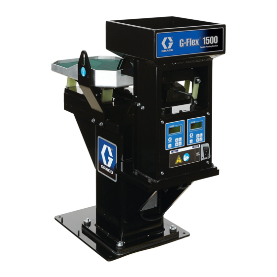
G-Flex 1500 Feeder
- For professional use only -
Model 16V133 - 120V
Vibratory Parts Feeder for separating and presenting parts.
Important Safety Instructions
Read all warnings and instructions in this
manual. Save these instructions.
T A
B L
E
H O
P P
E R
M A
IN
P O
W E
R
ti21442a
332462A
EN
Advertisement
Table of Contents

Subscribe to Our Youtube Channel
Related Manuals for Graco G-Flex 1500

Summary of Contents for Graco G-Flex 1500
- Page 1 Operation - Repair - Parts 332462A G-Flex 1500 Feeder - For professional use only - Model 16V133 - 120V Vibratory Parts Feeder for separating and presenting parts. Important Safety Instructions Read all warnings and instructions in this manual. Save these instructions.
-
Page 2: Table Of Contents
Amplitude Power Setting ....13 Graco Standard Warranty ....34 Limiting Maximum Output of Control . -
Page 3: Warnings
Warnings Warnings The following warnings are for the setup, use, grounding, maintenance, and repair of this equipment. The exclama- tion point symbol alerts you to a general warning and the hazard symbols refer to procedure-specific risks. When these symbols appear in the body of this manual or on warning labels, refer back to these Warnings. Product-specific hazard symbols and warnings not covered in this section may appear throughout the body of this manual where applicable. -
Page 4: Component Identification
Component Identification Component Identification M AI W ER B LE ti21443a Ref. Description Ref. Description Parts Table Left Half M12 Connector Parts Table Right Half Fuses Adjustable Gate Hopper Feed Table Parts Hopper Electromagnet Left Half Lifting Points Electromagnet Right Half Control Display and Touch Pad Electromagnet Hopper Main Power Switch/Lock Out... -
Page 5: Installation
Lifting Instructions Lifting Instructions 2. To mount the G-Flex 1500 postition it in the desired location. The G-Flex 1500 Floor Mounting Plate (J) is designed to be anchored using four 3/8 in. con- crete anchor bolts. To prevent crush injury or equipment damage when lift- ™... -
Page 6: Wiring Connections
Override Mode, 12. Supply Wiring Connections Connect power to the G-Flex 1500 at the Power-in Junc- tion Box (R). See Component Identification, page 4, for location of Junction Box. Use a minimum of 14 AWG solid wires from the power supply. -
Page 7: General Information
Control Menu Power Setting The control uses four programming keys to operate the The G-Flex 1500 comes from the factory set to “Auto control. The power key controls manual operation in Track” for both Amplitude Source and Frequency Mode. override mode. -
Page 8: Start-Up Procedure
9. The table and hopper were Auto Scanned at manu- facture. The serial label below the POWER IN JUNCTION BOX (J) lists the natural frequency of the table and hopper when the G-Flex 1500 was manufactured. ti21922a 15. Press the POWER key on the HOPPER CONTROL TOUCH PAD to turn the hopper OFF. -
Page 9: Operation
Operation Operation BEFORE OPERATING THE G-FLEX 1500, AN AUTO 5. Once the feed rate is determined, record the CFR SCAN MUST BE PERFORMED TO FIND THE value of the part for future reference on the CFR RESONATE FREQUENCY OF THE TABLE AND THE Value table provided on page 31. - Page 10 CFR Value table provided on page 31. NOTE: The chart below illustrates a general rule for operating the G-Flex 1500. Parts with less surface area and more mass will require a greater CFR to move parts around the table.
-
Page 11: Control Menu Layout
[ Normal, Always On, 2-Speed, High/Low ] Empty Bowl [ Normal, Stop ] **Not used on G-Flex 1500 Aux Output Mode [ Normal, Inverted, Alarm, Inv Alarm, Air Jet ] **Not used on G-Flex 1500 Diagnostics Software Version [ Software Revision Level ]... -
Page 12: Manual Operation In Override Mode
Detailed Control Adjustment Manual Operation in Override Setting Minimum Output of Mode Control When the LCD status reads “Stop/Run”, hold the power The Min Amplitude setting can be adjusted to the key for 1.5 seconds. This will start the override operation desired low level of vibration. -
Page 13: Resonate Threshold Level
The resonate frequency is the software revision level show certain software regis- the frequency with the most vibration. Once the best ters that may be helpful to Graco while troubleshooting feeding frequency has been found, fine tune the over the phone. -
Page 14: Language
The CFR set point only appears on the display when the The G-Flex 1500 is rated 3A at 120V and 1.5A at 240V. “Amplitude Source” menu under power settings is set to The operator should monitor the output current to “Auto Track”... -
Page 15: Repair
4. If a spacing adjustment has been made to the tables, perform an Auto Scan, page 7. Table and Brush Spacing The two tables on the G-Flex 1500 need to move inde- Brush Adjustment pendent of each other for optimal operation. It is impor- tant to keep a minimum of .020 in. -
Page 16: Electromagnet And Armature Spacing
Repair Electromagnet and Armature Spacing The spacing between the electromagnet and armature must be .090 in. ti22022a 1. Remove screws (44) holding spring pack (30, 24, 26, 25). 2. Remove and replace spring pack, replace screws - ti21773a hand tighten only. .090 in. -
Page 17: Electromagnet Replacement
Repair Electromagnet Replacement 5. Remove screws (47) from electromagnet (29). Table 1. Disconnect power to the unit. See Power Discon- nect, page 15. 2. Remove display panel (11). See Display (Keypad) Replacement Procedure, page 19 3. Remove electromagnet wiring (29) from harness ti22030a (74) for appropriate electromagnet. - Page 18 Repair 10. Attach wire ends to harness and ground bar. Tighten 4. Remove wire clamps holding wire to hopper. Pull strain relief. wire through hopper frame. ti22038a BLACK BLACK WHITE WHITE GREEN FROM ELECTROMAGNET FROM ti22029a ELECTROMAGNET 5. Remove screws (4) and nuts (15) that attach elec- BLACK WHITE tromagnet (13) to mounting bar (5).
-
Page 19: Display (Keypad) Replacement
Repair 9. Route wire through unit and strain relief. Replace 2. Remove screws (3) from panel (11). cable clamps. ti22036a 10. Attach wire ends to control board and ground bar. Tighten strain relief. ti22000a 3. Remove switch housing on harness (75) from back of switch (76). - Page 20 Repair 5. Remove nut (67) holding ground wire (73). 7. Disconnect ribbon cable from display connector on control board (2 places). ti22003a 6. Disconnect ribbon cables from membrane switch on control board (2 places). ti22005a 8. Replace display panel. 9. Reverse steps for reassembly. ti22004a 332462A...
-
Page 21: Accelerometer Replacement
Repair Accelerometer Replacement 5. Loosen wire clamp and pull wire through pedestal. Remove wire from corrugated sleeving. Table 1. Disconnect power to the unit. See Power Discon- nect, page 15. 2. Remove screws (3) and display panel (11). See Dis- play (Keypad) Replacement Procedure, page 19 3. - Page 22 Repair Hopper 6. Remove screws (19) holding accelerometer (18) to hopper parts feed tray (7). 1. Disconnect power to the unit. See Power Discon- nect, page 15. 2. Remove screws (3) and display panel (11). See Dis- play (Keypad) Replacement Procedure, page 19 3.
-
Page 23: Troubleshooting
Troubleshooting Troubleshooting Problem Possible Cause Solution Parts will not circulate on table Amplitude setting of table is too low Increase amplitude setting of table Frequency setting is not optimal for Autoscan table to find resonant fre- table. quency or manually search for proper frequency. -
Page 24: Parts
Parts Parts 59 59 58 58 19 19 24 24 24 24 24 24 26 26 25 25 24 24 ti22053a 332462A... -
Page 25: Parts List
100270 SCREW, cap, hex hd 121803 SCREW, cap, button head + Included in kit 16W799 REPAIR, table spring pack 183682 LABEL, graco logo * Included in kit 16W800 REPAIR, table pad 58#± 16V557 STRIP, reclosable, fastener, a # Included in kit 16W801 REPAIR, right table 59#±... - Page 26 Parts ti22054a 332462A...
- Page 27 Part Description Qty. 102040 NUT, lock, hex 260212 SCREW, thread forming, hex hd 16V888 LABEL, branding, g-flex 1500 16V346 HOPPER, flex feeder, paint 260067 FITTING, strain relief, 1/2 npt 16V373 BAR, mount, coil, paint 117625 NUT, locking 16V362 SPRING, cantilever, hopper...
-
Page 28: Wiring Diagram
Wiring Diagram Wiring Diagram 332462A... -
Page 29: Technical Specifications
Wiring Diagram Ref. Part Description Qty. Ref. Part Description Qty. 16V823 HARNESS, ground, display 16V775 HOLDER, fuse 16V822 HARNESS, power, jumper,table 16V272 COIL, electromagnetic 16V821 HARNESS, wire, main 16V820 SENSOR, accelerometer,table 16V764 PANEL, mount, circuit bd, complete 16V827 CONNECTOR,M12,5 pin 16X138 HARNESS, ground 16V826 HARNESS, fuse 332462A... -
Page 30: Box Wiring
Wiring Diagram Electrical Component Identification Hopper Coil Hopper Sensor Ground Bar Table Fuse Control Board Hopper Control Board Main Harness Table Sensor ti22031a Table Coil Ref. Part Description Qty. Ref. Part Description Qty. 16V821 HARNESS, wire, main 16V775 HOLDER, fuse 16V764 PANEL, mount, circuit bd, complete 16V272 COIL, electromagnetic 16W665 BAR, ground... -
Page 31: Cfr Values Table
CFR Values Table CFR Values Table Auto Track Mode Manual Mode Part Reference CFR Value Frequency Amplitude 332462A... -
Page 32: Notes
Technical Specifications Technical Specifications G-Flex 1500 (Model 16V133) U.S. Metric Hopper Capacity 0.9 ft 0.25 m Table Size 15.5 in. x 24 in. 39.4 cm x 61.0 cm Maximum Part Size 3 in. x 3 in. x 1.5 in. 7.6 cm x 7.6 cm x 3.8 cm... -
Page 33: Graco Standard Warranty
With the exception of any special, extended, or limited warranty published by Graco, Graco will, for a period of twelve months from the date of sale, repair or replace any part of the equipment determined by Graco to be defective. - Page 34 All written and visual data contained in this document reflects the latest product information available at the time of publication. Graco reserves the right to make changes at any time without notice. This manual contains English. MM 332462 Graco Headquarters: Minneapolis International Offices: Belgium, China, Japan, Korea GRACO INC.
Need help?
Do you have a question about the G-Flex 1500 and is the answer not in the manual?
Questions and answers