Table of Contents
Advertisement
Quick Links
Advertisement
Table of Contents

Related Manuals for Rentquip Patron GI-2000


Summary of Contents for Rentquip Patron GI-2000
- Page 1 GI-2000 INVERTER GENERATOR operation manual...
-
Page 2: Table Of Contents
table of contents Safety Introduction Safety Warnings Safety Information Description 10 Description 11 Control Panel Control Function 12 3 in 1 switch knob 12 Oil warning light (red) 13 Overload indicator light (red) 13 AC pilot light (green) 14 DC protector 14 Engine smart control (ESC) 15 Fuel tank cap 15 Fuel tank cap air vent knob... - Page 3 table of contents Maintenance 25 Maintenance 27 Spark plug inspection 28 Carburetor adjustment 28 Engine oil replacement 29 Air filter 30 Muffler screen and spark Arrester 31 Fuel tank filter 31 Fuel filter Storage 32 Drain the fuel 32 Engine Troubleshooting 32 Engine won’t start 34 Generator won’t produce power...
- Page 4 introduction Attention: Read through the complete manual prior to the initial use of your generator. Using the Operator’s manual The operating manual is an important part of your generator and should be read thoroughly before initial use, and referred to often to make sure adequate safety and service concerns are being addressed.
-
Page 5: Safety Warnings
safety Save these Instructions Safety Warnings This is the safety alert symbol. It is used to alert you to potential personal injury hazards. Obey all safety messages that follow this symbol to avoid possible injury or death. The safety alert symbol ( ) is used with a signal word (DANGER, CAUTION, WARNING), a pictorial and/or a safety message to alert you to hazards. -
Page 6: Safety Information
safety 1. SAFETy INFORMATION Read and understand this owner’s manual before operating your generator. It will help you avoid accidents if you get familiar with your generator’s safe operation procedures. WARNING Generator exhaust contains carbon monoxide, a poisonous gas that can kill you. You CANNOT smell or see this gas. - Page 7 safety WARNING Fuel and its vapors are extremely flammable and explosive. Fire or explosion can cause severe burns or death. When Adding or Draining Fuel • Observe all safety regulations for the safe handling of fuel. Handle fuel in safety containers. If the container does not have a spout, use a funnel.
- Page 8 safety Ground Fault Circuit Interrupter Protection These generators are equipped with a GFCI (Ground Fault Circuit Interrupters) 120V duplex receptacles for protection against the hazards of electrical shock from defective attachments such as, tools, cords, and cables. WARNING • The GFCI may not function unless the generator is properly grounded.
- Page 9 safety This product has been designed with internal grounding or floating bonded neutral. If it should malfunction or breakdown, grounding provides a path of least resistance for electric current to reduce the risk of electric shock. DANGER Improper grounding can result in a risk of electrocution. Check with a qualified electrician for your local requirements if you are in doubt as to whether the unit is properly grounded.
-
Page 10: Description
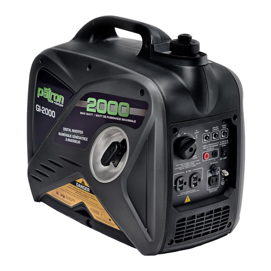
description 3. DESCRIPTION 1. Carrying handle 2. Fuel tank cap air vent knob 3. Fuel tank cap 4. Control panel 5. Recoil starter 6. Oil filler cap 7. Louver 8. Muffler 9. Spark plug maintenance cover... -
Page 11: Oil Warning Light (Red)
description 3.1 Control Panel 1. Oil warning light 2. Overload indicator light 3. AC pilot light 4. ESC (Engine Smart Control) 5. 3 in 1 switch knob (including start/stop switch, fuel valve and choke) 6. AC receptacle 7. DC receptacle 8. - Page 12 control function 4. CONTROl FUNCTION 4.1 3 in 1 switch knob (1) Engine switch\fuel valve “OFF”; Ignition circuit is switched off. Fuel is switched off. The engine will not run. (2) Engine switch\fuel valve\choke “ON”; Ignition circuit is switched on. Fuel is switched on. Choke is switched on.
- Page 13 control function 4.3 Overload indicator light (red) The overload indicator light (1) comes on when an overload of a connected electrical device is detected, the inverter control unit overheats, or the AC output voltage rises. Then, the AC protector will trip, stopping power generation in order to protect the generator and any connected electric devices.
-
Page 14: Engine Smart Control (Esc)
control function 4.5 DC protector The DC protector turns to “OFF” (2) automatically when electric device being connected to the generator is operating and current above the rated flows. To use this equipment again, turn on DC protector by pressing its button to “ON” (1) (1) “ON”... -
Page 15: Fuel Tank Cap
control function 4.7 Fuel tank cap Remove the fuel tank cap by turning it counterclockwise. 4.8 Fuel tank cap air vent knob The fuel tank cap (2) is provided with an air vent knob to (1) stop fuel flow. The air vent knob must be turned to “ON”. This will allow fuel to flow to the carburetor and the engine to run. -
Page 16: Preparation
preparation 5. PREPARATION 5.1 Fuel DANGER • Fuel is highly flammable and poisonous. Check “SAFETY INFORMATION” carefully before filling. • Do not overfill the fuel tank, otherwise it may overflow when the fuel warms up and expands. • After filling, make sure the fuel tank cap is tightened securely. -
Page 17: Pre-Operation Check
preparation 3. Remove the oil filler cap (3). 4. Fill the specified amount of the recommended engine oil, and then install and tighten the oil filler cap. 5. Install the cover and tighten the screws. Recommended engine oil: SAE SJ 15W-40 Recommended engine oil grade: API Service SE type or higher Engine oil quantity: 0.35 L 5.3 Pre-Operation check... -
Page 18: Operation
preparation 6. OPERATION WARNING • Never operate the engine in a closed area or it may cause unconsciousness and death within a short time. Operate the engine in a well ventilated area. • Before starting the engine, do not connect any electric devices. NOTICE •... -
Page 19: Operation
operation 6.1 Starting the engine 1. Turn the ESC switch to “OFF” (1). 2. Turn the air vent knob to “ON” (2). 3. Turn the 3 in 1 switch to “CHOKE” (3), a. Ignition circuit is switched on. b. Fuel is switched on. c. -
Page 20: Stopping The Engine
operation 6.2 Stopping the engine TIP: Turn off any electric devices. 1. Turn the ESC to “OFF” (1). 2. Disconnect any electric devices. 3. Turn the 3 in 1 switch to “OFF” (2), a. Ignition circuit is switched off. b. Fuel is switched off. 4. -
Page 21: Alternating Current (Ac) Connection
operation 6.3 Alternating Current (AC) connection WARNING • Be sure any electric devices are turned off before plugging them in. NOTICE • Be sure all electric devices including the lines and plug connections are in good condition before connection to the generator. •... - Page 22 operation NOTICE • Be sure the ESC is turned off while charging the battery. • Be sure to connect the red battery charger lead to the positive (+) battery terminal ,and connect the black lead to the negative (-) battery terminal.
-
Page 23: Application Range
operation 6.5 Application range When using the generator, make sure the total load is within rated output of a generator. Otherwise, generator damage may occur. Power 0.8-0.95 0.4-0.75 Factor (Efficiency 0.85) Rated 1,600W 1,280W 544W Rated output voltage 12V power TIP: •... - Page 24 operation NOTICE • Do not overload. The total load of all electrical appliances must not exceed the supply range of the generator. Overloading will damage the generator. • When supplying precision equipment, electronic controllers, PCs, Electronic computers, microcomputer based equipment or battery chargers, keep the generator a sufficient distance away to prevent electrical interference from the engine.
-
Page 25: Maintenance
maintenance 7. MAINTENANCE The engine must be properly maintained to ensure its operation is safe, economical and trouble-free, as well as eco-friendly. In order to keep your gasoline engine in good working condition, it must be periodically serviced. The following maintenance schedule and routine inspection procedures must be carefully followed: Items Frequency... - Page 26 maintenance NOTICE • If the gasoline engine frequently works under high temperature or heavy load, change the oil every 25 hours. • If the engine frequently work under dusty or other severe circumstances, clean the air filter element every 10 hours; If necessary, change the air filter element every 25 hours.
-
Page 27: Spark Plug Inspection
maintenance 7.1 Spark plug inspection The spark plug is important engine components, which should be checked periodically. 1. Remove the cap (1), and use the tool (3) remove the spark plug cap (2), and Insert the tool (5) through the hole from the outside of the cover. -
Page 28: Carburetor Adjustment
maintenance 7.2 Carburetor adjustment The carburetor is a vital part of the engine. Adjusting should be left to our company authorized dealer with the professional knowledge, specialized date, and equipment to do so properly. 7.3 Engine oil replacement WARNING • Avoid draining the engine oil immediately after stopping the engine. The oil is hot and should be handled with care to avoid burns. -
Page 29: Air Filter
maintenance 6. Add engine oil to the upper level. Recommended engine oil: SAE SJ 15W-40 Recommended engine oil grade: API Service SE type or higher Engine oil quantity: 0.35L 7. Wipe the cover clean, and wipe up any spilled oil. NOTICE •... -
Page 30: Muffler Screen And Spark Arrester
maintenance The engine should never run without the foam element; excessive piston and cylinder wear may result. 7. Install the air filter case cover in its original position and tighten the screw. 8. Install the cover and tighten the screws. 7.5 Muffler screen and spark arrester WARNING •... -
Page 31: Fuel Tank Filter
maintenance TIP: Align the spark arrester projection (7) with the hole (8) in the muffler pipe. 6. Install the muffler screen and the muffler cap. 7. Install the cover and tighten the screws. 7.6 Fuel tank filter WARNING • Never use the gasoline while smoking or in the vicinity of an open flame. -
Page 32: Storage
storage 8. STORAGE Long term storage of your machine will require some preventive procedures to guard against deterioration. 8.1 Drain the fuel 1. Turn the 3 in 1 switch to “OFF” (1) . 2. Remove the fuel tank cap, remove the filter . Extract the fuel from the fuel tank into an approved gasoline container. -
Page 33: Engine
troubleshooting 8. Install the cover and tighten the screws. 9. Turn the fuel tank cap air vent knob to “OFF” after the engine has completely cooled down. 8.2 Engine Perform the following steps to protect the cylinder, piston ring, etc. from corrosion. -
Page 34: Generator Won't Produce Power
specifications 9.2 Generator won’t produce power · Safety device (DC protector) to “OFF”…. Press the DC protector to “ON”. · The AC pilot light (Green) goes off …. Stop the engine, then restart. 10. SPECIFICATIONS Item GI-2000 Generator Type Silent Inverter Rated frequency (Hz) Rated voltage (v) Rated output power (kW) -
Page 35: Wiring Diagram
wiring diagram 11. WIRING DIAGRAM... -
Page 36: Parallel Function
parallel function 12. PARAllEl FUNCTION INSTRUCTIONS OFF / OFF / ARRÊT ARRÊT OVERLOAD / OVERLOAD / ON / ON / OUTPUT /SORTIE OUTPUT /SORTIE SURCHARGE SURCHARGE MARCHE MARCHE ESC THROTTLE ON ESC THROTTLE ON PARALLEL OPERATION OUTLETS PARALLEL OPERATION OUTLETS CHOKE / CHOKE / STARTER...
Need help?
Do you have a question about the Patron GI-2000 and is the answer not in the manual?
Questions and answers