Page 1
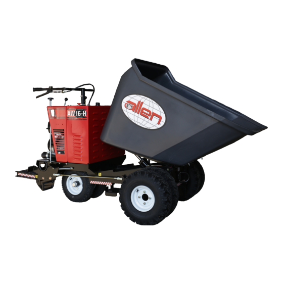
W H E E L B U G G I E S AW16-H & AW21-H SAFETY & OPERATIONS MANUAL Manual Par t #: 05 583 8 | R ev isi on : H Language: E n glish | O r igin a l In stru cti on s...
Page 2
This manual, or a copy of it, must be kept with the machine at all times. There is a manual storage container located on the machine for your convenience. Page 2 055838...
Page 3
OPERATIONS-PARTS MANUAL This manual covers the products listed below: Part No. Description 058806 BUGGY AW16-H POLY BUCKET 13HPR NON FILL 058807 BUGGY AW16-H POLY BUCKET 13HPE NON FILL 058808 BUGGY AW21-H POLY BUCKET 20HPE NON FILL 058801 BUGGY AW16-H POLY BUCKET 13HPR FOAM...
Table of Contents, continued Service ............45 Brake Service .
Page 6
Allen reserves the choice to repair or replace. 2. If Allen chooses to replace the part, it will be at no cost to the customer and will be made available to the Allen Distributor, Dealer, or Rental Center from whom the End User purchased the product.
Page 7
Complete any warranty requirements as specified by the engine manufacturer in their instructions found inside the manual box located on the back of the riding trowel operator’s seat. Your engine and clutch is not manufactured by Allen Engineering Corporation, Inc, and therefore is not covered under Allen Engineering Corporation, Inc warranty.
Page 8
Dealer Information Your Dealer has Allen Engineering Corporation trained mechanics and original Allen replacement parts. Always contact the Allen Dealer who sold you this machine for Allen Certified repairs and replacement parts. Place Allen Dealer information below for future reference...
Page 9
Ordering Parts Section 4.0 (page 71) contains illustrated parts lists for help in ordering replacement parts for your machine. Follow the instructions below when ordering parts to insure prompt and accurate delivery: All orders for service parts - include the serial number for the machine. Shipment will be delayed if this information is not available.
Page 10
Model Number - Serial Number Codes Manufacturer’s Codes: When ordering parts or requesting service information, you will always be asked to specify the model and serial numbers of the machine. The legends below specifically defines each significant character or group of characters of the Model Number and Serial Number codes.
Page 11
Unit Identification Unit Identification Plate Location: An identification plate listing the model number and the serial number is attached to each unit and is located on the rear lower left side of mainframe. Refer to Figure 1 for serial number and model number location. This plate should not be removed at any time.
Page 12
[8 mm]). Machine Features for AW16-H: • Engine ..........Honda GX390 •...
Page 18
Federal / State Warning Regulations SECTION 1 SAFETY RESPIRATORY HAZARDS Grinding/cutting/drilling of masonry, concrete, metal and other materials can generate dust, mists and fumes con- taining chemicals known to cause serious or fatal injury or illness, such as respiratory disease, cancer, birth defects or other reproductive harm.
Page 19
1.1 - Manual Tag Safety Detail SECTION 1 SAFETY Safety-Alert Signs This manual contains Safety-Alert Signs, as defined below, which must be followed to reduce the possibility of improper servi ce damage to the equipment or personal injury. Read and follow all Safety-Alert Signs included in this manual. NOTE defines an operating procedure, condition, etc.
Page 20
1.2 - Spark Arrestor Notice SECTION 1 SAFETY Some states require that in certain locations arrestors be used on internal combustion engines. A spark arrester is a device designed to prevent the discharge of spark or flames from the engine exhaust. It is often required when operating equipment on forested land to prevent the risk of fires.
Page 22
AEC dealer in your trade area. Should you need the name of a dealer in your area, call Allen Engineering at 800-643-0095 or email customerservice@alleneng.com. All repairs to this machine must be made by a qualified service mechanic using only Allen Engineering replacement parts or their approved equal. Any deviation from the original AEC...
Page 23
1.3 - General Safety, continued SECTION 1 SAFETY b) Speed control return spring. This spring is mounted on the transmission shift bar and allows the speed control lever to return automatically when released. Spring tension should be sufficient to briskly snap back the speed control lever when it is released.
Page 24
• Extinguish smoking materials. • Shut engine off. • Shut off Fuel. On AW16-H turn Fuel Valve at the carburetor to the OFF position. Note: Fuel shut off on AW21-H occurs when the ignition key is turned OFF. • Let engine cool for a minimum of 5 minutes.
Page 25
1.3 - General Safety, continued SECTION 1 SAFETY Ø The engine on this machine may be equipped with an exhaust purifier that may reduce, but will not eliminate these dangerous emissions. Ø The efficiency of this purifier decreases if the engine is not properly tuned, especially if the fuel mixture is too rich.
Page 26
SECTION 1 SAFETY NOTE: ON THE AW16-H ONLY THE OUTSIDE WHEELS AND TIRES CAN BE REMOVED TO REDUCE OVERALL WIDTH. WHEN OUTSIDE WHEELS AND TIRES HAVE BEEN REMOVED OPERATE THE AW16-H ONLY ON LEVEL, HARD SURFACES I.E., CONCRETE, ASPHALT, OR COMPACTED STONE. OPERATING BUGGY ON ANY OTHER CONDITIONS MAY CAUSE BUGGY TO TIP.
Page 27
1.4 - Operating Safety SECTION 1 SAFETY D) During operation of this equipment: Ø Use caution when operating near other personnel and obstructions. Always look to the rear before backing up and back up slowly. Be aware of other job site traffic. DO NOT OPERATE THIS MACHINE WITH YOUR BACK FACING THE CONTROLS.
Page 28
1.4 - Operating Safety, continued SECTION 1 SAFETY Ø If operator must leave operator’s station (standing between handlebars either on operator’s platform or standing on the ground with the platform in the “UP” position) the operator must: a) Stop equipment. Do not block access to fire isles, stairways, fire equipment. b) Set and lock parking brake.
Page 29
1.4 - Operating Safety, continued SECTION 1 SAFETY ØAlways clean the Buggy in an area removed from pedestrian and other machine traffic. Avoid areas where muddy surfaces can cause a Safety Hazard. Wear proper protective clothing, including but not limited to safety glasses/face shield, rubber gloves and boots, etc. If using a pressure washer, do not point the high pressure nozzle at any persons or part of the body.
Page 30
1.5 - Propane Operating Safety SECTION 1 SAFETY 1. Never allow your (LP) Liquid Propane-gas container to be filled above the maximum safe level as indicated by a scale or the fixed liquid level gauge (outage). Do not use the visible gauge for filling. 2.
Page 31
1.5 - Propane Operating Safety, continued SECTION 1 SAFETY CAUTION: USE LP-GAS CONTAINERS IN PROPER POSITION Most LP-gas appliances for cooking, heating, lighting, water heating and refrigeration are designed to operate on LP-gas vapor only. Therefore, all LP-gas containers designed for vapor service must be transported, installed and used in the proper position.
Page 34
This machine is built with user safety in mind. However, it can present hazards if improperly operated and serviced. Follow operating instructions carefully. If you have any questions about operating or servicing this equipment, please contact your Allen Engineering Dealer or AEC Customer Service at 800-643-0095 or 870-236-7751. Page 34...
Page 35
With side-to-side and front-to-back lift pockets, the Allen Power Buggy can be fork-lifted for easy on and off job-site loading. Whether your work requires a rubber tire or track driven hauling machine, Allen has the dependable, reliable and powerful power buggy for hauling and transporting your loads.
Page 37
2) Receive training on the Safety, Machine Operation, Machine Adjustments, Maintenance and Machine Lifting and Tie Down Procedures. Starting Procedures for AW16-H (13 HP Honda gasoline engine) ØPosition yourself in operator’s position standing on the ground between the handlebars or standing on the oper- ator’s platform.
Page 38
2.2 - Start-up Procedures, continued SECTION 2 OPERATIONS ØTo start recoil start Honda GX390 13 HP, switch engine ignition switch to ON position and pull recoil starter until engine starts. After the engine starts return starter rope handle slowly against the flywheel cover of the engine. ØTo start electric start Honda GX390 13 HP, turn engine start switch to START position and return switch to ON position when engine starts.
Page 39
2.2 - Start-up Procedures, continued SECTION 2 OPERATIONS ØInsert ignition key in start switch on engine. Turn engine start switch to START position and return switch to ON position when engine starts. ØShould the engine fail to start using the electric starter (dead battery, malfunctioning starter, etc.) the recoil starter can be used to start the engine.
Page 40
2.3 - Parking Brake Operation SECTION 2 OPERATIONS Setting and Releasing the Parking Brake To set parking brake: 1. Stand on the operator’s platform. 2. Place right foot on brake pedal (1) and stand on the pedal so it depresses to the lowest point. 3.
Page 41
2.4 - Battery Jump Start Procedures SECTION 2 OPERATIONS WHEN JUMP STARTING THESE HONDA ELECTRIC START ENGINES FOLLOW INSTRUCTIONS BELOW. FAILURE TO FOLLOW THESE INSTRUCTIONS CAN CAUSE BURNS AND/OR EYE INJURIES FROM ELECTRIC SPARKS, IMPROPER CONNECTIONS, ETC., TO PERSONNEL OR DAMAGE TO ENGINE. ØWear OSHA compliant safety glasses when jump starting.
Page 42
2.5 - Operating Instructions SECTION 2 OPERATIONS Driving Equipment ØThe Directional Control Lever (located on the top right side of the dash) controls the direction of travel - forward, reverse and neutral (free-wheeling). Select the direction of travel desired. The Speed Control Lever (located on the right side of the handle bar) controls the vehicle speed, power, and dynamic hydraulic braking.
Page 43
ØTurn fuel valve on engine to the OFF position. Failure to do so will ultimately result in gas entering the crankcase. Steering the Buggy ØAllen Buggies, models AW16-H and AW21-H are steered using the Handlebars in front of the operator’s platform.
Page 44
& knowledgeable customer service. OUR QUALITY POLICY The Allen Engineering Team is fully committed to exceeding customer expectations for the quality of the products and services provided through the continuous improvement process of reducing waste, defects, and variability in everything we do.
3.1 - Brake Service SECTION 3 SERVICE Service Brake See page 49 for brake schematic. Inspect the Service Brake DAILY. A daily Service Brake inspection performed with an empty buggy traveling at full speed must demonstrate that when full foot pressure (125 LB.) is applied to the brake pedal both brakes engage equally, the pedal is level with the top of the operator’s platform, the buggy stops in 6-8’...
Page 47
3.1 - Brake Service, continued SECTION 3 SERVICE Brake Operational Problem Adjustment/Repair Required Adjustment/Repair Procedure 1) Clean concrete/dirt accumulation Clean all dirt from pedal area. Adjust away from brake pedal (44). clearance of brake pedal (44) with pivot 1) Brake pedal (44) travels below bolt assembly (47) by tightening 5/8”...
3.2 - Parking Brake SECTION 3 SERVICE Parking Brake See page 3-5 for brake schematic. Adjust parking brake so that when engaged, parking brake will hold a loaded buggy on 15% slope (8.5 degrees). If parking brake does not operate as indicated, adjust as follows: ØAdjust service brake per the troubleshooting guide above.
Page 49
3.2 - Parking Brake Schematic SECTION 3 SERVICE ADJUST CLEARANCE OF BRAKE PEDAL 44 WITH PIVOT BOLT ASSEMBLY 47 BY TIGHTENING 5/8”NC -10 JAM NUT AGAINST FLAT WASHERS AND 3/4” HEX NUT. THEN BACK OFF JAM NUT 1/4 TURN WHILE HOLDING PIVOT BOLT, TIGHTEN 5/8”...
3.3 - Speed Control SECTION 3 SERVICE When making adjustments to the Speed Control system, block the buggy’s wheels in both directions to prevent injury. 1. Adjust Speed Control Lever, Cable and Spring (Refer to drawing on page ??) A. Position the buggy on a hard, level surface. Turn the engine off. Remove spark plug wire(s) to disable engine. Engage the parking brake.
Page 51
3.3 - Speed Control, continued SECTION 3 SERVICE ix. Place a 5/8”NF-18 jam nut on the threaded end of both bulkhead fittings protruding through the mounting holes. x. Attach a clevis (item 10) to the end of the cable used to attach to the transmission shift bar. Note: In all cases the cable attachments must be threaded onto the ¼”NF-28 cable end one-quarter of an inch(¼”).
Page 52
3.3 - Speed Control, continued SECTION 3 SERVICE 2) Adjust Neutral The speed control assembly when properly adjusted will not permit the buggy to creep in either direction when the speed control lever is released (in neutral), the service/parking brake is released and the directional control lever is in either the forward or reverse position.
Page 53
3.3 - Speed Control, continued SECTION 3 SERVICE SIDE RUBBER BUSHING THRU AND INSTALL CABLE 9. REF: HANDLEBAR #42126-01 INSTALL CORD GRIP .840” DIAMETER HOLE IN THE TOP OF CONSOLE #42100-38 TO THE LEFT OF REAR STEERING ASSEMBLY. LEVER ENGAGED SHIFT CABLE HYD RESVOIR END PLATE...
Relief pressure setting should be 1500 +/-50 PSI. To adjust pressure: 2. Remove hex cap (item 1) covering pressure relief valve (beside valve spool). 3. With a 5/16” allen wrench, turn pressure adjusting screw (item 2) three turns counter c l o c k - wise.
Page 55
Relief pressure setting should be 2000 +/-50 PSI. To adjust pressure: 1. Remove hex cap (item 1) covering pressure relief valve. 2. With a 5/16” allen wrench, turn pressure adjustment screw (item 2) three turns counter clockwise. 3. Remove hex cap (item 3).
3.5 - Setting Engine RPM SECTION 3 SERVICE Engine Speed (RPM) 1) AW16-H (13 HP Honda) ENGINE SPEED WAS ADJUSTED AT THE FACTORY TO 3,700 RPM +100/-0 WITH NO LOAD. DO NOT EXCEED THIS SPEED. If speed adjustment is required adjust as follows: 1.
Page 57
3.5 - Setting Engine RPM, continued SECTION 3 SERVICE 2) AW21-H (20 HP Honda) ENGINE SPEED WAS ADJUSTED AT THE FACTORY TO 3,000 RPM +100/-0 WITH NO LOAD. DO NOT EXCEED THIS SPEED. If speed adjustment is required adjust as follows: 1.
3.6 - Dump Lever Adjustment SECTION 3 SERVICE Dump Control Lever 1) Console mounted dump control lever Three (3) adjustments are possible: Position of foot pedal, drag on valve lever pivot, and drag on dump pedal pivot. 1. Position of foot pedal: To readjust foot pedal position remove cotter pin (6) and clevis pin (5) at pedal.
Page 59
3.6 - Dump Lever Adjustment, continued SECTION 3 SERVICE 2) Handle Mounted Bucket Dump Control Lever Two (2) adjustments/inspections are possible (These adjustments are made with the e n g i n e off and the parking brake engaged). A) Adjust/inspect the position of handle mounted bucket dump control lever (items 18 and 21 on the following page): To readjust the position of the handle dump lever remove bolt/nut (28) and pivot handle (18) out of the way to access to clevis and pin with cotter pin (23).
Page 60
3.6 - Dump Lever Adjustment, continued SECTION 3 SERVICE J. Place a 5/8”NF-18 jam nut on the threaded end of the bulkhead fitting protruding through each mounting hole. K. Attach a clevis to each end of the cable. Note: In all cases the cable attachments must be threaded onto the ¼”NF-28 cable end one-quarter of an inch(¼”). After each attachment is threaded onto the cable end its position must be secured by tightening the jam nut (item 24) against the clevis.
3.7 - Flex Coupler Adjustments SECTION 3 SERVICE Flexible Coupling for Engine/Transmission A flexible coupling is mounted between the engine and transmission. The half with the 1” bore mounts to the engine, the half with the ¾” bore mounts to the transmission. A flexible coupling element is between the two coupling halves.
3.8 - Maintenance SECTION 3 SERVICE Place buggy on level ground, shut off engine, apply parking brake, and block all wheels before servicing. Should bucket or platform need to be kept in the raised position, securely block bucket in raised position. Service Buggy only in well lit area, free from vehicle and pedestrian traffic.
Page 63
3.8 - Maintenance, continued SECTION 3 SERVICE Hydraulic Drive/Bucket Dump: • Check hydraulic oil level daily. Check oil level with bucket in the “down” position, and with oil temperature cold. Fill reservoir to bottom of bolt head on filler cap or “F” mark on dipstick with SAE 10W-40 weight SE motor oil. Reservoir capacity is 18.7 quarts.
Page 64
3.8 - Maintenance, continued SECTION 3 SERVICE Wheels & Tires • For machines that do not have SuperFlex filled tires, inspect DAILY for correct tire pressure (check cold). • Inflate front tires to 50 PSI • Inflate rear tires to 50 PSI INFLATE TIRES WITH CARE.
Page 65
3.9 - Lifting Procedures SECTION 3 SERVICE ALWAYS DO A THOROUGH INSPECTION OF THE SLINGS, CHAINS, AND HOOKS BEFORE ATTEMPTING TO LIFT THE MACHINE! OSHA has set forth guidelines which detail the use of Rigging Equipment for Material handling. This guideline is found under OSHA Standard Number: 1926.251 Please read and follow all guidelines found in this standard.
3.9 - Lifting Procedures, continued SECTION 3 SERVICE Lifting a Buggy with a Crane 1. Make sure the bucket is completely empty. 2. Raise the bucket to a 55 degree angle with the frame as show below. 3. Attach three (3) chains or straps to the lifting cutouts in the frame as shown below. 4.
Page 67
3.9 - Lifting Procedures, continued SECTION 3 SERVICE Lifting a Buggy with a Forklift 1. Make sure the bucket is completely empty. 2. Lower the bucket completely against the buggy frame. 3. Lower the operator’s platform to the stand-on position. 4.
3.10 - Loading Procedures SECTION 3 SERVICE Loading a Buggy onto a Trailer 1. Make sure the bucket is completely empty. 2. Lower the bucket completely against the buggy frame. 3. Lower the operator’s platform to the down / stand-on position. 4.
3.11 - Tie Down Procedures SECTION 3 SERVICE Tying Down a Buggy onto a Trailer or Truck Bed FAILURE TO FOLLOW ALL OF THE FOLLOWING STEPS WHEN TYING DOWN A BUGGY MAY RESULT IN SERIOUS INJURY OR DEATH. 1. Make sure the bucket is completely empty. 2.
Page 70
3.12 - Cleaning Procedure SECTION 3 SERVICE Machine Cleaning Procedure When cleaning the machine, please adhere to the following information to ensure proper cleaning and to keep the machine in the best condition possible. Power Washing Procedure: • Ensure that the water pressure is below 2000 PSI (14 MPa) •...
Page 75
Mail: A physical copy of the parts manual can also be mailed to you upon request. Please contact Allen Engineering service department and one can be sent to you. Allen Engineering P.O. Box 819 Paragould, Ar. 72451, USA Phone: 1.800.643.0095 (USA Only) / 1.870.236.7751...
Page 77
No part of this manual may be reproduced or transmitted in any form or by any means, electronics or mechanical, for any purpose, without the express written permission of Allen Engineering Corporation (AEC). AEC assumes no responsibility or liability for any errors or inaccuracies that may appear in this manual.
Page 78
AEC FACTORY & HEADQUARTERS 8 1 9 S . 5 T H S T R E E T P A R A G O U L D , A R K A N S A S 7 2 4 5 0 8 7 0 .
Need help?
Do you have a question about the AW16-H and is the answer not in the manual?
Questions and answers